W415-1066 / A / 03.06.12
20
CAUTION
The PreSeT vAlueS on The fAn limiT conTrol muST noT be chAnged from The
fAcTory SeTTing.
Any AdjuSTmenT To ThiS conTrol Will AffecT The oPerATing efficiency of The
furnAce And Will void The WArrAnTy coverAge.
wIRINg TO BE ROUTED AND sECURED TO pREvENT CONTACT wITH MOvINg pARTs IN THE Ap-
pLIANCE.
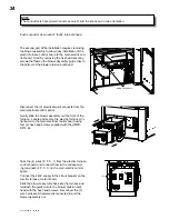
Power and fan/limit wire routing location for right
side return air option. Secure wires to the two loca-
tions as seen in picture.
Power and fan/limit wire routing location for left side
return air option. Secure wires to the right wire tie
location as seen in picture.
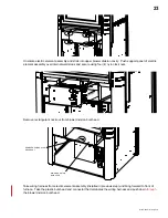
• remove the harness cover from the right side panel (remove three (3) screws). run harness down side
panel of furnace and into 7/8” diameter access hole.
• from the inside of the furnace thread the end of the limit harness through the reducing washer (supplied with
the harness). move the washer up the harness until it reaches the furnace wall, the reducing washer and the
90° elbow of the harness will form a “snap fit” sandwiching the furnace panel between them.
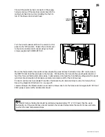
• if wire harness is on right side panel encase with harness cover and replace three (3) mounting screws. if
wire harness is on left side panel replace mounting screws into right side panel and remove equivalent three
(3) screws from left side panel. encase harness with harness cover and fasten using three (3) screws from
left side panel.
• connect the plastic 5 pin pentagonal harness connector to its counter part on the right side of the electric
control panel.
4.5.4 SECurINg wIrE HArNESSES
Содержание HMF100
Страница 9: ...W415 1066 A 03 06 12 9 ...
Страница 43: ...W415 1066 A 03 06 12 43 11 0 service history 43 1 ...
Страница 44: ...W415 1066 A 03 06 12 44 44 1 12 0 notes ...


