


WI850D GEM-P800 Installation Instructions
6
Installation
Mounting the Panel
Mount the Panel close to an unswitched AC
source, a cold-water pipe ground, and a tele-
phone line connection.
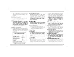
Mounting the Keypad
A keypad should be located near an exit/entry
door. To remove the keypad from the backplate,
insert a small screwdriver into the slots at the
bottom of the keypad. Pull up on the screw-
driver to pop off the cover.
Up to 4 keypads can be connected on individual
wire runs with #22 AWG wire with a maximum
total cable length of 1000 feet. Each keypad
draws approximately 65 mA.
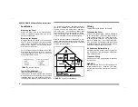
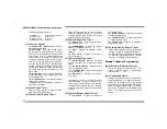
Typical Fire Installation
(Where permitted by local codes)
Install smoke detectors outside each sleeping
area and on each floor, including the basement.
Install the living room and basement smoke de-
tectors near the stairway of the next upper level.
For increased protection, additional detectors
should be installed in areas other than those
required, such as the dining room, bedrooms
and utility room. Heat detectors, rather than
smoke detectors, are recommended in kitchens,
attics, and garages due to conditions that may
result in false alarms and improper operation.
Refer to NFPA Standard 74 (National Fire Pro-
tection Association, Batterymarch Park, Quincy,
MA 02269) for additional information, including
proper mounting methods.
Wiring
Terminal Block Wire Range: 14-22 AWG.
Grounding the Panel
Connect the control-panel EARTH GROUND
screw through a No. 16 AWG or larger wire to a
metal cold-water pipe, a UL Listed ground rod,
or an AC ground connector. Do not use a gas
pipe or a plastic pipe. Use at least #16 AWG
wire. Connect a wire with a ground lug crimped
or soldered onto one end and connect it to the
EARTH GROUND screw in the cabinet.
AC Power and Battery Wiring
Complete all wiring before connecting the bat-
tery or AC Power. Do not plug the transformer
into a switched outlet.
Telephone Wiring
Wire as shown in the wiring diagram in the back
of this manual.
WARNING
The FCC restricts the use of this equipment on
certain telephone lines. Read the FCC state-
ment on the back of this manual to ensure com-
pliance.
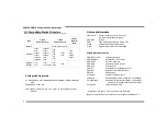
Keypad Wire Color
Control Panel Terminal
RED
12 (+PWR)
BLACK
13 (GND)
GREEN
14 (GREEN)
TABLE
1
K
EYPAD
W
IRING
FIGURE
3
Typical Fire Installation
Содержание GEM-P800
Страница 1: ...WI850E 04 10 NAPCO 2010 GEM P800 Control Panel Communicator Installation Instructions ...
Страница 27: ...27 ...


