


13
cally be unbypassed and any subsequent
violations of the zone will cause an alarm
condition.
[04] 24-Hour Protection
A zone that provides protection at all times,
whether or not the system is armed.
[05] 40 ms Loop Response
Normally loop response is 750 ms, select
this option to change the loop response to
40 ms. The slower the loop response, the
less sensitive the system will be to intermit-
tents (swingers). The programming option
is not permitted for UL installations.
[06] Open Circuit Zones
Program this zone type if unsupervised nor-
mally open circuit devices are required The
programming option is not permitted for UL
installations.
[07] Burg (Steady) Output
Enables the Bell Output on a zone trip for
each zone selected. The Bell Output will
remain ON for the length of time pro-
grammed for
Burg (Steady) Output
[07]
or it
will remain ON until turned off by entering a
valid Arm/Disarm Code; 0 means output will
stay ON until reset.
[08] PGM Output
Enables the PGM Output on a zone trip for
each zone selected. The PGM Output will
remain ON until reset.
[09] Selective Bypass
If programmed, selected zones will be able
to be bypassed by the User. By default, all
zones are permitted to be bypassed.
System Times
[10] Exit Delay
The delay time which permits exit through
an
Exit/Entry Zone
[00] after the system is
armed, allows a user to leave the premises
without setting off an immediate alarm.
Exit
Delay
may be programmed for up to 255
seconds (4¼ minutes); a value of 0 defaults
to 60 seconds.
[11] Entry Delay
Delay time permits entry through
Exit/Entry
Zone(s)
after the system is armed without
setting off an immediate alarm.
Entry Delay
allows the user time to enter and disarm the
system. Upon entering, the keypad sounder
will sound a steady tone (Entry Sound) to
remind the user to disarm the system.
En-
try Delay
Time
[11] may be programmed for
up to 255 seconds (4¼ minutes); a value of
0 defaults to 30 seconds.
Entry Delay
may
be canceled by pressing
F
before or
after arming.
[12] Burg (Steady) Output Time-out
Can be programmed from 1 to 255 min (4¼
hours); 0 means output will stay ON until
turned off by entering an Arm/Disarm Code.
[13] Fire (Pulsed) Output Time-out
Can be programmed from 1 to 255 min (4¼
hours); 0 means output will stay ON until
turned off by entering an Arm/Disarm Code.
[14] Test Timer Interval
Program the interval, in days, between Test
Timer reports. Test Timer Interval may be
programmed from 1 to 255 days.
[15] Line Cut Time-to-Fail
Enable this feature by programming the
delay time required to declare a line cut fail-
ure. Programming 000 will disable line cut
detection.
[16] Wireless Supervisory Timer
A transmitter will send a transmission every
time it is tripped; when there is no activity,
the transmitter sends a supervisory trans-
mission about once an hour. If the receiver
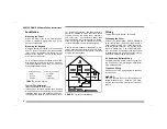
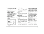
Normally Open Zone Wiring
Wire the normally
open contact
as shown (Zone 4).
EZ Zone Doubling™
resistor is required.
Program the
zone for
Open Circuit
[06] operation.
3.
9K
(Z)
ZONE 1
(E)
2.
2K
ZONE 4
FIGURE
6
O
PEN
C
IRCUIT
W
IRING
Содержание GEM-P800
Страница 1: ...WI850E 04 10 NAPCO 2010 GEM P800 Control Panel Communicator Installation Instructions ...
Страница 27: ...27 ...


