© 2001, Myricom, Inc.
-- 14 --
Revision: 27 August 2001
4. Port Line Cards
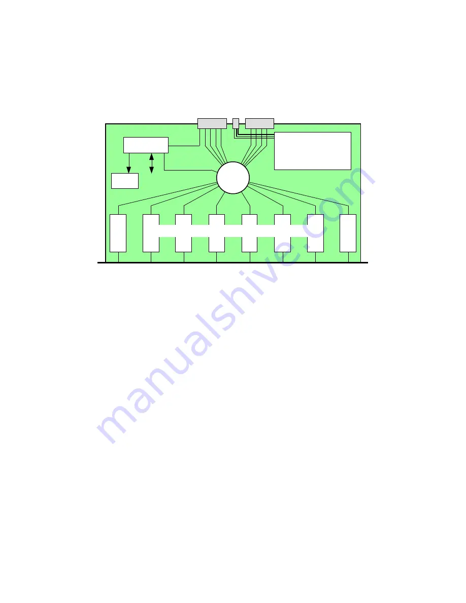
The following block diagram illustrates the structure of any of the port line cards that include an
XBar16. This block diagram also approximates the physical layout of these circuit boards.
µC
Clocks
Backplane Interface
XBar16
8
9
10
11
12
13
14
15
Front-panel Ports
Serial link
Scan path
Sense &
Control
Power & hot-swap
circuits
Physical-Level Conversion Circuits
dual +12V
0
1
2
3
4
5
6
7
The backplane interface includes 8 SAN-2000 links numbered 0...7, as shown, corresponding to
the port numbering of the XBar16. The backplane interface also includes dual +12V power, and
a serial-link interface to the monitoring line card. The front-panel ports may be:
•
8 Fiber ports (M3-SW16-8F line card),
•
8 Serial ports (M3-SW16-8S line card),
•
8 SAN ports (M3-SW16-8M and M3-SW16-4DM line cards), or
•
4 legacy LAN ports (M3-SW12-4L line card),
depending upon the Physical-level conversion circuits. The port numbers, 8...15 (8...11 for the
M3-SW12-4L line card), appear on the front panel silkscreen, and correspond to the port
numbering of the XBar16.
Inasmuch as the native Physical level (PHY) of the XBar16 ports is SAN, there are no
conversion circuits for the M3-SW16-8M or the M3-SW16-4DM. The only difference between
these two line cards is that for the M3-SW16-8M, the 8 front-panel ports appear on the A link of
8 SAN connectors, with the B link unused; whereas for the M3-SW16-4DM, the 8 front-panel
ports appear on the A&B links of 4 SAN connectors.
The speed of the front-panel SAN ports of the M3-SW16-8M and M3-SW16-4DM line cards can
be set individually to SAN-2000 or to SAN-1280. Both line cards include a set of mechanical
switches for setting the default data rate, and for setting the default state of the high-availability
(HA) features to ‘on’ or ‘off.’ The line card must be ejected from an enclosure slot to change the


