© 2001, Myricom, Inc.
-- 9 --
Revision: 27 August 2001
Guide to Myrinet-2000 Switches and Switch Networks
Principles of Operation
1. Introduction
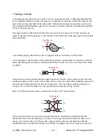
The basic building block of this family of switch products is a 16-port Myrinet crossbar switch,
which is implemented on a single chip designated as the XBar16. The XBar16 is pictured in the
block diagrams below as a circle, and the Myrinet links as lines. A
Myrinet link
is a full-duplex
pair of Myrinet channels.
The structure of these highly modular switches is best understood by starting with the maximal
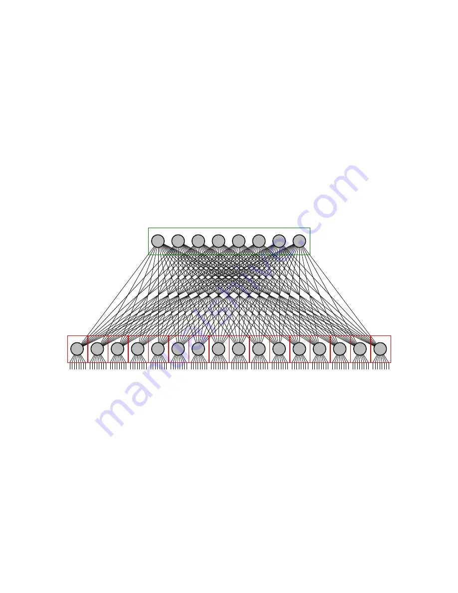
configuration within a single enclosure, a 128-host Clos network, which includes 24 XBar16s:
Spine of the Clos Network (backplane)
8
hosts
8
hosts
8
hosts
8
hosts
8
hosts
8
hosts
8
hosts
8
hosts
8
hosts
8
hosts
8
hosts
8
hosts
8
hosts
8
hosts
8
hosts
8
hosts
Clos
“spreader”
network
Ports to up to 128 hosts (line cards)
The network pictured above provides routes from any host to any other host.
•
There is a unique shortest route between hosts connected to the same XBar16.
•
The eight minimal routes between hosts connected to different XBar16s traverse three
XBar16 switches.
This topology provides so many paths between hosts that the
minimum bisection
of this network
– its traffic-handling capacity – is as large as possible. This
full-bisection
and other properties of
the Clos network topology will be discussed in greater detail starting in section 7.
The upper row of 8 XBar16s is the Clos network
spine
, which is packaged as an active backplane
(green box) built into an enclosure that also provides power and cooling. The spine is connected


