


© 2001, Myricom, Inc.
-- 12 --
Revision: 27 August 2001
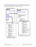
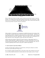
The M3-E16 enclosure, which has 2 port-line-card slots, is a special case. The direct
extrapolation of the networks above would employ one XBar16 on the spine, but it is not needed.
Instead, the backplane of the M3-E16 enclosure simply connects like ports of the two line cards:
8
hosts
8
hosts
8 links
8
hosts
8
hosts
8 links
Spine line card
With regular port line cards with switches, even the form on the left has an unnecessary level of
switching. However, the Fiber and Serial versions of the Myrinet-2000 switch line cards are
available in an alternative “spine” version that connects the 8 front panel ports through Physical-
level conversion circuitry directly to the backplane spine, as illustrated on the right. As we shall
see later, the spine line cards have other applications.
3. Other Features of the Enclosures and Line Cards
The Myrinet-2000 enclosures and line cards are designed so that the line cards or the fan tray can
be “hot-swapped,”
i.e.,
inserted or removed from an enclosure that is powered. See the hot-swap
instructions starting on page 5. There is, in fact, no power switch on the enclosure, lest a switch
network accidentally be powered off.
Other features of the enclosure products include:
•
a slot for an optional line card for monitoring and control of the switch. This monitoring
line card (product code M3-M) is the same size as the port line cards, but has different
backplane connectors, such that it can be inserted only into the top line-card slot. The
M3-M includes a “big” microcontroller that communicates externally via either of two
Ethernet ports, and internally via serial communication links. These serial
communication links connect through the backplane with a “small” microcontroller (µC)
on each line card, with a µC associated with each XBar16 on the backplane, and with a
µC that monitors the rotation rate of the fans. The switch network operates without
intervention of the monitoring line card, so that the monitoring line card is optional and
hot-swappable.
•
either a single, built-in power supply, or dual-redundant hot-pluggable power supplies
2
.
These power supplies p12V from an IEC input of 100-127V~ or 200-240V~,
either 50Hz or 60Hz. Dual +12V power-distribution networks convey the +12V power to
the backplane, to each line card, and to the fan tray. At each of these locations, the two
sources of +12V are combined with diodes, and the voltages required by the circuitry on
the line cards and backplanes (typ3.3V, +2.5V, and/or +1.25V) are generated
2
Expected to be available for the M3-E128 in 4Q01.


