background image

Oracle Talari E1000 Installation Guide 

Purpose 

This guide will help you set up your E1000 using typical 
deployment scenarios. 

E1000 Overview 


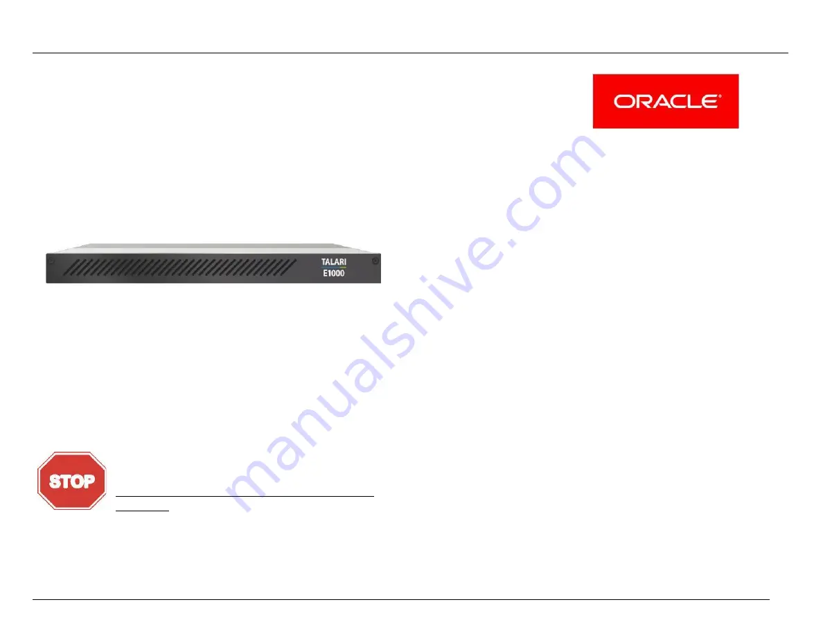
The E1000 is an extension of the E-series of Oracle Talari 
Appliances and intended for use in large branch or regional 
offices that require higher performance and port density than the 
E100 provides. The E1000 supports all major Talari Adaptive 
Private Network (APN) features, including Service Chaining, and 
WAN Optimization. 

IMPORTANT : 


Quick Reference 

E1000 Hardware Options ........................................................    2 
What’s Included .......................................................................    4 
E1000 Front Panel ...................................................................    5 
E1000 Back Panel ...................................................................    5 

E1000: No Expansion Card ..................................................    5 
E1000: 10G Fiber (2 Port) Expansion Card ..........................    6 
E1000: Fail to Wire Copper (4 Port) Expansion Card ...........    7 

Unpacking and Inspection Checklist ........................................    8 
Rack Mounting  ........................................................................    8 

4-Post Rack Mounting (Recommended) ...............................    8 
2-Post Rack Mounting .........................................................    12 

Network Deployment Options.................................................    14 

E1000 as a Router (Gateway, Fail to Block) ........................    14 
E1000 as Layer 2 Fail-To-Wire (Overlay) ............................    14 
E1000 with MPLS & Internet Hybrid  ...................................    14 

Installation Options .................................................................    15 

Easy 1st Install .....................................................................    15 
Manual Install .......................................................................    19 


Your E1000 ships with a piece of foam behind the 
faceplate to prevent damage during shipping. The 
foam must be removed before powering on the  
appliance to avoid overheating the device. 
(Please refer to the Unpacking and Inspection 
Checklist for instructions.) 


Version 1.1 

Содержание Talari E1000

Страница 1: ... Front Panel 5 E1000 Back Panel 5 E1000 No Expansion Card 5 E1000 10G Fiber 2 Port Expansion Card 6 E1000 Fail to Wire Copper 4 Port Expansion Card 7 Unpacking and Inspection Checklist 8 Rack Mounting 8 4 Post Rack Mounting Recommended 8 2 Post Rack Mounting 12 Network Deployment Options 14 E1000 as a Router Gateway Fail to Block 14 E1000 as Layer 2 Fail To Wire Overlay 14 E1000 with MPLS Internet...

Страница 2: ...re Option Each E1000 hardware option can be visually identified by comparing the back of the appliance to the E1000 Back Panel images on pages 4 6 of this guide If the E1000 is still in the original shipping box the hardware option can also be identified by the last line of text on the external shipping label Related Publications The following documents are available Talari APN 7 0 New Features Gu...

Страница 3: ...No other rights are granted to the U S Government This software or hardware is developed for general use in a variety of information management applications It is not developed or intended for use in any inherently dangerous applications including applications that may create a risk of personal injury If you use this software or hardware in dangerous applications then you shall be responsible to t...

Страница 4: ...ion is defined as a problem with the installed equipment that severely affects service traffic or maintenance capabilities and requires immediate corrective action Critical situations affect service and or system operation resulting in one or several of these situations A total system failure that results in loss of all transaction processing capability Significant reduction in system capacity or ...

Страница 5: ...Post Racks 2x Non Threaded Brackets for 2 Post Racks 2x Front Outer Rails 2x Back Outer Rails 4 What s Included 1x Blue Management Cable 2x Green LAN Cables 1x Red Crossover Cable 2x Orange WAN Cables 2x Inner Expansion Rails Optional Rack Mounting Hardware Version 1 1 ...

Страница 6: ...Where necessary separate sub sections for each hardware option are provided within this guide E1000 No Expansion Card Power A C Power Connector Fan Fan exhaust Port 1 Gigabit Ethernet Bypass pair with Port 2 Port 2 Gigabit Ethernet Bypass pair with Port 1 Port 3 Gigabit Ethernet Bypass pair with Port 4 Port 4 Gigabit Ethernet Bypass pair with Port 3 Console DB9 console port 115200 8 N 1 USB ports ...

Страница 7: ...When ordering or using existing SFP modules with this appliance the following SFP modules are supported in conjunction with the E1000 10G Fiber 2 Port expansion card Description Intel Part Intel Short Range Dual Rate 10GBASE SR 1000BASE SX Supplier Part FTLX8571D3BCVIT1 or AFBR 709DMZ IN2 E10GSFPSR Intel Long Range Dual Rate 10GBASE LR 1000BASE LX Supplier Part FTLX1471D3BCVI31 E10GSFPLR Intel Eth...

Страница 8: ...wn directly above is identical to the E1000 No Expansion Card appliance shown on page 4 with the addition of the following Port 9 Gigabit Ethernet Bypass pair with Port 10 Port 10 Gigabit Ethernet Bypass pair with Port 9 Port 11 Gigabit Ethernet Bypass pair with Port 12 Port 12 Gigabit Ethernet Bypass pair with Port 11 Version 1 1 ...

Страница 9: ... device based upon selected rack type Safety Recommendations Prior to installing the device in a rack adhere to the following rack installation guidelines Ensure that there is adequate airflow in the rack Restricted airflow can damage the equipment Leave at least 1U of vertical space between each device installed in the rack The rack width and depth should allow for proper serviceability and cable...

Страница 10: ...ect direction Note For both front and back rails for the E1000 it is important to ensure that they are pointing in the correct orientation Front or Back even if the arrows or the text are displayed upside down 2 Place one of the Back Outer Rails on top of one of the Front Outer Rails and align the pegs circled in Figures 1 and 2 below in blue with the matching holes circled in green Figure 1 Pegs ...

Страница 11: ...portant safety information about removing an appliance with Inner Expansion Rails installed Installation 1 Mount the assembled outer rails to the rack by using the self locking arm locks on each end circled in Figures 3 and 4 below in blue Make sure the Front arrow is pointing towards the front of the rack and the Back arrow is pointing to the back of the rack The rails will click into place Caref...

Страница 12: ...e Figures 3 and 4 circled in blue Note When removing an appliance with Inner Expansion Rails installed please note that each Inner Expansion Rail has an additional Side Rail Lock which must be depressed before the appliance can be removed from the rack If a person attempts to remove an appliance with Inner Expansion Rails from a rack without assistance there is an increased risk of dropping and da...

Страница 13: ...Assembly 5 Attach 1 selected mounting bracket to the raised oblong middle section of one of the Front Outer Rails with a short rounded screw contained in rack mounting hardware bag Ensure that the Front arrow on the bracket points towards the front of the rail a Note The word Limit on the Front Outer Rail should still be visible once the bracket is joined to the Front Outer Rail 6 Repeat with seco...

Страница 14: ...you hear the click from the Side Rail Locks on the E1000 indicating proper installation Removal 9 Pull side of device towards the front of the rack until the E1000 Side Rail Locks are exposed 10 Depress the Side Rail Locks on both sides of the E1000 simultaneously and then continue to pull device forward until released from rails Figure 6 Side View of E1000 Showing Side Rail Locks Version 1 1 ...

Страница 15: ...0 is deployed on the LAN side of the gateway and bypass pairs are configured as Fail To Wire Use this design if you prefer to retain existing edge devices or plan to install an alternative edge device on the WAN side of the Talari Appliance Proceed to the pages below based on your installation method Easy 1st Install Page 14 Manual Install Page 18 E1000 with MPLS Internet Hybrid Description The E1...

Страница 16: ...e is applied and the appliance will need to be factory defaulted before Easy 1st Install can be attempted again Valid ports for each hardware option are highlighted in green below while invalid ports are indicated with a red symbol Port 1 Gigabit Ethernet Bypass pair with Port 2 Port 2 Gigabit Ethernet Bypass pair with Port 1 Port 3 Gigabit Ethernet Bypass pair with Port 4 Port 4 Gigabit Ethernet ...

Страница 17: ... Ports 9 and 10 should only be configured with Bypass Mode set as Fail to Block on an E1000 with 10G Fiber expansion card The 10G Fiber expansion card does not support Fail to Wire and the Talari service will not start if a configuration specifying Fail to Wire for these ports is applied to an E1000 with 10G expansion card Version 1 1 ...

Страница 18: ...he NCN please see the instructions for manual installation Active Appliance Package The NCN must be running an active configuration which includes the E1000 for the site being installed Client Site Connectivity Internet DHCP and DNS connectivity to the management interface are required to use Easy 1st Install If one or more are not available please see the instructions for manual installation If t...

Страница 19: ...omplete proceed to the next section Deploy the Talari Appliance 17 Ensure that the appliance management interface is cabled for Internet connectivity 18 Connect the power cord to the E1000 Connect the other end to an appropriately grounded power source The E1000 will power on automatically 19 The E1000 will begin the Easy 1st Install process Please allow up to ten minutes for the process to comple...

Страница 20: ...ploaded via Local Change Management as outlined in steps 4 7 of Deploying the Talari Appliance to bring up the Talari service Valid ports for each hardware option are highlighted in green below while invalid ports are indicated with a red symbol Port 1 Gigabit Ethernet Bypass pair with Port 2 Port 2 Gigabit Ethernet Bypass pair with Port 1 Port 3 Gigabit Ethernet Bypass pair with Port 4 Port 4 Gig...

Страница 21: ...et non bypass Note Ports 9 and 10 should only be configured with Bypass Mode set as Fail to Block The 10G Fiber expansion card does not support Fail to Wire and the Talari service will not start if a configuration specifying Fail to Wire for these ports is applied to an E1000 with 10G expansion card Version 1 1 2 0 ...

Страница 22: ...ents The network administrator must have an active configuration which includes a client package for this site running on the NCN An appropriate IP address subnet mask and gateway for the management interface should be provided for the on site user to configure If the network administrator will have access to the new appliance once an on site user configures the management interface proceed to ste...

Страница 23: ... Address for the Talari as provided by your network administrator f Click Change Settings If your network administrator will be applying the configuration package you may now restore the original network settings on your PC 4 To apply the configuration package navigate to Manage Appliance Local Change Management 5 Click Browse and select the zip package provided by your network administrator then ...

Страница 24: ...Version 1 1 2 3 ...

Отзывы: