


30
Installation
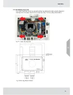
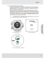
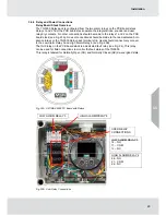
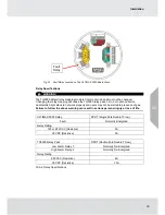
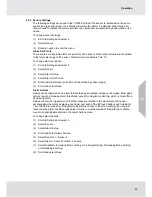
Fig. 24 Fault Relay Located on The ULTIMA X5000 Board Stack
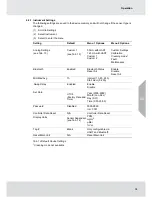
Relay Specifications
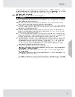
WARNING!
The TG5000 default relay mapping mode is Common mode and must not be changed.
Changing the relay mapping will cause the TG5000 relay pack, horn, horn silence button
and installed light stack to not work properly and users may not be alerted to presence of gas.
Failure to follow the above warning can result in serious personal injury or loss of life.
ULTIMA X5000 Relay
SPDT (Single Pole Double Throw)
Fault
Normally Energized
Relay Rating
125 or 250 VAC (Resistive)
5A
30 VDC (Resistive)
5A
TG5000 Relay Pack
DPDT (Double Pole Double Throw)
Low Alarm, Relay 3
Normally De-Energized
High Alarm, Relay 4
Normally De-Energized
Relay Rating
250 VAC (Resistive)
6A
30 VDC (Resistive)
1.5A
Tab. 8 Relay Specifications
US
US
Fault
Relay
Содержание TG5000
Страница 1: ...Operating Manual TG5000 Gas Monitor Order No 10212126 L Y REV 0 US ...
Страница 36: ...36 Operation US ...
Страница 46: ...46 Operation US ...
Страница 62: ...62 Maintenance US ...
Страница 63: ...63 Maintenance US ...
Страница 64: ...64 Maintenance US ...
Страница 65: ...65 Ordering Information Tab 17 Troubleshooting 1 Lower numbers have higher priority US Maintenance ...
Страница 70: ...70 Appendix Calibration Guide and Additional Gases US ...
Страница 71: ...71 Appendix Calibration Guide and Additional Gases R 32 US ...
Страница 72: ...72 Appendix Calibration Guide and Additional Gases US ...
Страница 73: ...73 Appendix Calibration Guide and Additional Gases Tab 21 XIR PLUS Calibration Guide for Additional Gases US ...
Страница 75: ...For local MSA contacts please visit us at MSAsafety com ...


