PAGE 22 — DCA300SSJU4F2 60 HZ GENERATOR • OPERATION MANUAL — REV. #0 (06/26/18)
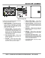
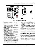
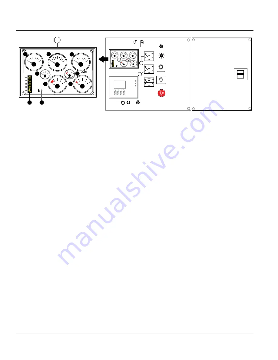
The definitions below describe the readouts and functions
of the Gauge Unit Assembly (Figure 10).
1.
Gauge Unit Assembly
— This assembly houses the
various engine monitoring gauges. These gauges
indicate: oil pressure, water temperature, charging
voltmeter, generator load, fuel level, DEF level and
engine speed RPM (tachometer).
A.
Oil Pressure Gauge
— During normal operation,
this gauge should read approximately 44 psi.
(300 kPa). When starting the generator, the oil
pressure may read a little higher but after the
engine warms up, the oil pressure should return
to the correct pressure range.
B.
Water Temperature Gauge
— During normal
operation this gauge should read between 185°
and 207°F (85°~97°C).
C.
Tachometer
— Indicates engine speed in RPM’s
for 60 Hz operation. This meter should indicate
1800 RPM’s when the rated load is applied.
D.
Battery Voltmeter Gauge
— During normal
operation this gauge indicates a minimum 14 VDC.
E.
Generator Load Gauge
— Indicates the generator
load rate. It is recommended the load be above the
red area (20%) for maintaining sufficient exhaust
temperature.
F.
Fuel Gauge
— Indicates amount of diesel fuel
available. The red area in the gauge indicates a
low fuel level (20%).
G.
DEF Gauge
— Indicates amount of diesel exhaust
fluid available. The red area in the gauge indicates
a low DEF level (10%).
H.
Exhaust System State Indicator Lamps
— Lamps
illuminate when engine is at Exhaust System State or
DEF state. Refer to the maintenance section of this
manual for more detailed indormation.
I.
Low fuel Warning LED
— When ON (lit) indicates
that fuel level is low.
Figure 10. Gauge Unit
Series 800 Controller
ECU
Engine Started
Shutdown
Pre-Alarm
Alarm
Acknowledge
Screen
Change
Program
Exit
Option
OFF
U-V
W-U
V-W
OFF
V
W
U
INCREASE
DECREASE
4
5
PSI
OIL PRESS
0
25
50
75
100
°F
WATER TEMP
100
140
180
220
260
°F
FUEL
E
½
F
RPMX10
SPEED
0
120
150
180
210
60
E
1
°F
DEF
E
½
F
ECU
Integrated Gauge Panel
VOLTS
0
12
18
24
30
%
0
50
100
D
A
B
C
G
F
Check
DEF
Emissions
Failure
Emissions
Failure
Regen
Needed
Regen
Inhibit
Low
Fuel
PSI
OIL PRESS
0
25
50
75
100
°F
WATER TEMP
100
140
180
220
260
°F
FUEL
E
½
F
RPMX10
SPEED
0
120
150
180
210
60
°F
DEF
E
½
F
ECU
Integrated Gauge Panel
VOLTS
0
12
18
24
30
%
0
50
100
Check
DEF
Emissions
Failure
Emissions
Failure
Regen
Needed
Regen
Inhibit
Low
Fuel
I
H
GAUGE UNIT ASSEMBLY
Содержание WHISPERWATT DCA300SSJU4F2
Страница 13: ...DCA300SSJU4F2 60 HZ GENERATOR OPERATION MANUAL REV 0 06 26 18 PAGE 13 NOTES ...
Страница 62: ...PAGE 62 DCA300SSJU4F2 60 HZ GENERATOR OPERATION MANUAL REV 0 06 26 18 ENGINE WIRING DIAGRAM ECU 845 ...
Страница 73: ...DCA300SSJU4F2 60 HZ GENERATOR OPERATION MANUAL REV 0 06 26 18 PAGE 73 NOTES ...

