background image

- 6 - 


ATTENTION 

Use the antennas correctly: Use 2.4GHz antennas if the 
AWK-6232-M12 operates in IEEE 802.11b/g/n. Use the 5GHz 
antennas for operations in IEEE802.11a/n. Make sure your 
antenna installation is within a safe area covered by a lightning 
protection or surge arrest system. 


Wall Mounting 

In most applications, wall mount provides an easier installation. You will 
find it quite easy to mount AWK-6232-M12 on the wall, as illustrated 
below. 


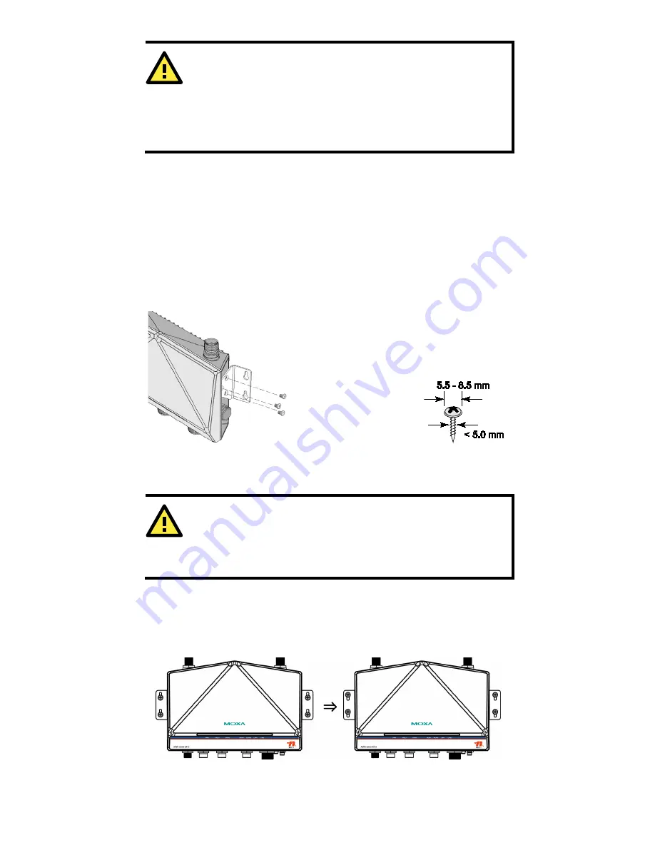
STEP 1: 

Attach the wall-mounting kit 
with M4 screws, as shown in 
the diagram below. 


STEP 2:


Mounting the AWK-6232-M12 on the 
wall requires 4 screws. Use the 
AWK-6232-M12 device, with 
wall-mounting kit attached, as a guide 
to mark the correct locations of the 4 
screws. The heads of the screws are 
recommended to be between 5.5mm 
and 8.5 mm in diameter, and the shafts 
should not be more 
than 5.0 mm in 
diameter, as shown 
in the figure. 
 

Do not screw the screws all the way in to the wall—leave a space of about 
2 mm to allow room for sliding the wall-mounting kit between the wall and 
the screws. 


ATTENTION 

You can test the screw head and shank size by inserting the screw 
into one of the keyhole shaped apertures of the wall mounting 
plates before it is screwed into the wall. 


STEP 3: 

Once the screws are fixed into the wall, insert the four screw heads 
through the large opening of the keyhole-shaped apertures, and then 
slide the AWK-6232-M12 downwards, as indicated to the right. Tighten 
the four screws for added stability. 


Содержание AWK-6232-M12

Страница 1: ... 2012 Moxa Inc All rights reserved Reproduction without permission is prohibited P N 1802062320011 AWK 6232 M12 Hardware Installation Guide Moxa AirWorks Second Edition March 2012 ...

Страница 2: ... 6232 M12 wireless AP bridge client 4 Dual band omnidirectional antennas 5 2 dBi N type male 2 4 5 GHz Wall mounting kit includes 2 supports Field installable power plug Field installable M12 8 pin male LAN plug 2 transparent plastic sticks for field installable plugs 1 metal cap to cover M12 female LAN connector 1 metal cap to cover RJ45 connector 1 metal cap to cover M12 male DI O connector Docu...

Страница 3: ...to 85 C SFP 1GZXLC Small form factor pluggable transceiver with 1000BaseZX LC 80 km 0 to 60 C SFP 1GZXLC T Small form factor pluggable transceiver with 1000BaseZX LC 80 km 40 to 85 C SFP 1GEZXLC Small form factor pluggable transceiver with 1000BaseEZX LC 110 km 0 to 60 C SFP 1GEZXLC 120 Small form factor pluggable transceiver with 1000BaseEZX LC 120 km 0 to 60 C NOTE The above items come with the ...

Страница 4: ...fective you must save the change and then click Restart Save and Restart button to apply all changes Panel Layout of the AWK 6232 M12 1 RF 1 s 1A and 1B antennas 2 RF 2 s 2A and 2B antennas 3 LEDs for PWR FAULT STATE WLAN1 WLAN2 LAN1 and LAN2 4 M12 A coding connector for PWR1 and PWR2 5 M12 8 pin connector for DI DO 6 10 100 1000BaseT X M12 Port LAN1 and LAN2 7 RS 232 console port 8 Reset button 9...

Страница 5: ...imensions unit mm Attaching Antennas The AWK 6232 M12 inclues two dual band omnidirectional antenna by default Attach the antennas as illustrated below Step 1 Use your fingers and hold the antenna metal N type connector Step 2 Screw the antenna N type connector male onto the AWK 6232 M12 device s N type connector female Caution Do not hold the rubber plate to screw the antenna on to the AWK 6232 M...

Страница 6: ...unting kit attached as a guide to mark the correct locations of the 4 screws The heads of the screws are recommended to be between 5 5mm and 8 5 mm in diameter and the shafts should not be more than 5 0 mm in diameter as shown in the figure Do not screw the screws all the way in to the wall leave a space of about 2 mm to allow room for sliding the wall mounting kit between the wall and the screws ...

Страница 7: ...mounting To install the DIN Rail mounting kits tightly attach the two DIN Rail mounting kits on the rear panel of AWK 6232 M12 with 12 screws 6 screws for each kit To Install STEP 1 Use the recessed button on the spring loaded bracket to lock it into position STEP 2 Insert the top of the DIN Rail into the slot just below the upper hook of the DIN Rail mounting kit Push the AWK 6232 M12 toward the ...

Страница 8: ...should be routed separately You can use the type of signal transmitted through a wire to determine which wires should be kept separate The rule of thumb is that wiring with similar electrical characteristics can be bundled together Keep input wiring and output wiring separate It is strongly advised that you label wiring to all devices in the system when necessary Grounding Moxa AWK 6232 M12 Ground...

Страница 9: ...ce voltage is stable ATTENTION Do not use the PoE Injector Instead please use an IEEE802 3af or IEEE802 3at compliant PSE Power Sourcing Equipment for PoE Power over Ethernet Plus devices Wiring the Digital Inputs and Relay Contact Digital Output The AWK 6232 M12 has two sets of digital input DI1 and DI2 Each DI comprises two contacts of the 8 pin M12 connector on the AWK 6232 M12 s bottom panel T...

Страница 10: ...M12 has 10 100 1000BaseT X Ethernet ports 8 pin shielded M12 connector with A coding The 10 100 1000BaseT X ports located on the AWK 6232 M12 s bottom panel are used to connect to Ethernet enabled devices Below we show pinouts for both MDI NIC type ports and MDI X HUB Switch type ports Pinouts for the 10 100 1000BaseT X M12 8 pin Port Pin Signal 1 Relay 2 3 DI1 I1 4 DI1 COM_1 5 DI2 I2 6 DI2 COM_2 ...

Страница 11: ...ignment and solder wires with 2 Then assemble and in order 3 Test the plug to ensure the quality RS 232 Connection The AWK 6232 M12 has one RS 232 8 pin RJ45 console port located on the bottom panel Use either an RJ45 to DB9 or RJ45 to DB25 cable to connect the Moxa AWK 6232 M12 s console port to your PC s COM port You may then use a console terminal program to access the AWK 6232 M12 for console ...

Страница 12: ...2 contains several LED indicators The function of each LED is described in the table below LED Color State Description PWR Green On Power is being supplied from power input 1 or 2 or PoE Off Power is not being supplied FAULT Red Blinking slow Cannot get an IP address from the DHCP server interval 1 sec Blinking fast IP address conflict interval 0 5 sec Off Error condition does not exist STATE Gree...

Страница 13: ... 1Q VLAN Spread Spectrum and Modulation typical DSSS with DBPSK DQPSK CCK OFDM with BPSK QPSK 16QAM 64QAM 802 11b CCK 11 5 5 Mbps DQPSK 2 Mbps DBPSK 11 Mbps 802 11a g 64QAM 54 48 Mbps 16QAM 36 24 Mbps QPSK 18 12 Mbps BPSK 9 6 Mbps 802 11n 64QAM 300 Mbps to BPSK 6 5 Mbps multiple rates supported Operating Channels central frequency US 2 412 to 2 462 GHz 11 channels 5 18 to 5 24 GHz 4 channels EU 2 ...

Страница 14: ...6 Mbps 86 dBm 9 Mbps 85 dBm 12 Mbps 82 dBm 18 Mbps 80 dBm 24 Mbps 76 dBm 36 Mbps 72 dBm 48 Mbps 70 dBm 54 Mbps RX Sensitivity MIMO 802 11a n 68 dBm MCS15 40 MHz 70 dBm MCS7 40 MHz 69 dBm MCS15 20 MHz 71 dBm MCS7 20 MHz 802 11g n 69 dBm MCS15 20 MHz 71 dBm MCS7 20 MHz Protocol Support General Protocols DNS HTTP HTTPS IP ICMP SNTP TCP UDP RADIUS SNMP PPPoE DHCP AP only Protocols ARP BOOTP DHCP STP R...

Страница 15: ...rds and Certifications Safety UL 60950 1 EN 60950 1 EMC EN 301 489 1 17 FCC Part 15 Subpart B EN 55022 55024 Radio EN 300 328 EN 301 893 DSPR Japan Rail Traffic EN 50155 EN 50121 1 4 Note Please check Moxa s website for the most recent certification status Warranty Warranty Period 5 years Details See www moxa com warranty RESTRICTED ACCESS ONLY This equipment is intended to be installed only in re...

Страница 16: ...icas Toll free 1 888 669 2872 Tel 1 714 528 6777 Fax 1 714 528 6778 Moxa China Shanghai office Toll free 800 820 5036 Tel 86 21 5258 9955 Fax 86 21 5258 5505 Moxa Europe Tel 49 89 3 70 03 99 0 Fax 49 89 3 70 03 99 99 Moxa Asia Pacific Tel 886 2 8919 1230 Fax 886 2 8919 1231 ...

Отзывы: