SD34002g_e.doc / Sep-13
Page 28 / 60
F02
Range
Default
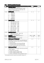
F02.013
Display Update Time:
0 = immediate display update after each result (fastest)
100 = timed update, approx. 1/sec (slowest)
0 - 100
0
F02.014
Sampling Pulses: *
a)
Number of input impulses on channel A to calculate a
measuring result
With all settings >0 the function of the parameters
"Sampling Time" (F03.024 and F04.036) is disabled
0 – 30 000
0.50
F02.015
Wait Time Sampling:
Time limit: if with use of parameter F02.014 the input pulses
should get interrupted, a result will be calculated and displayed
latest after elapse of this time limit
0.01 - 99.99 sec
0
F02.016
Synchronization:
*b)
Synchronization of encoder1 / encoder2 measurement
0, 1
0
0 =
Synchronization OFF. Evaluation of encoder1/encoder2
happens fully independently and at different times
1 =
Synchronization ON. Evaluation of encoder1/encoder2
is synchronized and happens at the same time
F02.017
Input Limitation:
*c)
Limitation of the input frequency (digital low-pass filter)
0 - 3
0
0 =
no limitation of the input frequency
1 =
Limitation to 500 kHz max.(both encoder inputs)
2 =
Limitation to 100 kHz max.(both encoder inputs)
3 =
Limitation to 10 kHz max.(both encoder inputs)
F02.018
Percent Format: Decimal presentation of percentaged display
0 - 3
0
0 = /-999999 %
1 = /-99999,9 %
2 = /-9999,99 %
3 = /-999,999%
*) Important Hints:
a. With irregular and out-of-round motion-sequence it may be advantageous to use a
fixed number of input pulses for sampling, instead of a sampling time. This method
is suitable to stabilize or suppress undulation of the display (e.g. with unbalanced
and eccentric movements) because an overall average of one undulation is formed
b. It is advisable to always use the synchronized mode whenever measuring speed
ratios or percentaged speed difference. Otherwise unacceptable variation of the
display may occur, caused by the different timing of the two speed values
With the synchronization set to ON, parameters "Sampling Time1" (or "Sampling
Pulses") as well as "Wait Time1" are used conjointly for both encoders and the
corresponding settings for encoder 2 are inoperative. The response time of the unit
depends in each case on the lower one of the two input frequencies
c. Where the low-pass filter is used to limit the input frequency, higher frequencies
than indicated will no more be evaluated correctly


