SD34002g_e.doc / Sep-13
Page 7 / 60
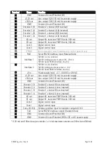
3. Electrical Connections
17 18 19 20 21
23 24 25 26 27 28 29 30 31 32
1 2 3 4 5 6 7 8 9 10 11 12 13 14 15 16
GN
D
GN
D
GN
D
GN
D
GN
D
+V
in
+5
,2
V
au
x.
ou
t
+5
,2
V
au
x.
ou
t
+2
4V
au
x.
ou
t
+2
4V
au
x.
ou
t
En
co
de
r2
B
En
co
de
r2
A
En
co
de
r1
B
En
co
de
r1
A
En
co
de
r1
/A
En
co
de
r1
/B
En
co
de
r2
/A
En
co
de
r2
/B
K2
ou
t
K1
ou
t
K3
ou
t
K4
ou
t
Co
nt
.1
Co
nt
.2
Co
nt
.4
Co
nt
.3
Co
m
+
(K
1-
K4
)
Tx
D
(R
S2
32
)
In
te
rfa
ce
2
*)
In
te
rfa
ce
1
*)
Rx
D
(R
S2
32
)
PR
OG
X1
X2
+5
-
A
/A
B
/B
+5
-
A
/A
B
/B
Encoder1*
Encoder 2*
Cont1
Cont2
Cont3
Cont4
Digital
Control
Inputs
RxD
TxD
GND
RS232
-
+
24 V DC
Power supply
Com+ (K1 - K4)
K1 out
K2 out
K3 out
K4 out
Fast
transistor
outputs
+24
+24
0V, GND
PROG
18
24
23
20
19
22
21
11
12
6
5
27
28
30
3
31
17 1
4
29
26
25
7
8
32
2
16
Interface 2 *)
15
14
13
10
9
24 V AC
*) Example shows wiring
for encoders with 5 volts
power supply and RS422
line driver output
Interface 1 *)
Series "SD"
Series "SA"
Series "SR"
*) Interface 1:
- n.c. -
Analogue output 0/4 - 20 mA
RS 485, B (-)
*) Interface 2:
- n.c. -
Analogue /- 10 V
RS 485, A (+)


