MC70001c_de.doc / Nov-15
Page
3
/
14
2. Stromversorgung
Das Gerät wird über die mit „DC IN“ bezeich-
neten Klemmen mit einer unstabilisierten
Gleichspannung von 18
– 35 VDC versorgt.
Die Stromaufnahme hängt u.a. von der Höhe der
Versorgungsspannung und der Belastung der
+5V
– Hilfsspannung ab. Bei 24 VDC ergibt sich
ein Gerätestrom von ca. 300 mA zuzüglich 25%
des auf der Hilfsspannungsseite entnommenen
Geberstromes.
Sofern der Minuspol der Geräteversorgung nicht
ohnehin geerdet ist, wird eine Erdung in
unmittelbarer Nähe des Gerätes empfohlen. Der
am Gerät befindliche Erdungsanschluss ist mit
dem Metallgehäuse des Gerätes, aber nicht mit
der internen GND verbunden.
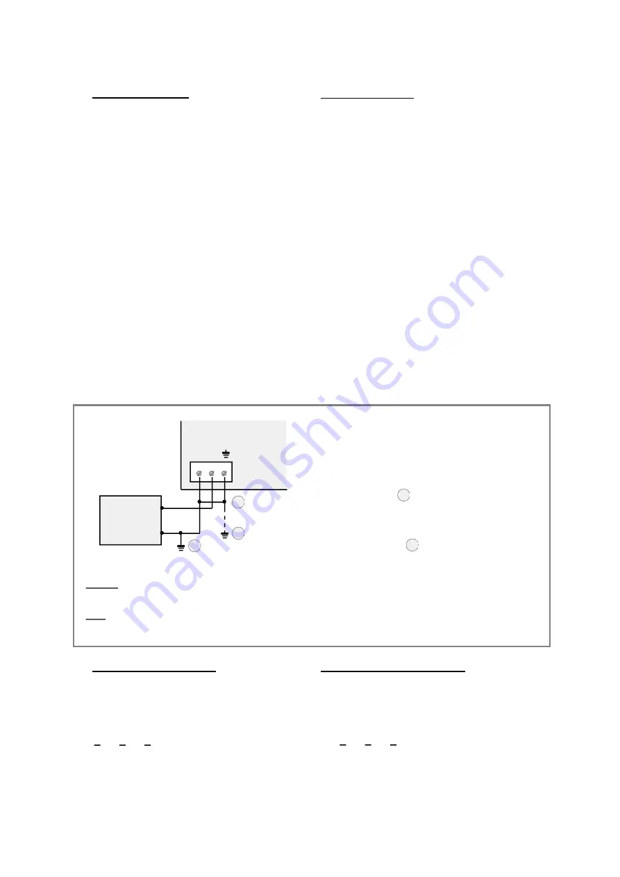
Die folgende Anschlussweise hat sich auch
unter extremen EMV-Bedingungen bestens
bewährt. Alle später ausgeführten Abschirm-
Vorschriften basieren auf der hier gezeigten
Anschlussweise der Stromversorgung. Ab-
weichende Verdrahtungweisen mögen ebenso
problemlos funktionieren, eine Gewähr hierfür
besteht jedoch nicht.
2. Power supply
This unit needs an unstabilized DC supply in the
range of 18 to 35 volts applied to the terminals
marked “DC IN”.
The current consumption depends on several
details like input voltage and load of the +5V
auxiliary encoder supply. With a 24 volts input
the current should be about 300 mA plus 25% of
the current taken from the +5V aux. encoder
supply.
Where the Minus wire of your DC power is not
earthed anyway, please tie it to protection earth
at a place close to the unit. The earthing
terminal on the unit is connected to all metallic
parts of the housing, but not to the internal GND
potential.
This is the way of connection that proved to be
best even under extreme EMC conditions. Also
all subsequent screening rules are based on the
wiring of the power supply like shown here.
Other ways of wiring and earthing may perhaps
also work fine, but this is without guarantee.
MC 700
DC IN
+
2
3
1
+
_
24VDC
Netzteil
Power Supply
_
1.
Minuspol der Stromversorgung erden.
Tie the Minus of DC power to earth.
Minuspol durch Brücke mit Gehäuse verbinden.
Optional:
Connect Minus and housing by a jumper.
Erdungsklemme nochmals mit Erde verbinden,
wenn Erdungspunkt
1
Gerät entfernt ist.
Connect the earth terminal to earth again,
Optional:
when earthing position
1 meter away from the unit.
1
2.
3.
mehr als 1 m vom
is more than
Bei Tragschienenmontage ist das Gehäuse des Gerätes bereits durch die rückseitigen Metallklammern
geerdet, so dass ggfs. auf die zusätzliche Erdung (3) verzichtet werden kann.
Hinweis:
Hint:
When mounting the unit to DIN rail, the housing will get earth potential by the rear mounting brackets and
you can omit the additional earthing connection (3)
1
2
3
3. Die Signal-Anschlüsse
3.1 Incrementale Gebereingänge
Die 4 Eingänge für Incrementalgeber sind auf 9-
poligen SUB-D-Steckern herausgeführt (Stift am
Gerät). Es können nur Signale mit TTL-Pegel
oder nach RS422-Norm verarbeitet werden
( A, A, B, B, Z, Z ). Die Nullspuren dürfen auch
unbeschaltet bleiben, wenn die entsprechende
Anwendung keine Indexauswertung benötigt.
3. I/O Signal Connections
3.1 Incremental encoder inputs
All four incremental encoder inputs are
accessible via 9-position SUB-D-connectors
(male on unit site). The controller requires TTL
level or signals according to the RS422 standard
(
A, A, B, B, Z, Z ).
The marker pulse inputs may
also remain unconnected when the application
does not use index signals.


