VHF Duplexer Module
16
68P81085E16-B
09/30/05
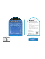
Figure 9. VHF Duplexer Field Tuning Procedure (Continued)
7.
Verifying Isolation
1.
Connect test equipment as
shown.
2.
Observe and note the level in
dBm as shown on the R2001 dis-
play.
3.
Connect the test equipment to
the duplexer as shown.
4.
Observe and note the level in
dBm as shown on the R2001 dis-
play. (If no number is displayed,
consider isolation to be greater
than 105 dB, which exceeds the
specification.)
5.
Subtract the absolute number
noted in Step 4 from the number
noted in Step 2. The difference
should be higher than 75 dB to
meet specification for Isolation.
6.
Repeat Steps 1-5 for Low- Pass/
High Notch cavities with the fol-
lowing exceptions:
a)
Set Frequency Generator
and R2001 for Rx or Tx
frequency, whichever is
HIGHER
b)
Connect Signal Generator to
Low Pass duplexer input
(cavity #1)
c)
Connect terminator to cavity
#6.
Frequency set to Rx or Tx frequency,
whichever is LOWER.
Output Level set to +10 dBm.
HP8656B Signal Generator
HP8656B Signal Generator
UG29A/U Bullet
Connector
Terminator
6dB In-line
pad (50
Ω
)
R2001 Communications
Monitor Function.
Center frequency set to Tx or Rx
frequency, whichever is LOWER
Attenuator set to –50 dBm
1
2
3
4
5
6
R2001 Communications
Attenuator set to 0 dBm
Содержание MTR2000 T5544
Страница 56: ...Description THIS PAGE INTENTIONALLY LEFT BLANK 68P81096E36 H 13 06 28 05 ...
Страница 160: ...VHF Receiver Module 6 68P81096E19 B 09 30 05 THIS PAGE INTENTIONALLY LEFT BLANK ...
Страница 167: ...VHF Exciter Module 6 68P81096E22 C 09 30 05 THIS PAGE INTENTIONALLY LEFT BLANK ...
Страница 259: ...DLN6622 500W Power Supply Module 6 68P81011Y31 O 03 10 06 THIS PAGE INTENTIONALLY LEFT BLANK ...
Страница 271: ...DLN6624 250W Power Supply Module 6 68P81011Y29 O 03 10 06 THIS PAGE INTENTIONALLY LEFT BLANK ...