


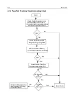


4-12
Maintenance
5V
at pin 6 of
D3701
Is information
from
µ
P U409
correct?
I s U 3 7 0 1
P i n 28 AT
4.54 VDC?
Is
U3701 Pin 47
approx.
13.3VDC?
Is U3801 Pin 19
<0.7 VDC in RX &
>4.3 VDC in TX?
Start
Visual
check of the
Board OK?
Correct
Problem
Check 5V
R e g u l a t o r
U3711
+5V at
U3701
Pin’s
13 & 30?
Is 16.8MHz
Signal at
U3701 Pin
19?
Check Y3762 and
associated circuitry
Are signals
at Pin’s 14 &
15 of U3701?
Check
L3701,
R3701
Check R3829
Is
U3701 pin 2 at
>3V in Tx and
<0.7V in Rx?
Remove
Shorts
Is there a short
between Pin 47 and
Pins 14 & 15 of
U3701?
Replace or
resolder
necessary
components
Is RF level at
U3701 Pin 32
>-30 dBm?
Are C3724, C3723,
R3721, R3722,
R3723 OK?
Replace
U3701
If R3727, C3726 & C3727
are OK, then see VCO
troubleshooting chart
Are Waveforms
at Pins 14 & 15
triangular?
Do Pins 7,8 & 9
of U3701 toggle
when channel is
changed?
Check programming
lines between U409
and U3701 Pins 7,8 & 9
Replace
U3701
Check uP U409
Troubleshooting
Chart
NO
YES
NO
YES
NO
YES
NO
YES
NO
NO
NO
YES
YES
NO
YES
YES
NO
YES
YES
YES
NO
NO
NO
NO
YES
NO
YES
YES
Check D3701,
D3702, U3701,
C3701 - C3707
3.3V at U3701
pins 5, 20, 34
& 36
Check U3201,
L3731
Is
16.8MHz
signal at
U3701 pin
23?
Replace
U3701
YES
NO
NO
YES
NO
YES
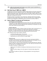
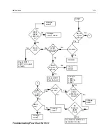
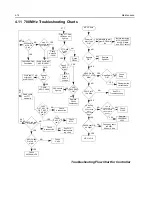
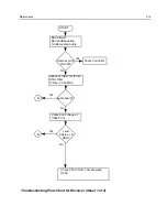
Troubleshooting Flow Chart for Synthesizer
Replace
U3701
Содержание HT1250-LS+
Страница 10: ...viii ...
Страница 12: ...x Product Safety and RF Exposure Compliance ...
Страница 16: ...1 4 Introduction ...
Страница 58: ...4 22 Maintenance ...
Страница 64: ...5 6 Schematic Diagrams Overlays and Parts Lists ...
Страница 102: ...5 44 Schematic Diagrams Overlays and Parts Lists Figure 5 34 Keypad PassPort Option Board Schematic Diagram ...