Theory of Operation
3-13
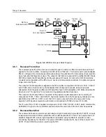
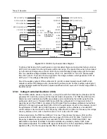
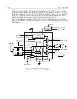
Figure 3-11. 700 MHz Receiver Block Diagram
3.9.1
Receiver Front-End
The received signal from the antenna is routed through the harmonic filter and antenna switch and
applied to the antenna filter FL300. This is a fixed-tuned 3-pole ceramic bandpass filter with a
passband of 744 MHz to 766 MHz and an insertion loss of 2.6 dB. The output of this filter is coupled
to RF amplifier Q301. Diode CR300 protects the RF amplifier by limiting excessive RF levels.
The output of the RF amplifier is applied to the RF amp filter FL301, identical to FL300. The output of
FL301 is connected to the passive double-balanced mixer consisting of components T301, T302, and
CR301. High-side injection from the frequency synthesizer is band-pass filtered by C317-324 and
L305-6 to remove second harmonic energy which may degrade half-IF spurious rejection
performance, and applied to T302 at a level of +8 dBm.
The IF output from T301 is applied to a diplexer (L303-4, C313-5 and R305) which matches the 73.35
MHz IF signal to the crystal filter and terminates the mixer into 50O at all other frequencies.
3.9.2
Receiver Back-End
The receiver back end is a dual conversion design. The 73.35 MHz high IF consists of 2-pole crystal
filter FL350, IF amp Q350, 2-pole crystal filter FL351 and IF amp Q351. Each crystal filter has a 3 dB
bandwidth of 9.0 kHz and a maximum insertion loss of 2 dB. The output of Q351 is applied to the
input of the receiver IFIC U350. Diode D350 prevents overdriving the IFIC.
The IFIC is a low-voltage monolithic FM IF system incorporating a mixer/oscillator, two limiting IF
amplifiers, quadrature detector, logarithmic received signal strength indicator (RSSI), voltage
regulator and audio and RSSI op amps. The second LO frequency is determined by Y350. Additional
IF selectivity is provided by two ceramic filters, FL352 (between the second mixer and IF amp) and
FL353 (between the IF amp and the limiter input). FL352 is a 6 element filter with a BW6 = 9 kHz.
FL353 is a 4 element filter with a BW6 = 12 kHz. These bandwidths are optimum for 12.5 kHz channel
spacing systems. Ceramic resonator Y351 provides phase vs. frequency characteristic required by
the quadrature detector, with 90 degree phase shift occurring at 455 kHz. Buffer Q352 provides a
lower driving impedance from the limiter to the resonator, improving the IF waveform and lowering
distortion.
Crystal
Filter
1st Mixer
RF
Amp
Antenna
Filter
RF Amp
Filter
Recovered Audio
RSSI
RX from
Antenna Switch
Inj Filter
First LO
from Synthesizer
IF
Amp
Crystal
Filter
IF
Amp
Demodulator
Ceramic
Resonator
Cer Fltr
Cer Fltr
4F
6G
Содержание HT1250-LS+
Страница 10: ...viii ...
Страница 12: ...x Product Safety and RF Exposure Compliance ...
Страница 16: ...1 4 Introduction ...
Страница 58: ...4 22 Maintenance ...
Страница 64: ...5 6 Schematic Diagrams Overlays and Parts Lists ...
Страница 102: ...5 44 Schematic Diagrams Overlays and Parts Lists Figure 5 34 Keypad PassPort Option Board Schematic Diagram ...


