background image


35 


7.4  Static overlays 


7.4.1  Introduction 


It is possible to overlay static overlays in the top view of the 
camera image. For example, danger areas, swivel ranges 
or support points can be displayed. 
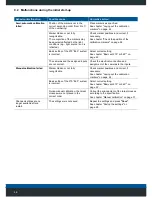
•  Various geometric figures can be displayed (point, line, 

circle, ellipse, triangle, rectangle, polygon). 

•  Transparent overlays are possible. 
•  Different colours and line thicknesses are adjustable. 
•  Selection between filled presentation or contour 

possible. 

•  Available in all top-views. 


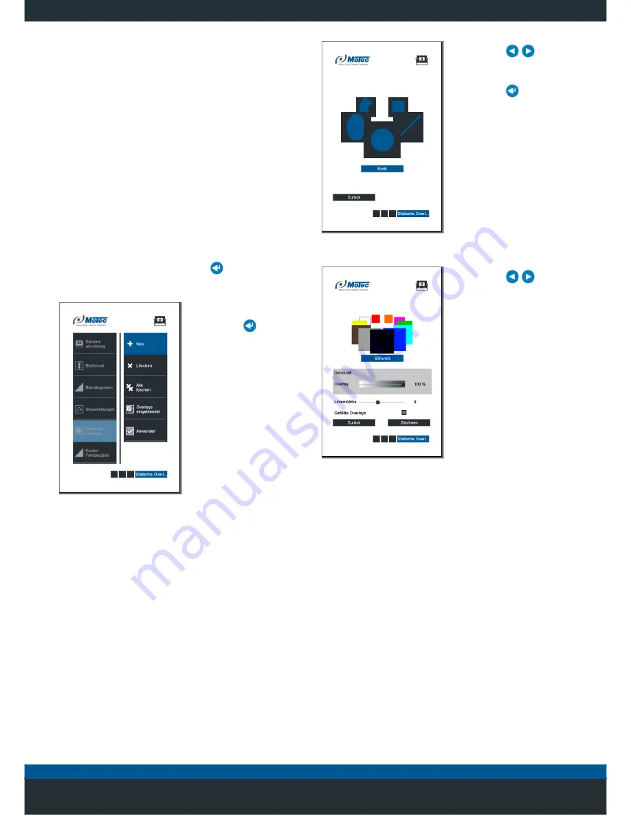
7.4.2  Configuration 


1. 

Select the menu “

... / Settings / Representation / 

Static overlays"


and press the 

 button to confirm 

the selection. 


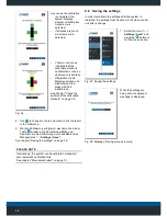
  2.  Select the 

New

 entry. 

3.  Use the 

 to confirm 

your selection. 


Fig. 39: New overlay 


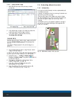
  4.  Use the 


 buttons 

to select the relevant 
shape. 

5.  Use the 

 to confirm 

your selection. 


Fig. 40: Selecting the shape 


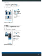
  6.  Use the 


 buttons 

to select the relevant 
parameter for the 
representation. 

7.  Use 

Draw

 to confirm 

the selection. 


Fig. 41: Selecting the representation 

Содержание MC7180N

Страница 1: ...Mobile Vicinity Scout MVS Installation instructions...

Страница 2: ...NY Phone 49 6433 9145 0 Fax 49 6433 9145 45 motec info ametek com www motec cameras com Copyright 2018 by Motec GmbH Subject to change without notice The document is protected by copyright It supports...

Страница 3: ...tive gear 11 3 System description 12 3 1 Package contents 13 3 1 1 MVS system 13 3 1 2 Service kit 13 3 2 Type signs 14 3 3 Technical Data 14 3 4 Components 14 3 4 1 Video control unit 14 3 4 2 Camera...

Страница 4: ...4 5 1 Switching on the system 20 5 1 1 Menu overview 21...

Страница 5: ...7 1 2 Blending 30 7 2 Manual calibration 31 7 3 Control lines 33 7 3 1 Introduction 33 7 3 2 Requirements 33 7 3 3 Configuration 34 7 4 Static overlays 35 7 4 1 Introduction 35 7 4 2 Configuration 35...

Страница 6: ...6 11 1 Disposal of packaging 52 11 2 Disposal of the products 52 12 Index 53...

Страница 7: ...mportant aspects of safety to ensure optimum protection of personnel and safe trouble free operation of the product The manufacturer cannot be held liable for damage resulting from non compliance with...

Страница 8: ...de the EU the user is required to comply with relevant national requirements If modifications are made to the device compliance with the requirements of conformity is no longer ensured and the warrant...

Страница 9: ...r the safe operation of the vehicle at all times This obligation applies in particular if personnel remain in the danger zone of the vehicle machinery 2 3 Non intended use Any use of other than that d...

Страница 10: ...ayed on the monitor as bending outward This representation which is not true to scale must be taken into account by the driver The display in the monitor is true to scale only on the footprint of the...

Страница 11: ...cian and the user have read and understood the instructions The operator and user are therefore responsible for ensuring correct use of the system Prior to driving the driver must proceed with a visua...

Страница 12: ...in the calibration range are displayed Inserting a customer specific vehicle image to ensure a display that is accurate to the contour of the vehicle Display of individual static overlays for the repr...

Страница 13: ...1x1 Heavy duty monitor MD3071A 1x MK723 connection cable Power supply 1x 1x MK772 connection cable Control lead for MVCD1000 x 1x 1x MK798 connection cable CAN cable for MVCD1001 x 1x 1x MK722 connect...

Страница 14: ...vant data sheets To download the data sheets of the components go to http www motec cameras com 3 4 Components 3 4 1 Video control unit Fig 4 MVCD1000 x MVCD1001 x The video control unit processes the...

Страница 15: ...m Monitor 360 or 270 system MD3071A V Vertical monitor alignment portrait format 270 system MD3071A Horizontal monitor alignment landscape format 3 4 4 Operator control unit Fig 8 MBE1000 operator con...

Страница 16: ...relevant side of the vehicle after the calibration In the case of vehicles which are subject to authorisation for the transport on public roads when the camera protrudes beyond the outer contour of t...

Страница 17: ...s body Improper and unsuitable drilling holes can damage the bodywork and cables Only drill in places without cable runs ensure to protect drill holes with corrosion protection CAREFUL Damage to cabl...

Страница 18: ...em Anschlussplan an die Steuereinheit an PLEASE NOTE When using a 360 system all four cameras are connected When using a 270 system only three cameras position C3 or C4 are connected As an option an a...

Страница 19: ...CAN1 Low 3 12 V DC 4 GND Flush mounted wall socket M12 4 pin A coded CAN2 operator control unit ultrasound sensors 1 CAN1 High 2 CAN1 Low 3 12 V DC 4 GND Flush mounted wall socket M12 4 pin A coded C...

Страница 20: ...of the button will also be displayed Back to the start menu home When pressed together with an arrow key it slows down the speed when aligning the calibration points and drawing overlays Changing the...

Страница 21: ...bed in the following chapters Getting started on page 22and Advanced features on page 29 Language English German French Settings Image Camera allocation Dimensions Image format Calibration Blending zo...

Страница 22: ...after a change See chapter Saving the settings on page 28 6 1 Language selection 1 Select the menu Language and press the button to confirm the selection 2 The relevant language is selected 3 Use the...

Страница 23: ...ger displayed at the real scale of the vehicle The system uses a different scale at in the horizontal and vertical direction approx 16 9 Thus a ball may suddenly appear to be oval rather than round 1...

Страница 24: ...each direction is required The doors and attachments e g exterior mirrors are closed or folded in PLEASE NOTE The positioning of the calibration markers in the 270 system is different for the front an...

Страница 25: ...6 5 3 Aligning the 360 system Fig 19 Marker positions in the 360 system 6 5 4 Aligning the 270 system Fig 20 Marker positions in the 270 front system Fig 21 Marker positions in the 270 rear view syst...

Страница 26: ...system requires the effective measurements between the calibration markers PLEASE NOTE The effective dimensions may differ from the dimensions of the vehicle When the position of the calibration mark...

Страница 27: ...ation must be repeated or the calibration must be carried out manually Selecting the blending process The standard setting for the overlap of the images of adjacent cameras are pre set at the factory...

Страница 28: ...ibrierung erfolgreich wechseln Sie mit der Taste wieder in die Benutzeroberfl che und Speichern sie die Kalibrierung durch Ausw hlen des Men punktes Settings Save See chapter Saving the settings on pa...

Страница 29: ...ce line is set automatically during calibration and is clearly visible in the composite image In this method objects or persons seem to disappear at the reference line This is caused physically as the...

Страница 30: ...y of the vehicle This effect can be avoided by choosing a different blending method 1 Select the menu Settings Representation Blending zones and press the button to confirm the selection 2 Select the...

Страница 31: ...ns is mandatory Deviations from the order result in incorrect image overlay incorrect or distorted representation The quality of the blended image in the blending zones depends decisively on the exact...

Страница 32: ...target crosses must be corrected 2 Use the arrow keys near the corresponding marker in order to position the active target cross 3 Use in order to activate the zoom function 4 Position the target cros...

Страница 33: ...to each control input In addition to the top view individual cameras can also be displayed in a split screen view or as a full screen For this purpose the control inputs are connected to the correspo...

Страница 34: ...4 Use the button to select the camera 5 Use the button to select the image format 6 Select Set to confirm the selection Fig 37 Camera and image format The display mode can be individually configured...

Страница 35: ...es are adjustable Selection between filled presentation or contour possible Available in all top views 7 4 2 Configuration 1 Select the menu Settings Representation Static overlays and press the butto...

Страница 36: ...cross on the diagonally opposite corner of the rectangle and press the key to confirm the selection PLEASE NOTE When pressing the or buttons simultaneously with the arrow keys while positioning the cr...

Страница 37: ...d Fig 47 Selecting the overlay 4 Use the arrow keys to select the overlay that must be deleted The selected overlay is displayed without transparency 5 Use the button to confirm the selection 6 In the...

Страница 38: ...s covered by the superimposed image By stretching the vehicle contour the distances between persons and objects with respect to the vehicle are scaled correspondingly 7 5 1 Configuration WARNING Risk...

Страница 39: ...background 2 Direction of view 7 5 2 2 Requirements Vehicle image according to the Chapter Requirements for the vehicle image on page 39 Laptop PC with SSH SCP Client Available Ethernet interface Mot...

Страница 40: ...lected network card 4 Select the Internet protocol version 4 TCP IPv4 item and click the Properties button Properties 5 Select Use the following IP address and enter the parameters indicated below IP...

Страница 41: ...ol select SCP 3 Enter the IP address 192 168 50 10 of the video control unit as the name of the computer host name Enter 22 as the port number 4 Enter the following parameters for user name and passwo...

Страница 42: ...esentation Contour of vehicle image and press the button to confirm the selection 6 If necessary configure the vehicle image Siehe Kapitel Configuration on page 38 7 Apply the settings with Apply and...

Страница 43: ...n how to install the MVCU 1300 1 can be found in the corresponding installation and operating instructions 7 6 3 Configuration In order to display the objects detected by the ultrasonic sensors in the...

Страница 44: ...e When using the value blind zone signals from stationary components on the vehicle e g trailer coupling can be suppressed PLEASE NOTE Within the blind range signals from objects or persons are also s...

Страница 45: ...m the selection 5 Press Back to leave the menu Fig 59 Selecting the overlay type PLEASE NOTE The overlay type Approximation arrows can only be used if the detection range of the ultrasonic sensors is...

Страница 46: ...riving the driver must proceed with a visual inspection and a functional test before using the system The display of objects on the monitor can be restricted in poor light conditions or strong sunligh...

Страница 47: ...tor display not available The green LEDs on the video control unit are lit Loose connectors monitor cable defective Check the monitor cable and connector for damage or tight fit Monitor defective Chec...

Страница 48: ...orrect setting See chapter Basic set 270 or 360 on page 22 The cameras and the assigned inputs are not correct Check the electrical connection and assignment of the cameras to the inputs Manual calibr...

Страница 49: ...les Check plug connector for tight fit Camera defective Replace camera Part of the image is shaking in the top view Attachment of the affected camera is loose Check the camera s bracket for a tight fi...

Страница 50: ...at oder nicht entzerrt The selection of the display mode for the control lead is not correct Check the display mode for the control lead correct the display mode if necessary See chapter Adjusting the...

Страница 51: ...he system and if necessary have it repaired Cable connection or sensor defective Check cable connection and plug connector Check sensors replace defective sensors with identical types No CAN connectio...

Страница 52: ...such as benzine paint thinner or other commercially available chemicals Stubborn stains can be removed with a damp window leather 10 2 Cleaning the camera lenses Dirty camera lenses provide a poor im...

Страница 53: ...allation of the MVCD control unit 15 Intended use 7 Introduction 7 L Language selection 21 Laying cables 15 M Maintenance 51 Manual calibration 30 Menu overview 20 N Non intended use 7 O Obligations o...

Страница 54: ...54...

Страница 55: ...Motec GmbH Oberweyerer Stra e 21 65589 Hadamar Steinbach GERMANY Tel 49 6433 9145 0 Fax 49 6433 9145 45 motec info ametek com www motec cameras com...

Отзывы: