24
6.5 Calibration
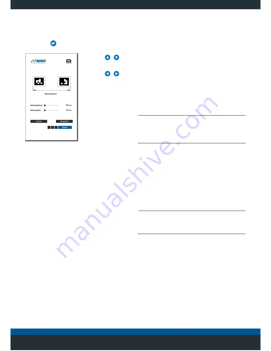
6.5.1 Basic setting Calibration marker size
1.
Select the menu “
... / Settings / Range / Tag
" and
press the
button to confirm the selection.
2. Use the
/
button to select the
relevant slider.
3. Use the
/
button to set the
applicable value.
• Set the
Distance of
the marker
(default 3.0 m).
• Set the
Marker size
(default 1.0 m).
4. Press
Apply
to confirm
the selection.
5. Press
Back
to leave
the menu.
Fig. 18: Setting the size of the marker
6.5.2 Laying out the calibration markers
In order to
optimise the blending of the cameras’ images, it
is necessary to calibrate the system using eight calibration
markers. The calibration markers allow the system to
detect the areas in which the images of the individual
cameras overlap.
Before laying out the calibration markers, follow the
instructions below:
• The size of the marker depends on the installation
height of the attachment and the length of the vehicle.
• The vehicle is parked in a straight line and the surface
it is parked on is flat.
• Around the vehicle, a clearance of 3 m in each
direction is required.
• The doors and attachments (e.g., exterior mirrors) are
closed or folded in.
PLEASE NOTE
The positioning of the calibration markers in the 270°
system is different for the front and rear view camera
systems.
Observe the orientation information for each version
shown in Fig. 20 and Fig. 21.
1. Lay out the calibration markers as shown in the
following illustrations.
2. Ensure the vehicle is parked on level ground.
3. Locate the calibration markers as close as possible to
the vehicle since the interior calibration markers form
the limit of visibility in relation to the vehicle.
4. Position the 1.5 m calibration markers immediately next
to each other. Position the 1 m calibration marker at a
distance of one metre apart.
PLEASE NOTE
Marker distance
The distance between the markers and the marker size
must be set in the "...
/ Settings / Dimensions / Marker
”
menu.
5. Compliance with the alignment and numbering of the
calibration marker is essential.
6. Use a suitable measurement to determine the
distances W and LThe dimensions must be stored in
the system for the later calculation of the distances.
Enter the dimension into the ”...
/ Settings /
Dimensions / Vehicle
" menu for the width of the
vehicle (
W
) and the length (
L
).
Содержание MC7180N
Страница 1: ...Mobile Vicinity Scout MVS Installation instructions...
Страница 4: ...4 5 1 Switching on the system 20 5 1 1 Menu overview 21...
Страница 6: ...6 11 1 Disposal of packaging 52 11 2 Disposal of the products 52 12 Index 53...
Страница 54: ...54...

