第 18 页 共 60 页
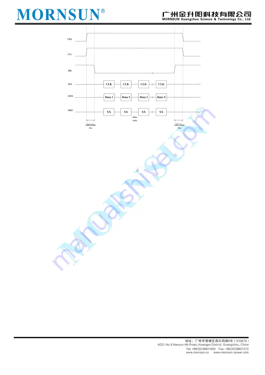
Figure 3.8 Schematic diagram of switching delay of host control function
3. Feedback mechanism
TD5(3)USPCAN only be used as an SPI slave, and can't actively control other SPI bus devices. If
TD5(3)USPCAN needs the master to check the status every time it receives the data sent by CAN, the
efficiency of the whole communication process will be very low, so we have added a feedback mechanism
for it. TD5(3)USPCAN has an INT feedback pin on the hardware, which is connected with the master. When
the following two situations occur, the INT pin will change from high level to low level, informing the master to
read data (to avoid data loss, it is recommended that the master use the falling edge trigger to detect):
(1) When the number of CAN frames in the CAN buffer reaches the set trigger point
When the number of CAN frames received in the receiving buffer of the product CAN bus reaches the
trigger point, the level of the INT pin is set low, and the INT pin will not return to the high level until the buffer is
cleared. Users can query the status of TD5(3)USPCAN after obtaining the INT signal, get the number of
readable bytes, and then read the buffer CAN data.
(2) When the CAN buffer data is less than the trigger frame number and the master does not read it
within the set time.
When the CAN buffer has data but less than the trigger frame number, if the bus has not added data for
a long time and the master has not read, the data in the CAN receiving buffer may not be processed for a
long time, which leads to low real-time performance of the data. In order to solve the real-time problem of a
small amount of data, TD5(3)USPCAN has a timer inside. If the data in the CAN buffer is not read within a
certain period of time, the INT pin will be triggered to be set low to inform the master to read the data. When
TD5 (3) USPCAN receives the last frame of data, the timer starts, and the timer is reset when the master reads.


