第 29 页 共 60 页
(standard frame) or 1 to 4 (extended frame), respectively. If the start address is set to 1 and the length is 2, the
1st and 2nd bytes in the serial frame (counting from 0) will be the CAN frame ID.
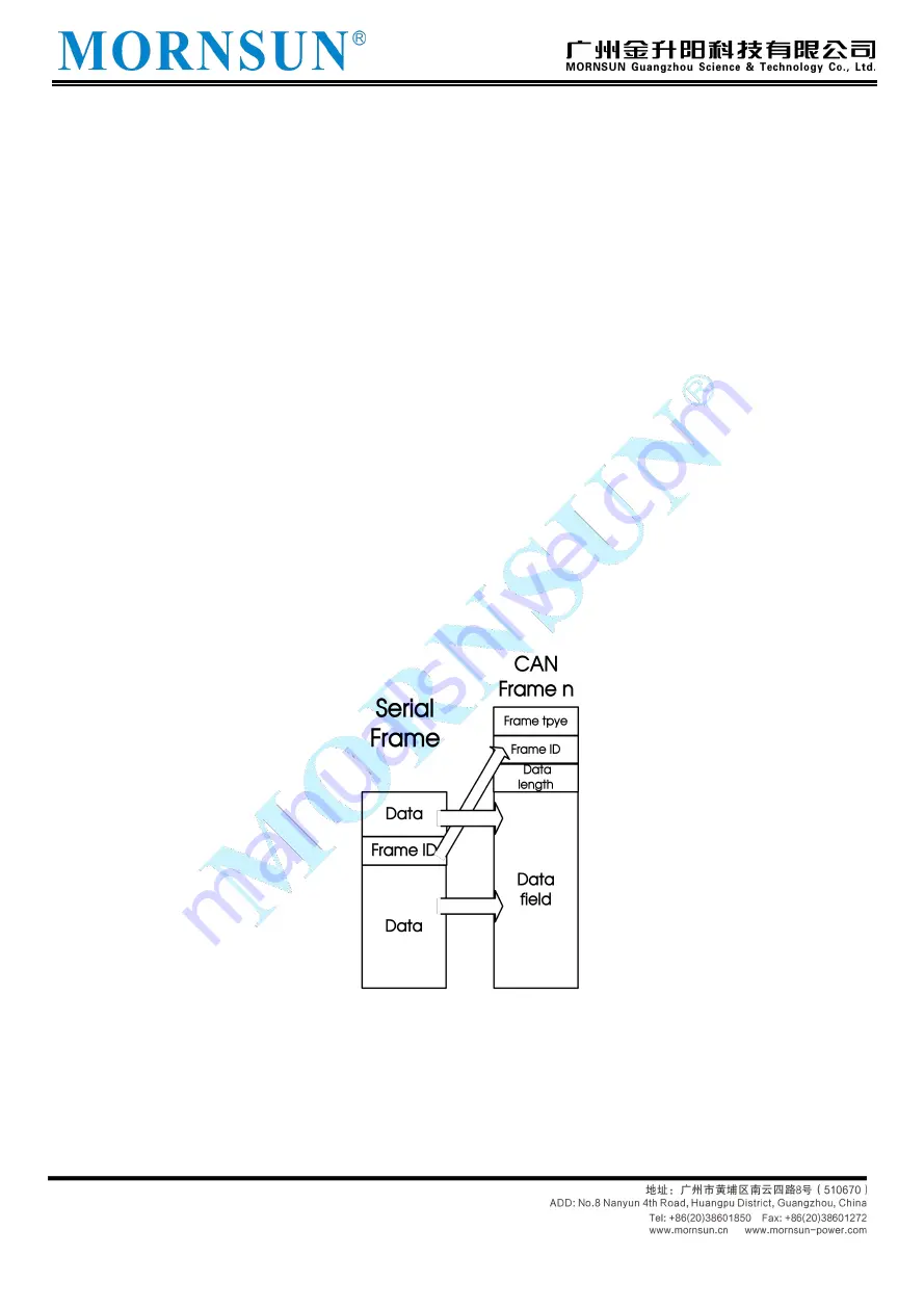
During the conversion, according to the user's configuration information, all the frame ID
correspondences of CAN frames in serial frames are converted into the frame ID field of CAN frames (if the
number of ID bytes is less than the number of frame ID bytes of CAN frames, then the filling sequence of CAN
frames is frames ID3
~
ID0, and the remaining IDs are filled with 0), and other data are sequentially converted,
as shown in Figure 3.21.
Because the maximum data length of CAN frame is 8 bytes, when the data length of serial frame is less
than or equal to 8 bytes, the data is forwarded through a CAN frame. If a CAN frame does not convert the
serial frame data completely, the same ID is still used as the frame ID of the CAN frame to continue the
conversion until the serial frame conversion is completed. The schematic diagram of data conversion is
shown in Figure 3.21. CAN frames only indicate the following useful information: frame type, frame ID, data
length and data field. In which CAN.
The "Frame Type" in the frame, the starting address and length of "Frame ID" in the serial frame are
determined by the user's configuration, and remain unchanged all the time unless the user reconfigures the
product again. The "data length" in the CAN frame is determined according to the actual number of bytes of
data allocated to the CAN frame.
Figure 3.21 Serial frame to CAN frame (transparent
generation identification conversion, data less than or equal to
8 bytes)


