


第 14 页 共 60 页
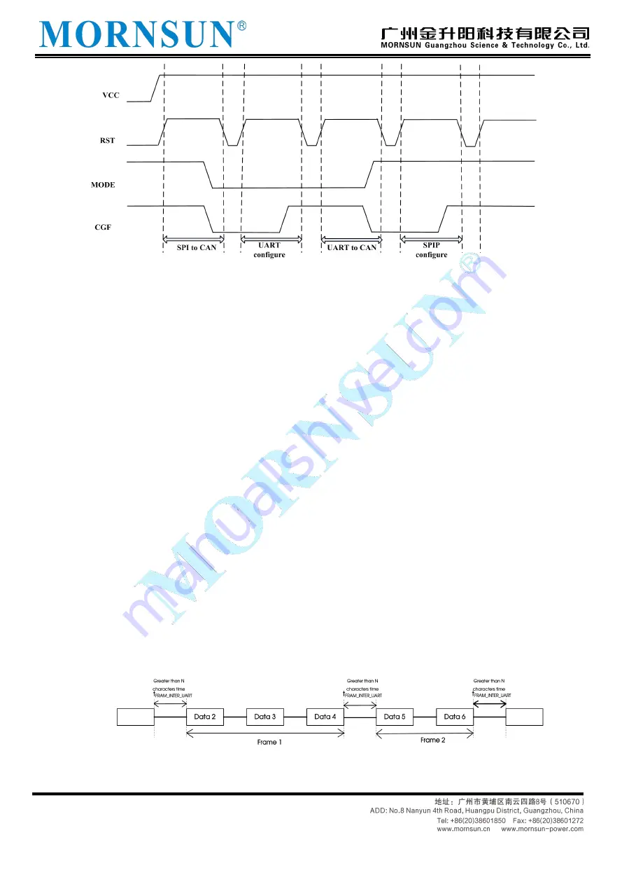
Figure 3.2 Schematic diagram of working mode switching
3.2.1 UART to CAN mode
In this mode, TD5(3)USPCAN can only send or receive data to CAN bus through UART. UART
communication format is fixed as: 1 start bit, 8 data bits and 1 stop bit, which cannot be changed.
Communication rate of UART ranges from 300 bps to 921600 bps. In this mode, the SPI interface is invalid, and
it will not process any data appearing in the SPI interface, nor will it return the data received by the CAN bus
to the SPI.
1. UART frame
From the moment UART receives the first data, until it waits for n characters (this parameter is set by the
user) before it receives new data, the data in this period is defined as one frame of data, and this period of
time is defined as "frame interval". Because the character time changes with the baud rate, the frame
interval time of the same number of characters is different under different baud rates. For example, the user
sets the UART frame interval to be 2 characters and the baud rate to be 9600bps. Since each character
consists of 10 bits, the interval time is 2 * 10/9600 = 2.083 ms. The first data on the bus represents the start of a
frame, and the last data before waiting for more than n characters is the last data of the frame; wait for
more than n characters and no new data appears, which means the end of a frame. UART communication
frame format is shown in Figure 3.3
Figure 3.3 UART Communication frame format diagram


