HIM
24
The Interface Solution Experts
Smart HART
Loop
Interface and Monitor
MODBUS Tab
The HIM PC program allows you to configure the
HART monitor. A HART Monitor with MODBUS out-
put provides a digital MODBUS output to a connected
MODBUS-based controller. Selecting the
MODBUS
tab allows you to set the MODSBUS communications
parameters. Notice that the
MODBUS
tab will only be
available in units with MODBUS configuration.
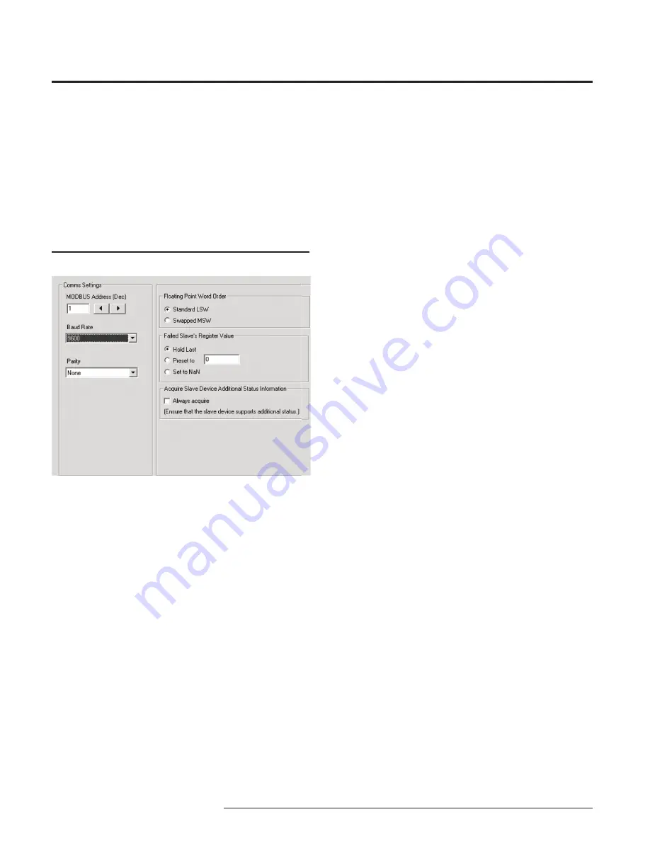
Comms Settings
The Comms Settings include the following:
MODBUS Address
The
MODBUS Address
is the number that the HIM
monitor uses to identify itself on the MODBUS net-
work. The MODBUS address is configurable from 1 to
247. By default, it will assume a MODBUS address of
01.
Baud Rate
The
Baud Rate
is the speed of data transmission. It
should be set to match the baud rate of the attached
controller. The interface supports the following baud
rates: 300, 600, 1200, 2400, 4800, 9600 and 19200.
Parity
The HART monitor supports even, odd and no
Parity.
The data format is one start bit, 8 data bits and one
stop bit.
Floating Point Word Order
Figure 18.
MODBUS Tab
By default, the HART monitor will use the
Standard
LSW
(least significant word) floating point word order
format. This stores the most significant bits in the
second register and the least significant bits in the first
register. Selecting
Swapped MSW (most significant
word)
will reverse the order, storing the most signifi-
cant bits in the first register and the least significant
bits in the second register.
Failed Slave’s Register Value
You may select what would occur to a slave device’s
register value in the event that communication is lost
with the HIM.
If selecting
Hold Last
and a failure is detected, the last
measured value before the failure occurred is held.
Entering a user-set value in the
Preset to
text box re-
calls that value when a slave device failure is detected.
Selecting
NaN
(Not a Number–as put forth by the
IEEE-754 standard) causes the floating point NaN
value to be stored in the registers used for holding
floating point values.
Acquire Slave Device Additional Status Informa-
tion
Checking the
Always acquire
box will allow the Ad-
ditional Status information to be displayed in the cor-
responding MODBUS register (refer to Table 3). If the
box remains unchecked, Additional Status information
will be unavailable.
If this information is not needed, it is good practice to
keep the box unchecked in order to keep polling of the
additional status bytes from occurring. This will help
maintain faster response times.
MODBUS Registers
The HART Monitor outputs a MODBUS signal to the
attached controller. To access the MODBUS registers
for variable, input/output or error information, refer to
Tables 3 and 4 for more information.


