


67
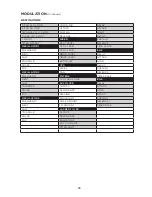
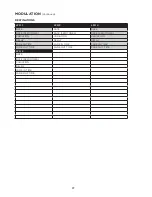
MODULATION
In basic terms, modulation allows a control signal from one module to influence the value of a
parameter in another module. A modulation path needs both a source and a destination. In a truly
modular world, each modulation pathway is created by connecting a separate patch cord from the
modulation source to the destination – often side stepping along the way to invert the value, to
add a controller, or to use a multiple (Mult.) jack to carry the signal to multiple destinations. Cyclic
modulation sources (such as LFOs) generate excellent control signals for adding vibrato and tremolo.
Envelopes can deliver multi-segment control signals that evolve to shape a sound over time. This is
the crux of modular synthesis. Moog One can create, catalog, save, and maintain countless modulation
pathways, adding greatly to the precision, depth, and animation of the final sound.
Moog One employs three basic means for addressing modulation: Hard-Wired; Quick Assign; and the
unparalleled Modulation Matrix.
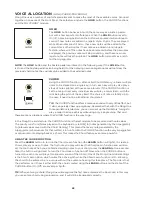
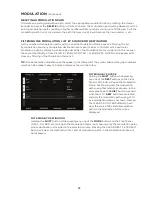
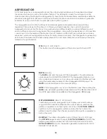
HARD-WIRED MODULATION
Some modulation pathways are so common and well established in the world of synthesis and sound
design that Moog One offers their immediate control using dedicated hardware. These hard-wired
modulation controls appear along the bottom portion of the individual Oscillator modules, and in the
lower portion of the Filter modules. These shortcuts should in no way be seen as limiting to the user;
any of these modulation sources and destinations can be connected in new and different ways using
the expansive Modulation Matrix.
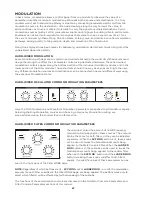
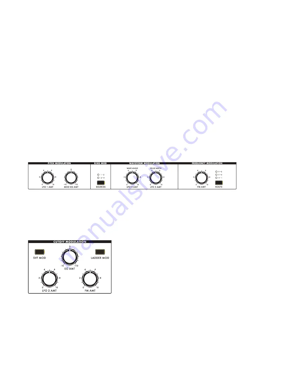
HARD-WIRED OSCILLATOR COMMON MODULATION PARAMETERS
Here, the Pitch Modulation and Waveform Modulation parameters are applied to all Oscillators equally.
Selecting the Ring Modulation sources and choosing a Frequency Modulation routing are
also performed using the controls found in this section.
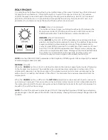
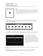
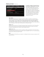
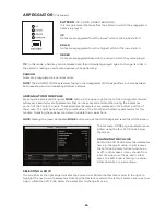
HARD-WIRED FILTER COMMON MODULATION PARAMETERS
These knobs control the amount of Cutoff Frequency
modulation being applied by these sources. The amounts
can be the same for both filters, or they can be adjusted
separately. When the
SVF
MOD
button is lit, these knobs
can be used to tweak the modulation amounts being
applied to the State Variable Filter. When the
LADDER
MOD
button is lit, these knobs can be used to tweak the
modulation amounts being applied to the Ladder filter.
When both the
SVF
MOD
button and the
LADDER
MOD
button, tweaking these knobs will affect both filters
equally. The specific values of these parameters can be
seen in the right pane of the Filter MORE page.
NOTE:
Regardless of which buttons are lit -
SVF MOD
and/or
LADDER MOD
- or unlit, the modulation
amounts for each filter, specified in the Filter MORE page, are being applied. The buttons work only to
select which filter(s) will be affected by further tweaking of these knobs.
The functions of these modulation controls are discussed in the Oscillator Common Parameters and
Filter Common Parameters sections of this manual.
Содержание One
Страница 2: ......
Страница 6: ...This page left intentionally blank ...
Страница 103: ...103 This page left intentionally blank ...
Страница 113: ...113 This page left intentionally blank ...
Страница 127: ...127 This page left intentionally blank ...
Страница 146: ...146 ...


