


5.6.1 Synchronous motor identification (rotary and linear)
Enter the motor data.
Click "Identification" button
Current controller tuning:
optimization of the current controller is done
automatically.
5.6.2 Asynchronous motor identification
Current controller tuning
Measurement of:
P 470[0] - MOT_Rstat
: Stator resistance,
P 476[0] - MOT_
Rrot
: Rotor resistance,
P 471[0] - MOT_Lsig
: Leakage inductance
Maximum effective current Idmax
P 474[0] - MOT_LmagIdNom
Calculation of the working point:
P 462[0] - MOT_FluxNom
: Nominal flux,
P 340[0] - CON_FM_Imag
: Magnetizing current
Calculation of: Current, speed, and position control parameters
Click the "Start calculation" button to determine the rotor resistance
P 476[0] -
MOT_Rrot
and leakage inductance
P 471[0] - MOT_Lsig
.
Measurement of the saturation characteristic (table values for stator
inductance
P 472 - MOT_LSigDiff
);
M
easurements
are
taken up to four times rated current, provided the
power
stage current
permits it at standstill
. If this is not the
case, the measurement is
made using a correspondingly smaller current.
P 340[0] - CON_FM_Imag
Magnetizing current
MOOG
ID
No.:
CB40859-001
Date:
02/2018
MSD Servo Drive - Device Help
45
5 Motor
5.7 Support for motor filters when using PMSM
motors
5.7.1 General functional description
In applications involving high-speed drives in particular, the use of filters between
the inverter output and the motor is widespread as a measure designed to attenuate
current harmonics. The following two are used for this purpose:
Motor chokes
LC filters, also referred to as “sine wave filters”
A motor choke basically increases the stator inductance and, in the case of current-
controlled drives, simply results in a higher inductive voltage consumption.
Accordingly, it is not necessary to take motor chokes into account separately when
calculating current setpoints.
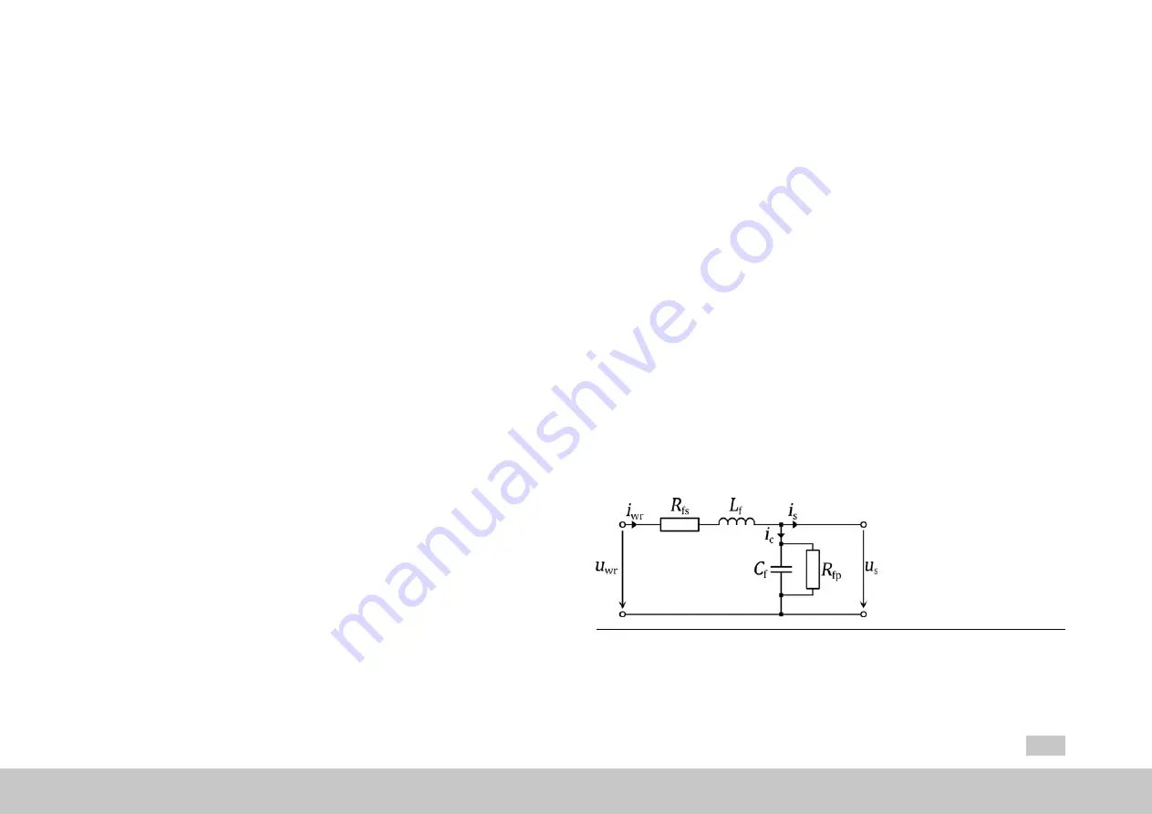
Meanwhile, as a result of the additional capacitor current (
i
c
) resulting from their use,
sine wave filters result in a change to the current vector between the inverter output
(
i
inv
) and the motor (
i
s
). Accordingly, these filters must be taken into account when
calculating current setpoints in order to ensure that the motor will be run at the
desired operating point (normally with q current operation) at all speeds.
Fig. 5.14: Single-phase equivalent circuit diagram for a sine wave filter
Содержание MSD Servo Drive Series
Страница 3: ...MOOG ID No CB40859 001 Date 02 2018 MSD Servo Drive Device Help 3 Change history...
Страница 4: ...MOOG ID No CB40859 001 Date 02 2018 MSD Servo Drive Device Help 4 Change history...
Страница 14: ...MOOG ID No CB40859 001 Date 02 2018 MSD Servo Drive Device Help 14 1 General information...