XG0523 - 170223
43
Operation
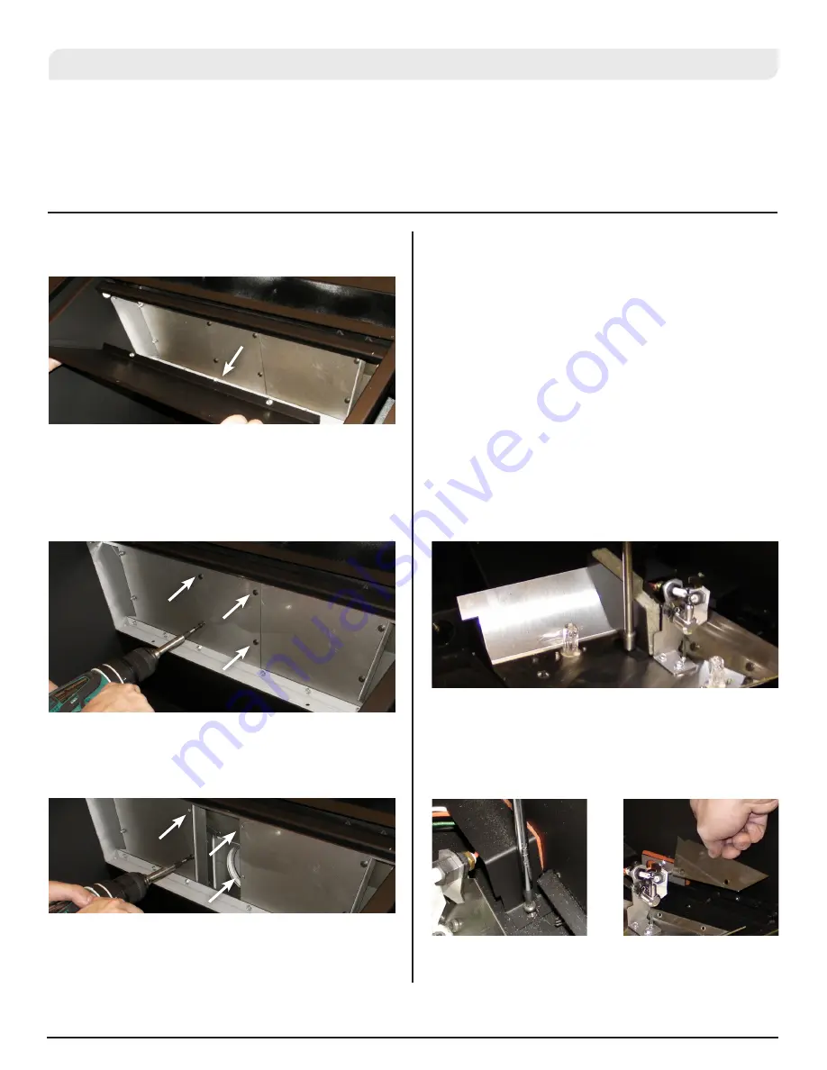
Figure 10.17
Figure 10.20
Figure 10.18
Figure 10.19
Pilot Maintenance / Replacement
We suggest throughout this manual that maintenance on this product
should be performed yearly. This is the best practice in order to keep
your fireplace insert running reliably for many years to come. One of
the items that should be inspected yearly and may need service is the
Pilot Burner Assembly. The Pilot Burner Assembly is responsible for
lighting the appliances and provides the safety mechanism to ensure
that the appliance performs safely. In order to service the pilot, the
Door, Burner Assembly, Log set etc. must first be removed. There are
specific sections in the manual that cover those procedures. Replacing
the pilot can be performed with the following steps.
1. Disconnect Gas and Electrical Supply to the Appliance. You will
need to have the unit outside the install to access the Valve
location. If the unit has already been installed, see the sections
on removing the Faceplate Panels and Vent Connections.
2. Remove the Firebox Panels and Burner Assembly (see
appropriate sections)
3. Remove the 2 heat shields and insulation that cover the pilot
assembly.
5. The Firebox Baffle can be lowered at the front and then pulled
forward away from 2 studs that secure the rear.
6. Remove the 4 screws that secure the bypass plate to the bottom
of the Heat Exchanger.
CAUTION: Screws may be tight. Use WD40 to help reduce the risk
of screws stripping or breaking heads.
7. Once the Restrictor has been removed, it is important that you
return the screws to their locations again.
8. Re-install the Firebox Baffle, left and right Upper Firebox Panel
Retainers, Firebox Panels and Burner assembly and door.
4. Remove the screw
securing the pilot wire
cover and remove pilot
wire cover.
5. Remove the 2 screws
securing the right side
of the light reflector and
remove part.
Figure 10.21
Figure 10.22


