6
PRODUCT OVERVIEW
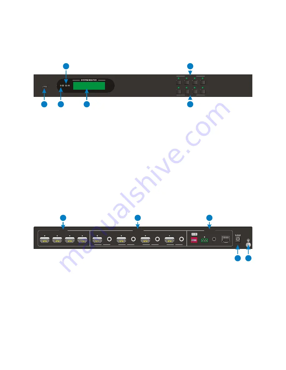
Front Panel
1.
FIRMWARE: Micro USB port for performing firmware updates.
2.
POWER LED: The LED illuminates red when power is on. It illuminates green when in
standby mode and flashes red when upgrading the firmware.
3.
IR: IR "eye" for receiving signals from the included IR remote control.
4.
SYSTEM MONITOR: LCD screen displays the real-time connection status.
5.
INPUTS: Four buttons for selecting the input source.
6.
OUTPUTS: Four buttons for selecting the output channel.
Rear Panel
1.
INPUTS: Four HDMI® jacks for connecting the source devices.
2.
OUTPUTS: Four HDMI jacks for connecting the displays and four digital coaxial
S/PDIF jacks for connecting an external amplifier or receiver.
3.
CONTROL: DIP switches for setting manual EDID management. RS232 connector for
connecting to a computer for RS232 control. 3.5mm IR IN jack for connecting the
included IR receiver. RJ45 jack for TCP/IP control using the built-in web-based GUI.
4.
DC 24V: DC barrel connector for connecting the included AC power adapter.
FIRMWARE
INPUTS
OUTPUTS
1
2
3
4
1
2
4
6
3
5
1 2 3 4
ON
DIP
INPUTS
OUTPUTS
CONTROL
SPDIF
SPDIF
SPDIF
SPDIF
1
2
3
4
1
4
2
3
On
Off
1 2 3 4
1
0
Tx
Rx
TCP/IP
EDID
IR IN
R S232
DC 24V
4
5
1
2
3


