01/02 AWB8230-1413GB
Electrical connection
39
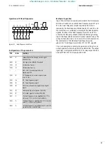
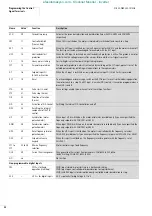
Function of the control signal terminals
Table 7:
Meaning of the control signal terminals
No.
Function
Level
WE
Technical data, description
Supply voltages
H
Setpoint voltage output
+10 V
H
–
Supply voltage for external setpoint potentiometer.
Load carrying capacity: 20 mA
Reference potential: Terminal L
P24
Control voltage output
+24 V
H
–
Supply voltage for actuation of digital inputs 1 to 5
and FW.
Load carrying capacity: 100 mA
Reference potential: Terminal CM1
Reference potentials
CM1
Reference potential
0 V
–
Reference potential terminals 1 to 5, FM, FW,
TH and P24
L
Reference potential
0 V
–
Reference potential, terminals AM, AMI, H, O,
OI and O2
PLC
Common connection,
terminals 1 to 5 and FW
By default, the frequency inverters are supplied with a link between PLC and CM1, so that the potential on terminal
PLC – and therefore on the digital inputs that are not energized – is 0 V (positive logic). If PLC is applied to P24,
the control logic is positive.
Digital inputs
1
Digital input
HIGH = +12 to +27 V
LOW = 0 to +3 V
RST = reset
PNP logic, configurable,
R
i
= 4.7 k
O
Reference potential: Terminal CM1
2
AT = analog input changeover
3
FF2 = fixed frequency 2
4
FF1 = fixed frequency 1
5
REV = anticlockwise operation
FW
Digital input, clockwise
operation
–
R
i
= 4.7 k
O
Reference potential: Terminal CM1
Analog inputs
O
Analog input
0 to +10 V
H
Frequency setpoint value
(0 to 50 Hz)
R
i
= 10 k
O
Reference potential: Terminal L
OI
Analog input
4 to 20 mA
Frequency setpoint value
(0 to 50 Hz)
R
B
= 250
O
Reference potential: Terminal L
O2
Analog input frequency
setpoint
–10 V to +10 V
H
–
Resolution: 12-bit
Input impedance: 10 k
O
Reference potential: Terminal L
TH
Thermistor input
–
Minimum thermistor rating: 100 mW
Reference potential: Terminal CM1
efesotomasyon.com - Klockner Moeller - inverter


