Operation & Maintenance, Page
4
of
23
Section
3
– Revision 2.3
SIZER™ Start-Up Procedure
m
Carry out the specified pre-start checks.
m
The machine can now start. If the motor starts, but the shafts do not rotate, then the machine is either stalled, or a
fusible plug has melted in one or both of the fluid couplings.
m
Refer to the
Stall Procedure
.
Overload Safety Systems
(Mechanical)
m
Mechanical overload protection is given by use of a fluid coupling, mounted on the input shaft of the gearbox and
the drive shaft motor.
m
The fluid coupling is protected against excessively high operating temperatures by built-in fusible plugs, which melt
on thermal overloading, and allow the fluid to discharge, thereby interrupting the transmission of torque and prevent-
ing damage.
m
After a fusible plug failure, the fault must be corrected. The peripheral bolts must be re-torqued, (see fluid couplng
section), new fusible plugs fitted, and the fluid coupling refilled with clean fluid in accordance with the fluid cou-
pling manual.
m
160/140/180
ºc
. For normal use the 160
ºc
type fusible plug should be used.
Overload Safety Systems
(Electrical)
m
Where specified, fitted at the non drive end of the SIZER™, is an underspeed sensing device. The purpose of the under-
speed sensing device is to isolate power to the main SIZER™ motor(s) and upstream supply systems. When the rotors
have lost speed. This is achieved by a pulse stud on the breaker shaft(s) passing through the magnetic field of a close
proximity sensor, therefore inducing an electrical impulse to the monitoring system. Should the breaker shafts stop ro-
tating, the monitoring systems should be connected to ensure they trip the electric motor(s) after seven seconds.
The
Power supply to the electric motor(s) must be isolated
, and a manual inspection can be carried out to identify the fault.
Replacing The Underspeed Sensor
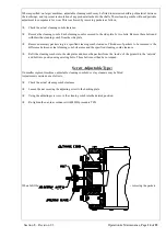
Should the underspeed sensor become inoperative, it will be necessary to replace it. To do this the machine must be isolated
electrically together with any upstream supply systems, so that they cannot be started accidentally whilst work is being carried
out.
i
Isolate power supply.
i
Disconnect electric leads.
ii
Loosen the locknuts, and unscrew the detector head.
iv
Refitting is the reverse of the above procedure. However, care must be taken to ensure that the sensor head is
within 5 to 10mm of the stud in the end of the breaker shaft, which provides a pulse every revolution.


