Underspeed Sensing Assembly, Page
6
of
7
Section
9
– Revision 1
III. MAINTAINED RUN CIRCUIT OPERATION
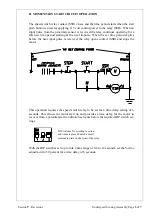
The speed switch relay contact (SSR) closes and the time period starts when the con-
trol switch is in the run position, applying 115 volt control power to the relay (SSR).
When and input pulse from the proximity sensor is received the relay continues oper-
ating for a full new time period starting at the next input pulse. When the set time
period expires before the next input pulse is received, the relay opens contact (SSR)
and stops the motor.
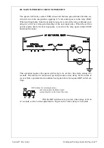
This operation requires the speed switch relay to be set for a time delay setting of 6
seconds. This allows for motor start up and provides a time delay for the motor to
recover from a potential stall condition. See figure below for required DIP switch set-
tings.
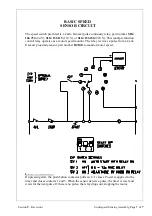
DIP switches for selecting function
and time are placed behind a small
removable plate on the front of the relay.
With the DIP switches set to provide a time range of 0.6 to
12 seconds, set the % time adjustment to 50 percent for a time delay of 6 seconds.

