background image

MMD MINING MACHINERY DEVELOPMENTS LIMITED

Centralised Greasing Assembly, Page 

1

 of 

2

Section 

– Revision 1

CENTRALISED GREASING

ASSEMBLY

PART NUMBER - 146251983

REVISION

MODIFICATION

DATE 

1.0

FIRST ISSUE

14-12-00

Содержание TWIN SHAFT SIZER 625 Series

Страница 1: ...sed Greasing Customer Supply Underspeed Sensing Carlo Gavazzi 110V A C Please quote in all correspondence This number can be found on the identification plate and welded onto the machine side plate INSTALLATION OPERATION SPARE PARTS AND MAINTENANCE MANUAL MMD Mining Machinery Developments Limited THE MMD GROUP OF COMPANIES MMD 625 SERIES 625MM CENTRES TWIN SHAFT SIZER S625 0085 Standard Height Len...

Страница 2: ...D JOB NUMBER 15464 MACHINE SERIAL NUMBER S625 0085 GEARBOX SERIAL NUMBERS S7070435 019 S7070435 020 G A DRAWING NUMBER 6250424 Company Registration Nº 1382580 CUSTOMER ANGLO COAL GOEDEHOOP COLLIERY SOUTH AFRICA MMD 625 SERIES 625MM BREAKER SHAFT CENTRES TWIN SHAFT SIZER AB ...

Страница 3: ...ASSEMBLY Section 2 OPERATION MAINTENANCE Section 3 SIZER CASE ASSEMBLY Section 4 GEARBOX ASSEMBLY Section 5 MOTOR FLUID COUPLING ASSEMBLY Section 6 WHEEL CARRIAGE ASSEMBLY Section 7 AUTO LUBRICATION ASSEMBLY Section 8 UNDERSPEED SENSING ASSEMBLY Section 9 ...

Страница 4: ...ear Coupling Assembly Page 24 25 GEARBOX ASSEMBLY SECTION 5 Gearbox Case Assembly Page 2 8 Input Shaft Assembly Page 9 10 2nd Reduction Shaft Assembly Page 11 3rd Reduction Shaft Assembly Page 12 4th Reduction Shaft Assembly Page 13 Output Shaft Assembly Page 14 MOTOR FLUID COUPLING ASSEMBLY SECTION 6 Motor Fluid Coupling Assembly Page 2 3 WHEEL CARRIAGE ASSEMBLY SECTION 7 Wheel Carriage Assembly ...

Страница 5: ...Y DEVELOPMENTS LIMITED General Arrangement Drawing Page 1 of 2 Section 1 Revision 1 MMD 625 SERIES 625mm CENTRES TWIN SHAFT SIZER General Arrangement Drawing No 6250424 REVISION MODIFICATION DATE 1 0 FIRST ISSUE 14 12 00 ...

Страница 6: ...MMD MINING MACHINERY DEVELOPMENTS LIMITED SIZER Assembly Page 1 of 3 Section 2 Revision 1 SIZER ASSEMBLY SERIAL NUMBER S625 0085 REVISION MODIFICATION DATE 1 0 FIRST ISSUE 14 12 00 ...

Страница 7: ...MMD MINING MACHINERY DEVELOPMENTS LIMITED SIZER Assembly Page 2 of 3 Section 2 Revision 1 SIZER Assembly Serial Number S625 0085 ...

Страница 8: ... 4 Tooth x 8 Ring 2 538 1 5 246251957 Right Hand Heavy Duty Shaft Assembly 4 Tooth x 8 Ring 2 538 1 6 145060084 Heavy Duty Tooth Cap Fixings Assembly 23 6 64 7 111701004 Gear Coupling Assembly 109 2 8 247070435 MMD R200 30 1 Ratio Gearbox Assembly 1 758 2 9 146251966 Voith 487 TV Fluid Coupling Assembly 581 2 10 145040240 Wheel Carriage Assembly 1 757 1 11 146251983 Centralised Greasing Assembly 2...

Страница 9: ...ERY DEVELOPMENTS LIMITED Operation Maintenance Page 1 of 23 Section 3 Revision 2 3 MMD 625 SERIES TWIN SHAFT MINERAL SIZER PRINCIPLES OF OPERATION MAINTENANCE SCHEDULE REVISION MODIFICATION DATE 1 0 FIRST ISSUE 14 12 00 ...

Страница 10: ...ined sideframes are of ribbed construction fabricated from structural steel with easily replaceable steel wearplates covering all the inside area of the sizing chamber Suitable drillings readily accept the fitting of hopper and chute work The main shafts are machined from high strength alloy steel bar which are supported by self aligning double row spherical roller bearings which are situated in h...

Страница 11: ... S OWN RISK Commissioning Procedure If the SIZER is removed from the working position for major overhauls or modifications it will also be necessary to re commission it prior to re starting m Carry out a full check of all items against manual parts list and drawings to ensure that everything is installed cor rectly This is a visual check only m Carry out a stall test to adjust the level in the flu...

Страница 12: ...ical m Where specified fitted at the non drive end of the SIZER is an underspeed sensing device The purpose of the under speed sensing device is to isolate power to the main SIZER motor s and upstream supply systems When the rotors have lost speed This is achieved by a pulse stud on the breaker shaft s passing through the magnetic field of a close proximity sensor therefore inducing an electrical ...

Страница 13: ...ol switch and run the motor until a steady speed reading is obtained on the tachometer It is imperitive that running time is kept to a minimum to avoid a build of thermal energy in the coupling ii Stop the motor iii The objective is to obtain a steady reading of approximately 94 of synchronous motor speed i e 50Hz 1410 RPM 60Hz 1700 RPM iv Add or remove a small amount of fluid as required v Allow ...

Страница 14: ...e cause of the noise The obvious causes would be faulty bearings in the motor fluid coupling or gearbox lack of lubricant or ingress of dust into rotating parts VIBRATION A similar check list is used as when tracking down an unusual noise however most excessive vibration is caused either by faulty main shaft bearings or faulty gearbox bearings These items should be checked first by checking the te...

Страница 15: ...to each wear plate on smaller machines this procedure may not be necessary m Remove the bolts retaining the side wear plates and pyramids to the side plates and discard them m Attach lifting equipment to the lifting lugs m Remove the bolts retaining the side wear plates and discard them m Remove the wear plate m Thoroughly clean the inside of the machine where the new wear plate is to be fitted to...

Страница 16: ...ed holes m Fit lifting eye bolts into the top of the wear plates and lift out m Thoroughly clean all faces to which the new wear plates fit to ensure correct seating of the new wear plate Protect tapped fixing holes before cleaning m Attach lifting eye bolts to the new wear plate and lift it into position m Bolt the wear plate into position using the existing set screws m Remove the lifting eyes m...

Страница 17: ...there is any sign of damage the seals must be replaced As company policy MMD recommend that all seals be replaced if they are removed for any reason m SEAL SPACER If there is any grooving on the outside diameter of this spacer it must be replaced m BEARING CAPSULE If there is any obvious damage or any sign that the bearing has been turning in the capsule then it should be replaced Main Shaft Beari...

Страница 18: ...ssembly may now be dismantled as follows i Remove the retaining plate This automatically removes the two outer seals and the seal spacer ii Support the bearing capsule around the periphery 200mm off floor level iii Apply heat to the outside of the bearing capsule iv The damaged bearing should fall out of the capsule Things to Check m LABYRINTH Check for wear grooves on the seal surface Also check ...

Страница 19: ...o C Remove from the oil bath and immediately push onto the shaft Care must be taken as the seals engage the labyrinth spacer and the assembly must be eased into position The assembly will seat fully home once engaged onto the seal surface of the labyrinth spacer as the furthest extremity of the labyrinth locates against the inner race of the bearing m Fit one of the bonded seals into the dowel loc...

Страница 20: ...ly sized eye bolts lift out the top bearing housings The shaft assemblies are now exposed m The damaged shaft can now be lifted out by means of nylon webs slung at either end m Once the shaft is removed the bearing assemblies and labyrinth seals can be removed refer to the bearing removal sections m Replacement is a reversal of the above procedure Shaft Re Timing Procedure Where the machine is fit...

Страница 21: ...able the end wear plate and refit the bolts which secure it to the case Breaker Bar Adjustment Adjustment of the breaker bar should be carried out as follows m Remove the bolts securing the breaker bar to the machine m Using the jacking screws raise the breaker bar to the desired height m Adjust the breaker bar by removal insertion of packers as required m When the height is satisfactory refit the...

Страница 22: ...kness of packers to be removed is the difference between actual cleaning comb clearance and the specified cleaning comb clearance m Refit the cleaning combs into the side plates and move the packers from the inside of the pyramid to the outside and bolt into position using existing bolts These bolts must then be re torqued Screw Adjustable Type On smaller segment machines adjustable cleaning combs...

Страница 23: ...emove necessary packers to give desired cleaning comb clearance If the infill box needs to be moved out wards in order to fit additional packers it is recommended that lifting equipment be attached to aid in this operation m Refit the existing bolts replace with new bolts if too short which secure the infill box to the side plate These bolts must then be re torqued as stated in T056 ...

Страница 24: ...removing the following procedure should be followed m Disconnect all electrical connections from the motor m Remove the cover plate s from the motor mounting frame m Remove the bolts connecting the motor flange and bolts connecting the motor feet to the mounting bracket mThe motor can now be removed Carefully slide the motor out of the motor mounting bracket until the drive boss on the motor shaft...

Страница 25: ...oring System must be removed from the gearbox m Remove the motor mounting bracket or coupling housing from the gearbox m Remove the top cover plate to expose the gear coupling m Split the two clamping rings from the gear coupling taking care not to damage the O ring m Slide the coupling sleeve towards the gearbox m Attach lifting equipment to the gearbox lifting eyes m Remove the studs bolts conne...

Страница 26: ...ate Fit the studs bolts connecting the gearbox to the gearbox mounting plate and torque to the amount specified in MMD procedure T056 m Align the teeth on the coupling half with the teeth on the coupling sleeve and slide the coupling sleeve into position m Ensure O rings are correctly seated on the coupling sleeve and fit the two split clamping rings around the coupling Tighten bolts in accordance...

Страница 27: ...The Fluidrive fluid coupling may now be removed See fluidrive installation and operating instructions before remov ing the coupling Installation m Clean the gearbox input shaft m Fit the Fluidrive coupling in accordance with fluidrive s installation and operating instructions MMD Equipment Storage Instructions All MMD equipment is delivered in a stored condition and is suitable to be stored inside...

Страница 28: ...rt Up VOITH DESIGN TYPE TV 1 Flexible Connecting Cpl g 6 Filler Plug 2 Outer Wheel 7 Fusible Plug 3 Coupling Shell 8 Operating Fluid 4 Inner Wheel 9 Delayed Filling Chamber 5 Coupling Hub 10 Delay Nozzle Coupling Running VOITH DESIGN TYPE TVSC 6 Filler Plug 1 Flexible Connecting Cpl g 7 Fusible Plug 2 Outer Wheel 8 Operating Fluid 3 Coupling Shell 9 Delayed Filling Chamber 4 Inner Wheel 10 Delay C...

Страница 29: ...of 23 Section 3 Revision 2 3 Operation Design Type STC FLUIDRIVE DESIGN TYPE STC 1 Adaptor 5 Ball Bearing 2 Operating Fluid 6 Impeller Casing 3 Fusible Plug 7 Impeller 4 Ante Chamber 8 Runner Coupling Running Coupling At Stand Still ...

Страница 30: ...g is specified as per T0132 NOTE WHERE FITTED THE AUTOMATIC CENTRALISED GREASING SYSTEM MUST BE RUN AT ALL TIMES WHILST THE MACHINE IS RUNNING IT IS ALSO STRONGLY RECOMMENDED TO RUN THE GREASE FEED FOR 2 HOURS AFTER EACH RUNNING PERIOD Spur Gear Oil MMD recommend that the spur gear oil should be renewed at approximately every 4000 hours Drainage is achieved by removing the drain plug which is fitt...

Страница 31: ...Specification as per breaker shaft bearings Where fitted check that the shut down alarms are effective Annual Maintenance All bolts must be checked for tightness and re torqued to the amount specified in the procedure overleaf MMD Proce dure T056 if necessary Where fitted grease the wheel carriage units at their respective grease points ...

Страница 32: ...MMD MINING MACHINERY DEVELOPMENTS LIMITED Case Assembly Page 1 of 25 Section 4 Revision 1 CASE ASSEMBLY PART NUMBER 346250424 REVISION MODIFICATION DATE 1 0 FIRST ISSUE 14 12 00 ...

Страница 33: ...MMD MINING MACHINERY DEVELOPMENTS LIMITED Case Assembly Page 2 of 25 Section 4 Revision 1 Case Assembly Part Number 346250424 ...

Страница 34: ...MMD MINING MACHINERY DEVELOPMENTS LIMITED Case Assembly Page 3 of 25 Section 4 Revision 1 Case Assembly Part Number 346250424 ...

Страница 35: ...MMD MINING MACHINERY DEVELOPMENTS LIMITED Case Assembly Page 4 of 25 Section 4 Revision 1 Case Assembly Part Number 346250424 ...

Страница 36: ...ing Plate 0 25 4 14 6250213 85 Lifting Lug Not Shown 16 2 15 6250214 85 Lifting Lug Not Shown 16 2 16 6251964 84 Chute Plate 115 1 17 030508016 M8 x 16 Socket Cap Screw 0 01 4 18 031312020 M12 x 20 Hex Set Screw 0 03 20 19 031320040 M20 x 40 Hex Set Screw 0 14 15 20 030320070 M20 x 70 Hex Bolt 0 22 8 21 031324050 M24 x 50 Hex Set Screw 0 27 21 22 031824050 M24 x 50 Countersunk Socket Screw 0 22 12...

Страница 37: ...MMD MINING MACHINERY DEVELOPMENTS LIMITED Case Assembly Page 6 of 25 Section 4 Revision 1 SIDE WEAR PLATE ASSEMBLY PART NUMBER 146251942 REVISION MODIFICATION DATE 1 0 FIRST ISSUE 14 12 00 ...

Страница 38: ...TED Case Assembly Page 7 of 25 Section 4 Revision 1 ITEM PART NUMBER DESCRIPTION UNIT WGT QTY 1 6251942 84 Side Wear Plate 109 1 2 6251070 01 Pyramid Material MMD 101 20 5 3 TOTAL MASS 170 5 kg Side Wear Plate Assembly Part Number 146251942 ...

Страница 39: ...MMD MINING MACHINERY DEVELOPMENTS LIMITED Case Assembly Page 8 of 25 Section 4 Revision 1 SIDE WEAR PLATE ASSEMBLY PART NUMBER 146251943 REVISION MODIFICATION DATE 1 0 FIRST ISSUE 14 12 00 ...

Страница 40: ...TED Case Assembly Page 9 of 25 Section 4 Revision 1 ITEM PART NUMBER DESCRIPTION UNIT MASS QTY 1 6251943 84 Side Wear Plate 109 1 2 6251070 01 Pyramid Material MMD 101 20 5 4 TOTAL MASS 191 kg Side Wear Plate Assembly Part Number 146251943 ...

Страница 41: ...NING MACHINERY DEVELOPMENTS LIMITED Case Assembly Page 10 of 25 Section 4 Revision 1 LEFT HAND 4 TOOTH x 8 RING BREAKER SHAFT ASSEMBLY PART NUMBER 246251956 REVISION MODIFICATION DATE 1 0 FIRST ISSUE 14 12 00 ...

Страница 42: ...146251952 Fixed Bearing Assembly 139 1 3 146251953 Floating Bearing Assembly 137 1 4 6251321 01 Spacer Non Drive End 10 1 5 6251359 01 End Cap 7 2 6 031320050 M20 x 50 Hex Set Screw 0 17 1 7 030524070 M24 x 70 Socket Cap Screw Grade 12 9 0 36 16 8 030420000 M20 Hex Nut 0 06 1 9 111701033 Gear Coupling Assembly See Page 25 1 TOTAL MASS 2 538 kg Left Hand Breaker Shaft Assembly Part Number 246251956...

Страница 43: ...MMD MINING MACHINERY DEVELOPMENTS LIMITED Case Assembly Page 12 of 25 Section 4 Revision 1 Left Hand Breaker Shaft Assembly Part Number 146251370 ...

Страница 44: ...0132 06 4 Tooth Ring Heavy Duty 0 Degrees 156 2 5 5050133 06 4 Tooth Ring Heavy Duty 15 Degrees 156 2 6 5050134 06 4 Tooth Ring Heavy Duty 30 Degrees 156 1 7 5050135 06 4 Tooth Ring Heavy Duty 45 Degrees 156 1 8 5050136 06 4 Tooth Ring Heavy Duty 60 Degrees 156 1 9 5050137 06 4 Tooth Ring Heavy Duty 75 Degrees 156 1 10 6250206 01 Half Spacer 42 1 11 5090021 01 Key 56 x 32 x 1890 26 2 TOTAL MASS 2 ...

Страница 45: ...251428 01 Labyrinth Spacer 22 1 4 6251358 01 Spacer 7 1 5 6251850 01 Spacer 0 8 2 6 035000057 Spherical Roller Bearing 24044 CC C3 W33 30 5 1 7 030516050 M16 x 50 Socket Cap Screw Grade 12 9 0 11 16 8 030520050 M20 x 50 Socket Cap Screw Grade 12 9 0 18 12 9 032000220 Weston Oil Seal 250 x 280 x 16 R4 0 4 4 10 032000604 O Ring RM3193 57 0 1 1 TOTAL MASS 139 kg Fixed Bearing Assembly Part Number 146...

Страница 46: ...ate 15 1 3 6251428 01 Labyrinth Spacer 22 1 4 6251358 01 Spacer 7 1 5 035000057 Spherical Roller Bearing 24044 CC C3 W33 30 5 1 6 030516050 M16 x 50 Socket Cap Screw Grade 12 9 0 11 16 7 030520050 M20 x 50 Socket Cap Screw Grade 12 9 0 18 12 8 032000220 Weston Oil Seal 250 x 280 x 16 R4 0 4 4 9 032000604 O Ring RM3193 57 0 1 1 TOTAL MASS 137 kg Floating Bearing Assembly Part Number 146251953 ...

Страница 47: ...ING MACHINERY DEVELOPMENTS LIMITED Case Assembly Page 16 of 25 Section 4 Revision 1 RIGHT HAND 4 TOOTH x 8 RING BREAKER SHAFT ASSEMBLY PART NUMBER 246251957 REVISION MODIFICATION DATE 1 0 FIRST ISSUE 14 12 00 ...

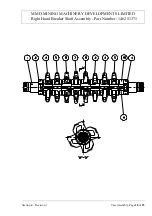
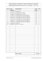
Страница 48: ...146251952 Fixed Bearing Assembly 139 1 3 146251953 Floating Bearing Assembly 137 1 4 6251321 01 Spacer Non Drive End 10 1 5 6251359 01 End Cap 7 2 6 031320050 M20 x 50 Hex Set Screw 0 17 1 7 030524070 M24 x 70 Socket Cap Screw Grade 12 9 0 36 16 8 030420000 M20 Hex Nut 0 06 1 9 111701004 Gear Coupling Assembly See Page 25 1 TOTAL MASS 2 538 kg Right Hand Breaker Shaft Assembly Part Number 24625195...

Страница 49: ...MMD MINING MACHINERY DEVELOPMENTS LIMITED Case Assembly Page 18 of 25 Section 4 Revision 1 Right Hand Breaker Shaft Assembly Part Number 146251371 ...

Страница 50: ...132 06 4 Tooth Ring Heavy Duty 0 Degrees 156 2 5 5050133 06 4 Tooth Ring Heavy Duty 15 Degrees 156 2 6 5050134 06 4 Tooth Ring Heavy Duty 30 Degrees 156 1 7 5050135 06 4 Tooth Ring Heavy Duty 45 Degrees 156 1 8 5050136 06 4 Tooth Ring Heavy Duty 60 Degrees 156 1 9 5050137 06 4 Tooth Ring Heavy Duty 75 Degrees 156 1 10 6250206 01 Half Spacer 42 1 11 5090021 01 Key 56 x 32 x 1890 26 2 TOTAL MASS 2 2...

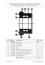
Страница 51: ...251428 01 Labyrinth Spacer 22 1 4 6251358 01 Spacer 7 1 5 6251850 01 Spacer 0 8 2 6 035000057 Spherical Roller Bearing 24044 CC C3 W33 30 5 1 7 030516050 M16 x 50 Socket Cap Screw Grade 12 9 0 11 16 8 030520050 M20 x 50 Socket Cap Screw Grade 12 9 0 18 12 9 032000220 Weston Oil Seal 250 x 280 x 16 R4 0 4 4 10 032000604 O Ring RM3193 57 0 1 1 TOTAL MASS 139 kg Fixed Bearing Assembly Part Number 146...

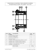
Страница 52: ...ate 15 1 3 6251428 01 Labyrinth Spacer 22 1 4 6251358 01 Spacer 7 1 5 035000057 Spherical Roller Bearing 24044 CC C3 W33 30 5 1 6 030516050 M16 x 50 Socket Cap Screw Grade 12 9 0 11 16 7 030520050 M20 x 50 Socket Cap Screw Grade 12 9 0 18 12 8 032000220 Weston Oil Seal 250 x 280 x 16 R4 0 4 4 9 032000604 O Ring RM3193 57 0 1 1 TOTAL MASS 137 kg Floating Bearing Assembly Part Number 146251953 ...

Страница 53: ...MMD MINING MACHINERY DEVELOPMENTS LIMITED Case Assembly Page 22 of 25 Section 4 Revision 1 HEAVY DUTY TOOTH CAP FIXINGS ASSEMBLY PART NUMBER 145060084 REVISION MODIFICATION DATE 1 0 FIRST ISSUE 14 12 00 ...

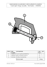
Страница 54: ...of 25 Section 4 Revision 1 Tooth Cap Fixings Assembly Part Number 145060084 ITEM PART NUMBER DESCRIPTION UNIT MASS QTY 1 5060084 84 Tooth Cap Material MMD 501 21 1 2 030536260 M36 x 260 Socket Capscrew 2 2 1 3 032736012 M36 Hex Nut 1xD Thick 0 4 1 TOTAL MASS 23 6 kg ...

Страница 55: ...MMD MINING MACHINERY DEVELOPMENTS LIMITED Case Assembly Page 24 of 25 Section 4 Revision 1 GEAR COUPLING ASSEMBLY PART NUMBER 1117010084 REVISION MODIFICATION DATE 1 0 FIRST ISSUE 14 12 00 ...

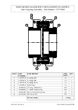
Страница 56: ...701005 01 Coupling Hub 28 1 2 1701006 01 Coupling Hub 17 6 1 3 1701007 01 Coupling Sleeve 22 1 4 1701008 91 Split Clamp 20 2 5 032000784 O Ring RM3493 57 0 01 2 6 036000002 BSPT Pressure Plug 0 01 2 7 030516090 M16 x 90 Socket Cap Screw 0 2 4 8 031416000 M16 Nyloc Nut 0 03 4 TOTAL MASS 109 kg Gear Coupling Assembly Part Number 111701004 ...

Страница 57: ...MINING MACHINERY DEVELOPMENTS LIMITED Fluid Coupling Assembly Page 1 of 3 Section 6 Revision 1 VOITH 487TVG FLUID COUPLING ASSEMBLY PART NUMBER 146251966 REVISION MODIFICATION DATE 1 0 FIRST ISSUE 14 12 00 ...

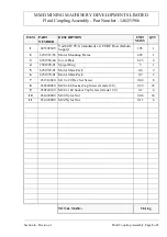
Страница 58: ...MMD MINING MACHINERY DEVELOPMENTS LIMITED Fluid Coupling Assembly Page 2 of 3 Section 6 Revision 1 Fluid Coupling Assembly Part Number 1416251966 ...

Страница 59: ...ting Frame 445 1 3 6251968 84 Cover Plate 8 25 2 4 1561828 01 Spigot Ring 3 1 5 6251969 01 Motor Shim Pack 0 6 2 6 6251970 01 Motor Shim Pack 0 7 2 7 031312020 M12 x 20 Hex Set Screw 0 04 8 8 030520080 M20 x 80 Socket Cap Screw Grade 12 9 0 25 22 9 030524140 M24 x 140 Socket Cap Screw Grade 12 9 0 2 6 10 031420000 M20 Nyloc Nut 0 06 22 11 031424000 M24 Nyloc Nut 0 11 6 TOTAL MASS 581 kg Fluid Coup...

Страница 60: ...MMD MINING MACHINERY DEVELOPMENTS LIMITED Wheel Carriage Assembly Page 1 of 3 Section 7 Revision 1 WHEEL CARRIAGE ASSEMBLY PART NUMBER 145040240 REVISION MODIFICATION DATE 1 0 FIRST ISSUE 14 12 00 ...

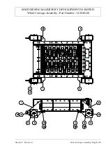
Страница 61: ...MMD MINING MACHINERY DEVELOPMENTS LIMITED Wheel Carriage Assembly Page 2 of 3 Section 7 Revision 1 Wheel Carriage Assembly Part Number 145040240 ...

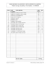
Страница 62: ...2 3 5040238 84 Trapping Bracket 30 4 4 5040239 85 Towing Eye 25 2 5 5040224 01 Wheel 120 4 6 5020060 01 Pin 15 4 4 7 5040068 01 Bronze Bush 1 3 8 8 031312040 M12 x 40 Hex Set Screw 0 05 8 9 030320320 M20 x 320 Hex Bolt 2 5 16 10 030324090 M24 x 90 Hex Bolt 0 41 16 11 030324100 M24 x 100 Hex Bolt 0 44 8 12 031420000 M20 Nyloc Nut 0 06 16 13 031424000 M24 Nyloc Nut 0 11 24 14 036000604 1 4 BSP Greas...

Страница 63: ... MINING MACHINERY DEVELOPMENTS LIMITED Centralised Greasing Assembly Page 1 of 2 Section 8 Revision 1 CENTRALISED GREASING ASSEMBLY PART NUMBER 146251983 REVISION MODIFICATION DATE 1 0 FIRST ISSUE 14 12 00 ...

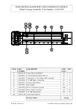
Страница 64: ... Joint Bracket 0 6 1 2 023060210 4 Way Distribution Block ZP A 0 5 1 3 023307507 10mm O D x 1 5mm Wall x 6MT Long Pipe 1 3 3 4 023307509 1 4 BSP Male 10mm Pipe 0 1 32 5 023307510 10mm x 10mm Elbow 0 1 12 6 023307511 Pipe Clamps 0 1 8 7 030512030 M12 x 30 Socket Cap Screw 0 04 2 8 031310020 M10 x 20 Hex Set Screw 0 2 10 9 032000451 1 4 BSP Bonded Seal 0 01 32 10 3991616 84 Grease Pipe Protector 5 2...

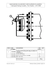
Страница 65: ...CHINERY DEVELOPMENTS LIMITED Underspeed Sensing Assembly Page 1 of 7 Section 9 Revision 1 CARLO GAVAZZI 110 VOLT UNDERSPEED SENSING ASSEMBLY PART NUMBER 143210000 REVISION MODIFICATION DATE 1 0 FIRST ISSUE 14 12 00 ...

Страница 66: ...1 Underspeed Sensing Assembly Part Number 143210000 ITEM PART NUMBER DESCRIPTION UNIT MASS QTY 1 143210000 Carlo Gavazzi Underspeed Sensing Assembly 110 Volt D C Comprising of 023210001 Sensor Ref DJ10G 0 35 1 023210002 Relay Ref S114156115 100 RPM 0 2 1 023210004 Base Ref S411 0 06 1 TOTAL MASS 0 6 kg ...

Страница 67: ...ation of this relay includes two selectable modes of operation and four selectable time ranges SECTION 1 BASIC OPERATION This section covers basics connections and settings of DIP switches for the modes of operation and time delay settings SECTION II MOMENTARY START CIRCUIT OPERATION This section covers the electric operation of the relay for a momentary start circuit and the required DIP switch s...

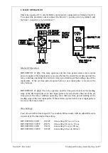
Страница 68: ...eriod expires before a new input pulse is received the relay releases DIP SWITCH 1 OFF The relay operates and the time period starts at the leading edge of the first input pulse If a new input pulse is received before the end of the set time period the relay continues operating for a full new time period starting at the leading edge of the new input pulse If the set time expires before a new input...

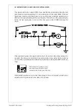
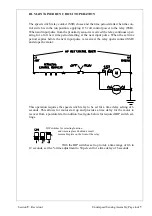
Страница 69: ... period expires before the next input pulse is received the relay opens contact SSR and stops the motor This operation requires the speed switch relay to be set for a time delay setting of 6 seconds This allows for motor start up and provides a time delay for the motor to recover from a potential stall condition See figure below for required DIP switch set tings DIP switches for selecting function...

Страница 70: ...set time period expires before the next input pulse is received the relay opens contact SSR and stops the motor This operation requires the speed switch relay to be set for a time delay setting of 6 seconds This allows for motor start up and provides a time delay for the motor to recover from a potential stall condition See figure below for required DIP switch set tings DIP switches for selecting ...

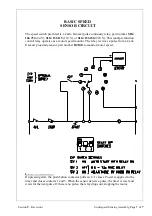
Страница 71: ... function control relay operates as a motor speed monitor The relay receives a pulse from a Carlo Gavazzi proximity sensor part number DJ10G to monitor motor speed BASIC OPERATION On pressing start the push button contactor pulls in C 1 closes Power is applied to the timer and closes contacts 1 and 3 When the sensor detects a pulse the timer is reset and waits for the next pulse If there is no pul...

Отзывы: