3 - 1
3. SIGNALS AND WIRING
3 SIGNALS AND WIRING
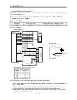
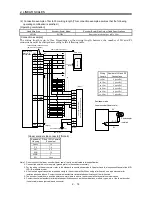
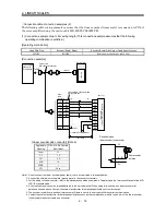
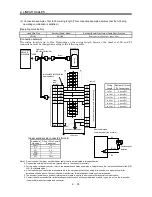
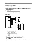
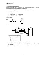
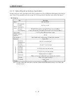
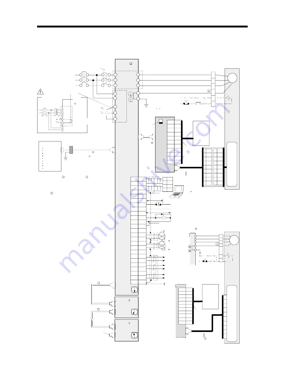
3.1 Standard connection examples of full closed control servo amplifier control signals
(1) When MR-J2S-CLP01 is used
24VDC
Note
1. Use the MR-J2HBUS M-A or MR-J2HBUS M cable within the overall
length of 30m. To improve noise immunity, it is recommended to use a
cable clamp and data line filters (connect 3 or 4 pcs. in series) near the
connector lead-out area.
2. The motor side connections of the second axis and later are omitted.
3. Up to eight axes (n = 0 to 7) can be connected.
The MR-H BN type servo can also be connected to the same bus.
(Note that the cable differs.)
4. In this example, the motor is equipped with an electromagnetic brake.
The power supply connected to the electromagnetic brake is irrelevant
to the polarity. The HC-SFS121 to 301, 202 to 702, 203, 353 and
HC-UFS202 to 502 use different connectors.
5. Connect the shield wire to the plate (ground plate) in the connector
securely.
6. Connect the diode in the correct orientation. If it is connected oppositely,
the amplifier will fail and signals will not be output.
7. A forced stop of the corresponding axis servo amplifier alone.
Use it as necessary when the QD75M, Q172, Q173 or Position Board is
connected. Do not use it when any of the A171SH, A172SH, A173UH
and A273UH is connected.
When this signal is not used, short EM1-SG within the connector.
Make an emergency stop of the whole system on the controller side.
A forced stop input can be made invalid using parameter No. 23.
8. For details, refer to the "MR-J2S-B Instruction Manual" and
"MR-J2S-CLP01 Installation Guide".
9. Always use a shielded multi-core cable. Up to 15m is allowed in noise-
free environment. However, the cable length should be within 3m when
38,400bps or more baud rate is set for RS-232C communication.
10. When using an external power supply, do not connect VDD-COM.
11. When the personal computer is connected simultaneously with analog
monitor output 1 (MO1) or analog monitor output 2 (MO2), use the
maintenance relay card (MR-J2CN3TM).
12. CN1A, CN1B, CN2 and CN3 have the same shape. Incorrect
connection of the connector can cause a failure.
13. In the case of single-phase 100VAC (MR-J2S-40B1-PY096 or less) or
single-phase 230VAC (MR-J2S-70B-PY096 or less), connect the
power supply to the L
1
, L
2
terminals and keep L
3
open.
G
H
7
6
8
9
5
4
14
2
3
LZ
LZR
LAL
LALR
SD
LBR
LB
P5L
LAR
LA
CN1 A
CLOSE
CN
1B
1
LG
7
8
1
2
4
5
9
P5
LG
MR
MRR
MD
MDR
SD
3 BAT
6 CNT
B1
B2
Z
S
R
C
D
A
B
F
G
N
M
24VDC
A
B
C
D
EM1
L1
L2
L3
C
P
N
TE1
L11
L21
B1
B2
5
6
Z
RA1
1
2
3
4
L
11
L
21
L
1
L
2
L
3
TE1
TE2
P
C
D
CN3
12
2
1
11
Rx
LG
LG
Tx
RD
SD
GND
GND
RS-232C
CS1
0
MO1
LG
MO2
LG
4
1
14
11
EMG
20
EM1
3
SG
RA1
13
MBR
5
COM
10
VDD
SD
LA
6
16
LAR
7
LB
LBR
17
LZ
8
LZR
18
CS1
1
8
1
2
4
5
9
P5
LG
MR
MRR
MD
MDR
SD
3 BAT
6 CNT
7
6
8
9
5
4
14
2
3
LZ
LZR
LAL
LALR
SD
LBR
LB
P5L
LAR
LA
CN1 A
1
LG
MR-J2S-CLP01
7
RA1
CN
1B
CS1
Configure a sequence that will turn off
MC at an alarm or emergency stop.
MC
NFB
Power supply
Three-phase 200 to
230VAC or single-phase
100VAC/single-phase
230VAC (Note 13)
If the regenerative option is
connected incorrectly, the servo
amplifier is damaged.
In the case of MR-J2S-500B/700B
Configure a sequence that will
turn off MC at an alarm or
emergency stop.
Servo amplifier
MR-J2S- B-S096
Regenerative
option
When connecting an external
regenerative option, always
disconnect the link from across C-P.
Regenerative
option
When connecting an external
regenerative option, always
disconnect the link from
across P-D.
Controller
A171SH
A172SH
A173UH
A273UH
QD75M
Q172
Q173
Position Board
Cable
clamp
Use the MR-J2HBUS M-A cable with the
A171SH,A172SH, A173UH or A273UH, and
the MR-J2HBUS M cable with the QD75M.
(Note 1)
Refer to the "Motion Controller Q Series Catalog"
for the cable between Q172/Q173 and amplifier,
and to the "Position Board, Interface Board New
Product News (SV0206-1)" for the cable between
Position Board and amplifier.
MR-J2HBUS M cable
MR-J2HBUS M cable
Always insert the terminating
connector (MR-A-TM) to the
termination of the servo bus.
Servo amplifier
MR-J2S- B
-PY096/-S096
(Axis 1)
(Note 12)
CN2
CN1A
(Note 12)
Plate
CN1B
(Note 12)
Servo amplifier
MR-J2S- B
(-PY096/-S096)
(Axis 2)
CN1A
(Note 12)
CN1B
(Note 2)
(Note 2)
CN1A
(Note 12)
CN1B
Servo amplifier
MR-J2S- B
(-PY096/-S096)
(Axis n)
Set SW1 to
CLOSE.
(Note 3)
CN2
(Note 12)
MR-J2HBUS M
cable
Use 1m or less.
A B Z-phase differential
input interface unit
MR-J2S-CLP01
Plate
(Note 12)
(Note 12)
Shut off when servo-on
signal turns off or alarm
signal turns on.
Motor
HC-KFS, MFS,
UFS3000r/min series
(Note 4)
SM
Electromagnetic
brake
E
nc
oder
General-purpose
linear scale or
rotary encoder
(A B Z-phase
differential output
type)
Connect the MR-HP4CN1
connector to the CN1A
connector.
(Note 8)
MR-JCCBL M-H cable or
MR-JCCBL M-L cable
Use 30m or less.
15m or less
(Note 9)
Commercially available
personal computer
Windows
(Note 7)
Forced stop
10m or less
(Note 6)
Electromagnetic
brake interlock
(Note 10) When not using the external power supply,
always connect VDD-COM.
Max. +1mA meter
Zero-center ( 10V output)
A
A
Monitor output 1
(Note 11)
Monitor output 2
10k
10k
Encoder A-phase pulse
(Differential line driver)
Encoder B-phase pulse
(Differential line driver)
Encoder Z-phase pulse
(Differential line driver)
2m or less
Plate
(Note 12)
Shut off when servo-on
signal turns off or alarm
signal turns on.
Motor
HC-SFS, RFS,
UFS2000r/min series
SM
(Note 4)
Electromagnetic
brake
E
nc
oder
General-purpose
linear scale or
rotary encoder
(A/B/Z-phase
differential output
type)
Connect the MR-HP4CN1
connector to the CN1A
connector.
MR-JHSCBL M-H cable,
MR-JHSCBL M -L cable
or MR-ENCBL M-H cable
Use 30m or less.
(Note 8)
U
V
W
A
EM1
n - 1
U
V
W
U
V
W
MR-J2S- B
-PY096/-S096
NFB
MC
U
V
W
D
D
Содержание Melservo-J2-SUPER series
Страница 19: ...1 6 1 FUNCTIONS AND CONFIGURATION MEMO...
Страница 49: ...2 30 2 LINEAR SCALES MEMO...
Страница 85: ...5 8 5 PARAMETERS MEMO...
Страница 89: ...7 2 7 OPTIONS AND AUXILIARY EQUIPMENT MEMO...

