2 - 16
2. LINEAR SCALES
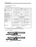
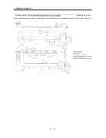
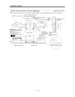
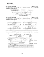
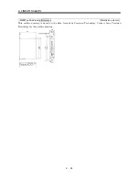
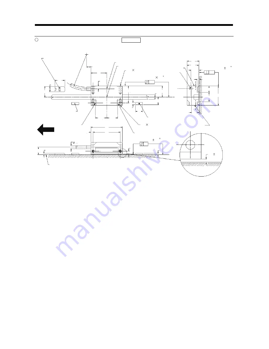
RGH26P, RGH26Q, RGH26R outline drawing Reference
(Dimension unit: mm)
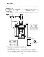
This outline drawing is based on the data from Renishaw. Contact Renishaw for this outline drawing.
Reference mark actuator
Dynamic bending radius R50
Static bending radius R10
6 minimum
Reference mark sensor position
Optical center
M3 0.5, two 9.5 deep holes
14
(Yaw tolerance 0.5 )
0.38
Mounting
surface
Setup
LED
(Roll tolerance 1.0 )
0.13
Mounting surface
range
Selectable mounting
surface
Q limit sensor position
M3 0.5, two 7.5
deep holes
Mount the Q
limit switch with
the white point up.
P limit sensor position
P limit switch
Mount it with the white point
directed toward the machine
stock side.
(Size is the same as that of
the Q limit switch.)
The arrow indicates the
forward moving direction
of the read head relative
to the scale.
Scale mounting surface
Clearance detail
(Pitch tolerance 1.0 )
0.8
0.8 0.1
7.6
27
13
9
3
11.6
16
17
15.5
6
10.5
10
3
23.5
14.6
14.6
44
38
10.6
5
2.2
4.7
7
14.5
22
4
2
3
Содержание Melservo-J2-SUPER series
Страница 19: ...1 6 1 FUNCTIONS AND CONFIGURATION MEMO...
Страница 49: ...2 30 2 LINEAR SCALES MEMO...
Страница 85: ...5 8 5 PARAMETERS MEMO...
Страница 89: ...7 2 7 OPTIONS AND AUXILIARY EQUIPMENT MEMO...

