4 - 20
4. OPERATION AND FUNCTIONS
4.6 About the MR Configurator
4.6.1 When current version of MR Configurator (MRZJW3-SETUP121 to -SETUP151 S/W: E0 version) is
used
The following indicates how to check whether the full closed-related parameter settings are normal or not
and whether the servo motor and full closed encoders operate normally or not.
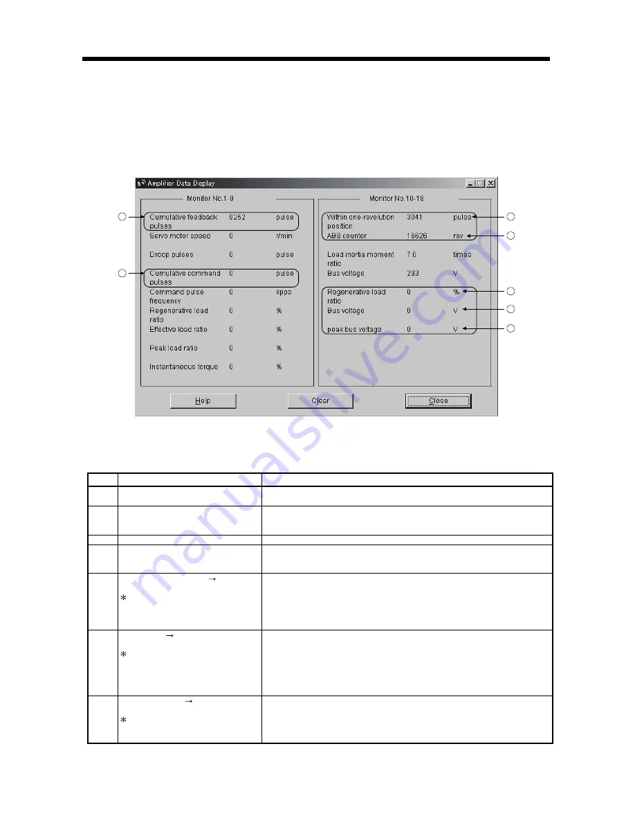
Select "MR-J2S-B" in the system setting of the MR Configurator. Opening the batch monitor screen
displays the following screen.
2
7
4
3
5
6
1
(1) Explanation of display items
The following table indicates the display items that are related to the servo motor and full closed
encoders.
Symbol
Name
Explanation
1)
Cumulative feedback pulse
Feedback pulses from the servo motor encoder are counted and displayed.
Click "Clear" to reset the value to 0.
2)
Command pulse frequency
Position command inputs from the command controller are counted and
displayed.
Click "Clear" to reset the value to 0.
3)
Within-one-revolution position
The within-one-revolution position of the servo motor encoder is displayed.
4)
ABS counter
The multi-revolution counter (number of revolutions from home position) of the
servo motor encoder is displayed.
The value is incremented or decremented by 1 per servo motor revolution.
5)
Regenerative load ratio ( read as
Cumulative feedback pulse 2
)
Caution: The name does not match
what is monitored. The real
regenerative load ratio is displayed on
the left side.
Feedback pulses from the full closed encoder are counted and displayed.
The value is displayed in the pulse unit of the closed encoder.
Click "Clear" to reset the value to 0.
6)
Bus voltage ( read as
Within-full-one-
revolution position
)
Caution: The name does not
match
what is
monitored
. The real bus
v
oltage is displayed two
lines
above.
The within-one-revolution position of the full closed encoder is displayed.
In the case of an INC linear scale, the Z-phase counter is displayed. The value
is counted up from 0 relative to the home position (reference mark). The value
is displayed in the pulse unit of the closed encoder.
In the case of an ABS linear scale, the virtual within-one-revolution position
(equivalent to lower 17 bits of the conversion result of 32-bit absolute position
data into the motor end unit, 0 to 131071) is displayed.
7)
Peak bus voltage ( read as
Full ABS
counter
)
Caution: The name does not match
what is monitored.
The multi-revolution counter (number of revolutions from home position) of the
full closed encoder is displayed.
In the case of an ABS linear scale, the virtual multi-revolution counter
(equivalent to lower 15 bits of the conversion result of 32-bit absolute position
data into the motor end unit, 0 to 32767) is displayed.
Содержание Melservo-J2-SUPER series
Страница 19: ...1 6 1 FUNCTIONS AND CONFIGURATION MEMO...
Страница 49: ...2 30 2 LINEAR SCALES MEMO...
Страница 85: ...5 8 5 PARAMETERS MEMO...
Страница 89: ...7 2 7 OPTIONS AND AUXILIARY EQUIPMENT MEMO...


