background image

iii

FX-10GM POSITIONING CONTROLLER

Guidelines for the safety of the user and protection of the FX-10GM unit
This manual provides information for the use of the FX-10GM unit. The manual has
been written to be used by trained and competent personnel. The definition of such a
person or persons is as follows;

a)

Any engineer who is responsible for the planning, design and construction of
automatic equipment using the product associated with this manual should be of
a competent nature,trained and qualified to the local and national standards
required to fulfill that role. These engineers should be fully aware of all aspects
of safety with regards to automated equipment.

b)

Any commissioning or service engineer must be of a competent nature,trained
and qualified to the local and national standards required to fulfill that job. These
engineers should also be trained in the use and maintenance of the completed
product. This includes being completely familiar with all associated documentation
for the said product. All maintenance should be carried out in accordance with
established safety practices.

c)

All operators of the completed equipment should be trained to use that product in
a safe and co-ordinated manner in compliance to established safety practices.
The operators should also be familiar with documentation which is connected
with the actual operation of the completed equipment.

Note: the term 'completed equipment' refers to a third party constructed device which
contains or uses the product associated with this manual.

Notes on the symbology used in this manual

At various times through out this manual certain symbols will be used to highlight
points of information which are intended to ensure the users personal safety and protect
the integrity of equipment. Whenever any of the following symbols are encountered its
associated note must be read and understood. Each of the symbols used will now be
listed with a brief description of its meaning.

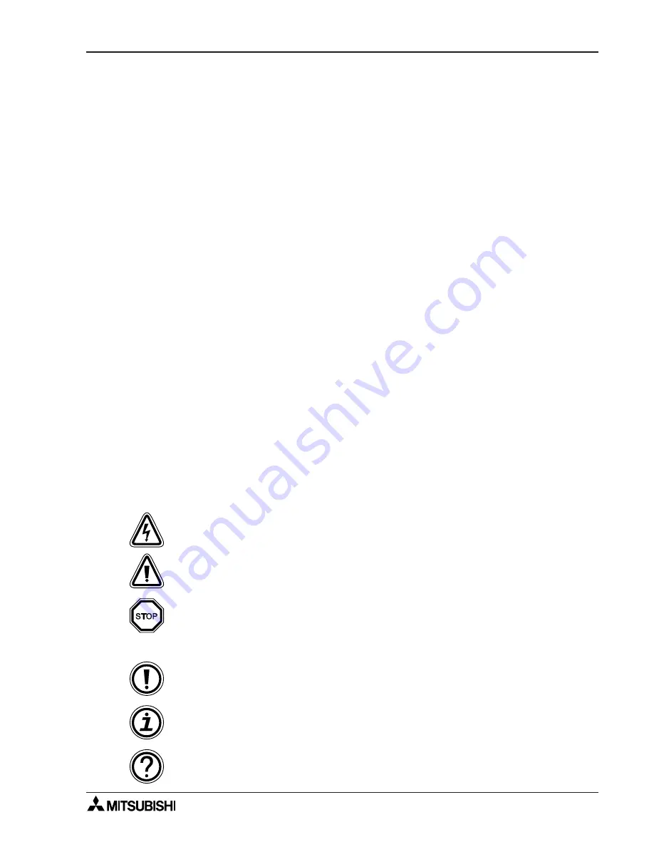
Software warning

Indicates a point of interest or further explanation

Indicates a  special point which the user of the associate software element
should be aware of

Indicates special care must be taken when using this element of software

Hardware warnings

Indicates that the identified danger could POSSIBLY cause physical and
property damage.

Indicates that the identified danger WILL cause physical and property
damage.

Indicates a point of further interest or further explanation.

Содержание FX-10GM

Страница 1: ...RAMMING MANUAL and FX SERIES HARDWARE MANUAL Before attempting to install or use the FX 10GM unit this manual and FX 10GM FX E 20GM HARDWARE PROGRAMMING MANUAL should be read and understood If in doub...

Страница 2: ...FX 10GM POSITIONING CONTROLLER ii...

Страница 3: ...e completed equipment should be trained to use that product in a safe and co ordinated manner in compliance to established safety practices The operators should also be familiar with documentation whi...

Страница 4: ...iguration 1 3 1 3 External Dimensions 1 4 2 SPECIFICATIONS 2 1 2 1 General Specifications 2 1 2 2 Power Supply Specifications 2 1 2 2 1 Power Supply Specifications 2 1 2 2 2 Service power supply 2 2 2...

Страница 5: ...o motor via the drive unit Number of control axes Positioning languages Number of output pulses Connection to Programmable controller 1 Dedicated language Sequence language 1 to 200 kPPS Connected to...

Страница 6: ...nit block for the programmable controller Mounting hole 2 5 5 DIN rail Not used when the unit is mounted to a DIN rail Operation indicator LEDs I O output status indicator LEDs 2C MANU COM1 1 2 System...

Страница 7: ...Y7 COM3 Y11 Y13 COM4 Y15 Y17 PULL 24 24 COM1 MANU B POWER 3 7 0 4 1 5 2 6 3 7 0 4 1 5 2 6 A POWER 3 7 0 4 1 5 2 6 3 7 0 4 1 5 2 6 TRANSISTOR BLOCK A B 24 24 COM1 MANU 1 0 1 2 3 COM COM 4 5 6 7 COM COM...

Страница 8: ...5 6 Various data settings can be fetched through connections that save wiring either by a direct connection method or by multiplexing input outputs General output extension output 1 Auxiliary equipme...

Страница 9: ...d Stop command Zero return command 2 Mechanical system inputs Forward rotation limit Reverse rotation limit Near point dog signal Manual forward rotation command Manual reverse rotation command Manual...

Страница 10: ...ZRN STOP Y5 X0 X1 X2 X3 Y0 Y1 Y2 Y3 Y4 CLR MANU SVRDY SVEND PGO FP RP CPU E POWER READY ERROR 140 125 Width 35mm DIN rail moun ting groove 10 40 50 95 2 5 5 Mounting hole 1 3 External Dimensions Weig...

Страница 11: ...not allowed 2 Ambient atmosphere Free from corrosive gas and excessive dust 1 0 5G when mounted to a DIN rail 2 2 SPECIFICATIONS For complefe operation wiring mounting and programming instructions ple...

Страница 12: ...ormance Specifications Item Specifications Number of control axes 1 Applicable programmable controller Bus connection with FX FX2C Series PC Number of I O points occuupied 8 points Program memory 3 8k...

Страница 13: ...with instruction cods 13 types Sequence 11 types LD LDI AND ANI OR ORI ANB ORB SET RST NOP Application FNC No system 29 types M codes maintask m00 WAIT program stop and m02 END m01 m03 to m99 can be...

Страница 14: ...r less 0 3 mA or less PG0 0 5 mA or less Signal format Contact input or NPN open collector transistor input Response time Group 1 Approx 0 5 msec Approx 3 msec Group 2 Approx 3 msec Approx 3 sec Group...

Страница 15: ...utput is ON LED is lit while output is ON External power supply 5 to 24V DC 10 5 to 24V DC 10 Load current 20 mA or less 50 mA or less Open circuit leak current 0 1 mA 24V DC or less 0 1 mA 24V DC or...

Страница 16: ...connector cables made by the user and for the connectors to be used when connecting additional equipment are indicated below 1 When making a cable Flat cables Wire size AWG28 0 1 mm2 1 27 pitch 20 co...

Отзывы: