background image

INTRODUCTION   1

1-4

FX-10GM POSITIONING CONTROLLER

Units for general I/O connection
For the general I/Os of the positioning unit and the extension I/Os of the programmable
controller the following external units can be connected.

1)

Various input switches
The various input switches such as a push-button switch, limit switch, sensor,
etc. can be connected.

2)

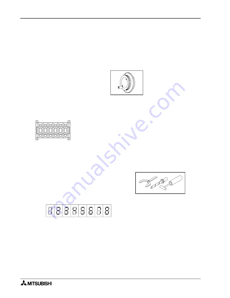
Manual pulse generator
A   p u l s e   g e n e r a t o r   c a n   b e
connected to each axis, or one
p u l s e   g e n e r a t o r   c a n   b e
connected to both axes and
switched between them.  The
manual pulse generators used
must be an open collector output
type.

General input/extension input
1)

Input from the digital switch

3)

Interrupt input
T h e   i n p u t   f r o m   t h e
manual pulse generator
can be used as control
i n p u t   f o r   i n t e r r u p t
positioning control by
switching the line.

90

0

10

60

70

80

• Up to 6 digits are

possible with the FX-
10GM. Use with a
programmable cont-
roller for more digits.

1 2 3 4 5 6

+

-

+

-

+

-

+

-

+

-

+

-

Various data settings can be fetched
through connections that save wiring,
either by a direct connection method
or by multiplexing input/outputs.

General output/extension output
1)

Auxiliary equipment control output
The ON/OFF control outputs for
various auxiliary equipment are
generated by M code signals (2-digit
BCD) or a direct program.

2)

Seven-segment display

Various setting data and statuses,
and present value, can be displayed
through connections that save wiring,
either by a direct connection method
or by multiplexing outputs.

The following data can be set using
direct specification instructions.

• Target position

• Speed

• Center coordinates of circular arc
• Radius of circular arc
• Various parameters and control constants

a) Current position display:

8 digits maximum for each axis.

b) The line No. being executed, the set

speed, the present dwell value, various
parameters and the status can be read
and displayed.

• Up to 2 digits are possible with the

FX-10GM.  Use with a programmable
controller for more digits.

The positioning control command inputs and the drive unit connection are enabled
via dedicated I/O.

Содержание FX-10GM

Страница 1: ...RAMMING MANUAL and FX SERIES HARDWARE MANUAL Before attempting to install or use the FX 10GM unit this manual and FX 10GM FX E 20GM HARDWARE PROGRAMMING MANUAL should be read and understood If in doub...

Страница 2: ...FX 10GM POSITIONING CONTROLLER ii...

Страница 3: ...e completed equipment should be trained to use that product in a safe and co ordinated manner in compliance to established safety practices The operators should also be familiar with documentation whi...

Страница 4: ...iguration 1 3 1 3 External Dimensions 1 4 2 SPECIFICATIONS 2 1 2 1 General Specifications 2 1 2 2 Power Supply Specifications 2 1 2 2 1 Power Supply Specifications 2 1 2 2 2 Service power supply 2 2 2...

Страница 5: ...o motor via the drive unit Number of control axes Positioning languages Number of output pulses Connection to Programmable controller 1 Dedicated language Sequence language 1 to 200 kPPS Connected to...

Страница 6: ...nit block for the programmable controller Mounting hole 2 5 5 DIN rail Not used when the unit is mounted to a DIN rail Operation indicator LEDs I O output status indicator LEDs 2C MANU COM1 1 2 System...

Страница 7: ...Y7 COM3 Y11 Y13 COM4 Y15 Y17 PULL 24 24 COM1 MANU B POWER 3 7 0 4 1 5 2 6 3 7 0 4 1 5 2 6 A POWER 3 7 0 4 1 5 2 6 3 7 0 4 1 5 2 6 TRANSISTOR BLOCK A B 24 24 COM1 MANU 1 0 1 2 3 COM COM 4 5 6 7 COM COM...

Страница 8: ...5 6 Various data settings can be fetched through connections that save wiring either by a direct connection method or by multiplexing input outputs General output extension output 1 Auxiliary equipme...

Страница 9: ...d Stop command Zero return command 2 Mechanical system inputs Forward rotation limit Reverse rotation limit Near point dog signal Manual forward rotation command Manual reverse rotation command Manual...

Страница 10: ...ZRN STOP Y5 X0 X1 X2 X3 Y0 Y1 Y2 Y3 Y4 CLR MANU SVRDY SVEND PGO FP RP CPU E POWER READY ERROR 140 125 Width 35mm DIN rail moun ting groove 10 40 50 95 2 5 5 Mounting hole 1 3 External Dimensions Weig...

Страница 11: ...not allowed 2 Ambient atmosphere Free from corrosive gas and excessive dust 1 0 5G when mounted to a DIN rail 2 2 SPECIFICATIONS For complefe operation wiring mounting and programming instructions ple...

Страница 12: ...ormance Specifications Item Specifications Number of control axes 1 Applicable programmable controller Bus connection with FX FX2C Series PC Number of I O points occuupied 8 points Program memory 3 8k...

Страница 13: ...with instruction cods 13 types Sequence 11 types LD LDI AND ANI OR ORI ANB ORB SET RST NOP Application FNC No system 29 types M codes maintask m00 WAIT program stop and m02 END m01 m03 to m99 can be...

Страница 14: ...r less 0 3 mA or less PG0 0 5 mA or less Signal format Contact input or NPN open collector transistor input Response time Group 1 Approx 0 5 msec Approx 3 msec Group 2 Approx 3 msec Approx 3 sec Group...

Страница 15: ...utput is ON LED is lit while output is ON External power supply 5 to 24V DC 10 5 to 24V DC 10 Load current 20 mA or less 50 mA or less Open circuit leak current 0 1 mA 24V DC or less 0 1 mA 24V DC or...

Страница 16: ...connector cables made by the user and for the connectors to be used when connecting additional equipment are indicated below 1 When making a cable Flat cables Wire size AWG28 0 1 mm2 1 27 pitch 20 co...

Отзывы: