background image

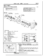
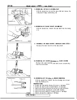
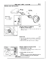
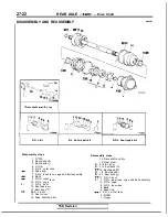
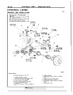
REAR AXLE 

   Drive Shaft

27-25

Snap

inner 

1180116

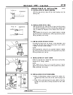
(4) Secure the 

 boot with boot bands (A) and 

 to the

drive shaft and B.J.

Caution
Ensure that the 

 is at a zero angle with the drive

shaft to ensure the boot contains the specified
amount of air.

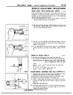
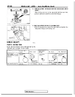
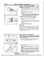
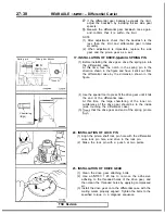
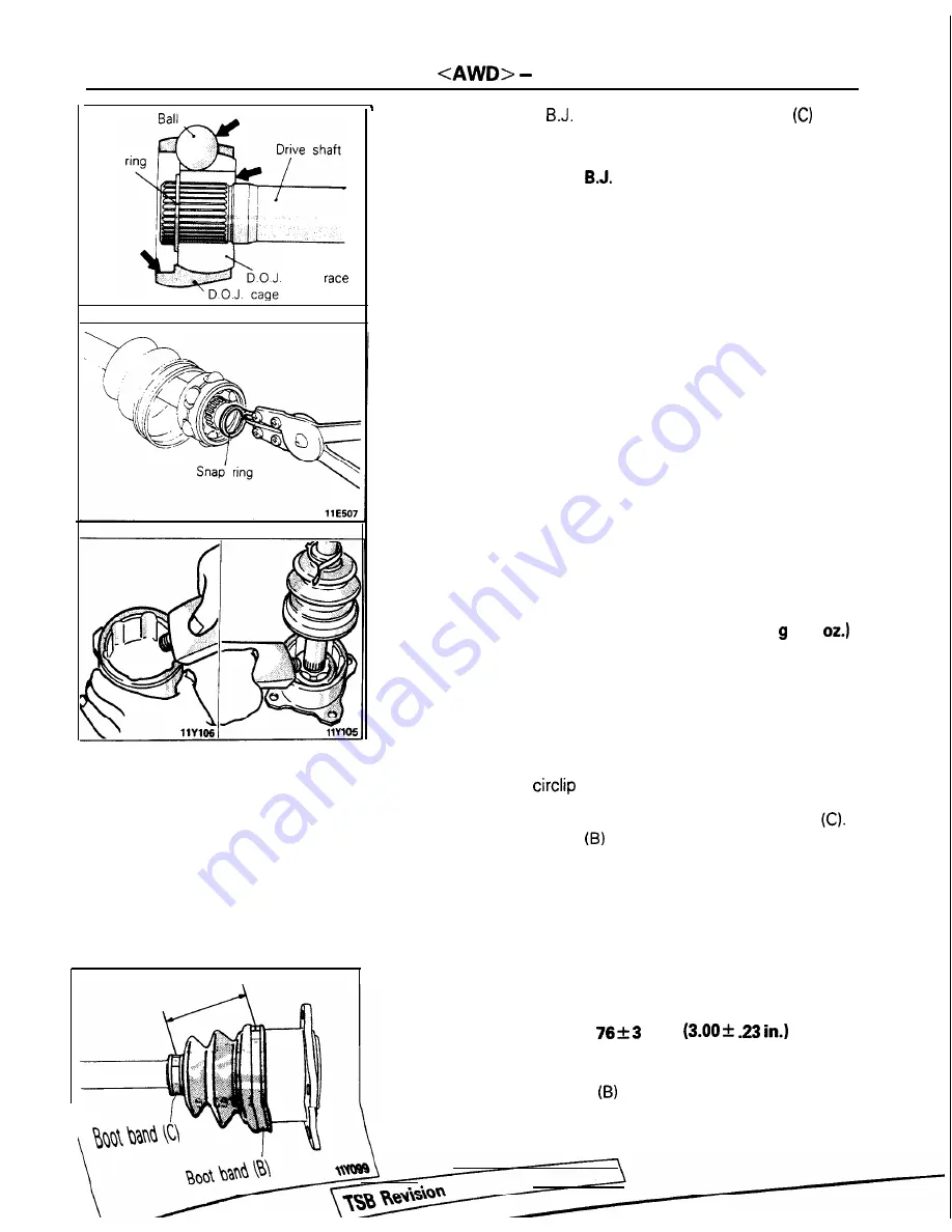
7. INSTALLATION OF D.O.J. INNER RACE, CAGE AND

BALL ASSEMBLY

(1) Apply the specified grease to the D.O.J. cage, the balls

and the D.O.J. inner race.

Specified grease: Repair kit grease (As required)

(2) Install the cage, balls and inner race to the drive shaft,

then, using snap ring pliers, fit the snap ring securely
into the groove in the shaft.

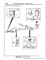
5. APPLICATION OF GREASE TO D.O.J. OUTER RACE

(1) Fill the specified grease to the D.O.J. outer race, fit the

drive shaft into the D.O.J. outer race, and then fill more
grease to the D.O.J. outer race.

Specified grease: Repair kit grease

90   (3.2 

Caution
The grease in the repair kit should be divided in half

for use, respectively, at the joint 

and 

inside the

boot.
A special type of grease is used on the joint. Be
cautious to ensure that no other grease is allowed

to come in contact with the joint.

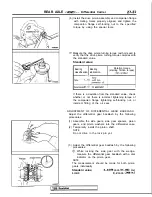
(2) Install the 

 to the D.O.J. outer race.

(3) Assemble the D.O.J. boot to the D.O.J. outer race, then

secure the boot to the drive shaft with boot band 

(4) Place boot band 

 on the D.O.J. boot.

NOTE
Do not secure boot band (B).

(5) Set the D.O.J. boot bands at the specified distance in

order to adjust the amount of air inside the D.O.J. boot,
and then tighten the D.O.J. boot band (C) securely.

Standard value: 

 mm 


(6) Release a part of the D.O.J. boot from the D.O.J. outer

race to allow pressure to escape from the boot.

(7) Tighten 

boot band 

 and secure the D.O.J. boot.

Содержание 1989 Galant

Страница 1: ...E TXT or README HTML for additional information 1 kyou Gjmpiemym_ay h A WE SUPPORT VOLUNTARY TECHNICIAN CERTIFICATION THROUGH Nallonal lnsrltule for AU v3 VPCT VE EXCELLENCE naiLcorn MITSUBISHI MOTOR SALES OF AMERICA Inc Mltsublshl Motors Corporat on reserves the right to make changes in design or to make additions to or Improvements In Its products wlthout mposng any obllgatlons upon Itself to in...

Страница 2: ......

Страница 3: ...ant 44 Engine Oil 41 Engine Oil Filter 41 Exhaust System 45 Fuel Hoses 39 Fuel System 39 Manual Transaxle 42 Rear Axle 45 Rear Drum Brake Linings and Rear Wheel Cylinders 44 Spark Plugs 40 Timing Belt 40 MASTER TROUBLESHOOTING 28 PRECAUTIONS BEFORE SERVICE 15 RECOMMENDED LUBRICANTS AND LUBRICANT CAPACITIES TABLE 35 SCHEDULED MAINTENANCE TABLE 38 SPECIAL HANDLING INSTRUCTIONS FOR AWD MODELS 20 TABL...

Страница 4: ...00 z NOTES ...

Страница 5: ... or the value to which the part or assembly is corrected and adjusted It is given by tolerance LIMIT Shows the standard for judging the quality of a part or assembly on inspection and means the maximum or minimum value within which the part or assembly must be kept functionally or in strength It is a value established outside the range of standard value REFERENCE VALUE Indicates the adjustment val...

Страница 6: ...eassembly steps Specified in case reassembly is im possible in reverse order of disassem bly steps Omitted if reassembly is possible in reverse order of disassembly steps Classifications of Major Maintenance Service Points When there are major points relative to mainte nance and servicing procedures such as essential maintenance and service points maintenance and service standard values informatio...

Страница 7: ...ng procedures cautions I I iY W1 1 etc on removal installation dis se an 3rM rr paNo 3W scribed 1 assembly and reassembly are de 37A 24 STEERING NINA Steering Gear Box SERVICE POINTS OF REMOVALJ ll37 kM 6 DlSCONNECllON OF TIEROD END Using the special tool disconnect the tie rod from the knuckle ceurion 1 Besretotiethewrdofthespeciaitodtomen P 2 Loosenthenutbutdonotremoveit 12 REMOVAL OF GEAR BOX A...

Страница 8: ...Provides the necessary de scription of cir curt operation for basic under s t a n d i n g N O 1 The passenger cPrrlpmme l lemperatu4 r tnput sigrml is hid to Z C 77 F N O 1 2 The ou sde ar sensor inpu srgnal IS held to WC 5IpF _ N O 13 The air t mpSf SenSO VlPut SlgMl 6 t 10 4 G33 F I Airwndtlimluconhdunittwmirutwtmge I 16 I lYle MI Passenger com wnme t tawa 1 sensor Parr lem mat r 25 c OFFI 7 to ...

Страница 9: ...ol is indicated by sym A V The A symbol indic that current flows in upward direction output The broken line indicates the t r same connector The connector symbol indicates the device side connector for an intermediate con nector the male side connectorj as seen from the terminal fronl t h e connectois rnnnection face RELAY devce side con I MOTOR Indicates that the con nector is the direct inser ti...

Страница 10: ...igh 5 Premium Engine Check digits Model year Make Vehicle type Others Plant Serial number Country Okazaki Plant D 2 0 dm3 122 cu in SOHC MFI E 2 0 dm3 122 cu in DOHC MFI K 1989 Year L 1990 Year M 1991 Year N 1992 Year P 1993 Year J Japan A Mitsu bishr 3 Passen 9er Car c Auto matic Seat Belt D Manual Seat Belt NOTE l Check digit means a single number or letter x used to verify the accuracy of trans...

Страница 11: ... DOHC MFI JA3CX56RnLZ Mitsubishi E38ASNGML2M Galant tAWD VEHICLES FOR CALIFORNIA V I N except sequence number Brand Engine Displacement Models Code JA3CR46VC LZ Mitsubishi 2 0 dm3 122 cuin E33ASNHEL7MlRHEL7M Galant FWD SOHC MFI JA3CR56VC LZ E33ASNXEL7MIRXEL7M JA3CR56RnLZ 2 0 dm3 122 cuin E33ASNGML7M DOHC MFI JA3CX56ROLZ Mitsubishi E38ASNGML7M Galant AWD I991 MODELS VEHICLES FOR FEDERAL V I N excep...

Страница 12: ...subishi 1 Galant FWD Mitsubishi Galant AWD Engine Displacement 2 0 dm3 122 cu in SOHC MFI 2 0 dm3 122 cu in DOHC MFI 2 0 dm3 122 cu in DOHC MFI Turbo 1 Models Code E33ASNHEL2MIRHEL2M E33ASRXEL2M E3gf2N ML2M AGML2M E38ASNGML2M RGML2M E39ASNPFL2M VEHICLES FOR CALIFORNIA V I N except sequence number I JA3CR56RnNZ j Mw wm 1 g gwo 1993 MODELS VEHICLES FOR FEDERAL 2 0 dm3 122 cu in DOHC MFI E33ASNGML7M ...

Страница 13: ...shows model code engine model transaxle model and body color code 1 MODEL 2 ENGINE 3 EXT 4 TRANSAXLE 5 COLOR INT OPT E33AS RGELZM LzI S y 4G63 Engine model CA6 IExterior co F5M22 L Transaxle model R82 87V 03V p cf l CHASSIS NUMBER MOOCE STAMPING LOCATION The chassis number is stamped on the top Center of the firewall located in the engine compartment CHASSIS NUMBER CODE CHART E33AKZOOOOl T T 1 Veh...

Страница 14: ...In order to protect against theft a Vehicle ldentificatlon Number VIN is stamped in or attached as a label to the following major parts of the engine and transaxle as well as main outer panels Engine cylinder block Transaxle housing Fender Door Quar ter panel Hood Trunk lid Bumpers In addition a theft protection label is attached to replacement parts for the body outer panel main components and th...

Страница 15: ...ification 00 13 LOCATIONS Part Engine ansaxle Target area for original equipment parts LZZB for replacement parts SOHC Up to 1992 models SOHC l 993 models DOHC Manual transaxle Automatic transaxle FWD AWD 17 1 TSB Revision ...

Страница 16: ...rts inner side of the parts shown OOA0065 The illustration indicates left hand side outer Right hand side is symmetrically opposite OOA0056 OOAOO59 inner side of the parts shown in the figure The illustration indicates left hand side outer TSB Revision ...

Страница 17: ...oceeding with work on the electrical system Note that the following must never be done Unauthorized modifications of any electrical device or wiring because such modifications might lead to a vehicle malfunction over capacity or short circuit that could result in a fire in the vehicle When servicing the electrical system disconnect the negative cable terminal from the battery TSB Revision ...

Страница 18: ...accessories OFF Transaxle neutral position A T models N or P Steering wheel neutral center position m m tn 1 Scan Tool Multi use tester MUT ROM pack 1 VEHICLE WASHING If high pressure car washing equipment or steam car washing equipment is used to wash the vehicle be sure to maintain the spray nozzle at a distance of at least 300 mm 12 in from any plastic parts and all opening parts doors luggage ...

Страница 19: ...s vehicle is towed use wheel lift or flat bed equipment Manual transaxle vehicles may be towed on the front wheels provided the transaxle is in neutral and the drive line has not been damaged The steering wheel must be clamped in the straight ahead position with a steering wheel clamping device designed for towing service use Caution Do not use steering column lock to secure front wheel position f...

Страница 20: ... hoist The hoist must be equipped with the proper adapters in order to support the vehicle at the proper locations Caution When service procedures require removing rear suspen sion fuel tank spare tire and lift gate place additional weight on rear end of vehicle or anchor vehicle to hoist to prevent tipping of center of gravity changes FLOOR JACK The usual type of floor jack is used at the followi...

Страница 21: ...pproximate center of gravity Frame contact hoist twin post hoist or scissors jack emergency locations EMERGENCY JACKING Jack receptacles are located at the body sills to accept the scissors jack supplied with the vehicle for emergency road service Always block opposite wheels and jack on level surface TSB Revision ...

Страница 22: ...be applied AK OOA0032 Front wheels lifted No good l The vehicle must not be towed by placing only its front wheels or only the rear wheels on a rolling dolly because to do so will result in deterioration of the viscous coupling and result in the viscous coupling causing the vehicle to jump forward suddenly OOA0034 Front wheels lifted No good l If only the front wheels or only the rear wheels are l...

Страница 23: ... and Gauges Caution Do not operate the clutch suddenly or increase or reduce speed suddenly during the work Front wheel side slip To prevent the front wheels from moving from side to side attach tension bars to the towing hooks and secure both ends at anchor plates Accident prevention procedures 1 Attach a chain or wire to the rear traction hook Make sure the end of the wire or chain is secured fi...

Страница 24: ...cing machlne OOA0046 Balancw Pick up stand 0010024 TSB Revision 2 Release the parking brake 3 Rotate each wheel manually and check to be sure that there is no dragging 3 Use the engine to drive the tires and then make the measurement Caution 1 If an error is indicated in the state of engine drive motor drive can be used concurrently 2 Do not operate the clutch suddenly or increase or reduce speed ...

Страница 25: ... 1 435 56 5 1 410 55 5 Wheel base 4 2 600 102 4 2 600 102 4 2 600 102 4 2 600 102 4 Tread Front 5 1 460 57 5 1 460 57 5 1 460 57 5 1 460 57 5 Rear 6 1 450 57 1 1 450 57 1 1 450 57 1 1 450 57 1 Overhang Front 7 980 38 6 980 38 6 980 38 6 980 38 6 Rear 8 1 090 42 9 1 090 42 9 1 090 42 9 1 090 42 9 Height at curb mass wt Front bumper to ground 9 240 9 4 250 9 8 255 10 0 255 10 0 Rear bumper to ground...

Страница 26: ...Manual transaxle F5M22 F5M3 1 W5M31 W5M33 Automatic transaxle F4A22 F4A22 W4A32 Clutch Type Dry single disc Dry single disc Dry single disc Dry single disc diaphragm diaphragm diaphragm diaphragm spring spring spring spring Chassis Tire 185 7OR14 87s 195 60R15 86i i 195 60R15 86ti 195 60R15 86H or 195 65R14 89H Front suspension Type Independent Independent Independent Independent strut strut strut...

Страница 27: ...mper to ground 10 215 8 5 290 11 4 Minimum running ground clearance 11 115 4 5 155 6 1 Angle of approach 12 18 5 19 Angle of departure 13 12 17 lehicle weight kg tbs Curb weights M T 1 230 2 712 or 1 250 2 755 I 31 0 2 888 A T 1 250 2 755 or 1 285 2 833 3 or 1 270 2 800 4 Gross vehicle weight rating 1 700 3 747 1 780 3 923 Gross axle weight rating Front 900 1 984 960 2 116 Rear 800 1 763 820 1 807...

Страница 28: ...85 3 35 mm in 88 3 46 cm3 win 1 9 9 7 122 8 5 1 3 4 2 TRANSAXLE SPECIFICATIONS Items Type Gear ratio 1 st 2nd 3rd 4th 5th Reverse Transaxle Pnmary reduction ratio Secondary reductron ratio Transfer F5M22 F5M3 1 5 speed M T W5M31 EFd 5 speed M T F4A2 2 4 speed A T 4 speed A T 3 363 2 846 2 846 2 846 1 947 1 833 1 684 1 684 1 285 1 217 1 115 1 115 0 939 0 888 0 833 0 833 0 756 0 73 1 0 690 0 666 3 0...

Страница 29: ...4 6 2 9 4 3 5 7 3 6 5 1 M6 1 o 4 6 2 9 4 3 7 1 1 5 1 8 0 8 1 2 5 8 8 7 M8 1 25 9 1 4 6 5 10 17 26 12 19 20 30 14 22 Ml0 1 25 19 28 14 20 35 55 25 40 45 60 33 43 Ml2 1 25 34 50 25 36 70 95 51 69 85 110 61 80 Ml4 1 5 60 85 43 61 120 160 87 116 130 180 94 130 Ml6 1 5 95 130 69 94 180 240 130 174 200 270 145 195 Ml8 1 5 140 190 101 137 260 350 188 253 300 400 217 289 Bolt nominal Pitch Torque Nm ft lb...

Страница 30: ...ts Probable cause Reference page Coolrng system faulty 14 5 Incorrect ignition timing 16 39 40 ENGINE WILL NOT CRANK OR CRANKS SLOWLY Symptom Probable cause Engine will not crank Starting system faulty or cranks slowly Reference page 16 14 ENGINE WILL NOT START OR HARD TO START CRANKS OK Symptom Probable cause Reference page Engrne WIII not start or hard to start Cranks OK No fuel supply to inject...

Страница 31: ...s Engine overheats Compression too low 13 8 119 205 17 22 14 5 11 6 ENGINE HESITATES OR POOR ACCELERATION Symptom Engine hesrtates or poor acceleration Probable cause Ignition system problem Vacuum leaks 0 Purge control valve hose l Vacuum hoses l Intake manifold l Intake manifold plenum l Throttle body l EGR valve Reference page 16 32 17 3 Air cleaner clogged Fuel line clogged Fuel injection syst...

Страница 32: ...ry 16 32 13 8 119 205 1 l 6 31 3 21 4 35 l 3 NOISE Symptom Noise Probable cause Loose bolts and nuts Engine noise Reference page or remedy Retighten as necessary Repair as necessary HARD STEERING Symptom Hard steering Probable cause Reference page or remedy Loose power steering oil pump belt 37A 21 Low fluid level Replenish Air in power steering system 37A 22 Low tire pressure 31 3 Excessive turni...

Страница 33: ...lmbalanced wheels Repair Improper front or rear wheel alignment 33A 5 34 5 11 23 35 Malfunctioning shock absorber Malfunctioning electronic control suspension 33B 90 system Broken or worn stabilizer 33A 6 13 17 34 l 1 35 37 Broken or worn coil spri ng Loose suspension secuiring bolt s Retighten Worn lower arm bushing 33A 10 Worn suspension arm bushing 33A IO TSB Revision ABNORMAL TIRE WEAR Symptom...

Страница 34: ...tires 31 3 Uneven tire pressure Excessive turning resistance of lower arm ball 33A 17 joint Wheel bearing seizure Replace Broken or weak coil spring 33A 7 Bent front axle drive shaft 26 13 Deformed lower arm 33A 10 STEERING WHEEL SHIMMY Symptom Steerlng wheel shlmmy Probable cause Improper front or rear wheel alignment Reference page or remedy 33A 5 34 5 23 Improper tire pressure I 31 3 lmbalanced...

Страница 35: ...ad of roiling along race surface rollers slide insufficient grease thus damaging surface Excessive bearing preload Excessive load Faulty oil seal Smearing Damage or wear caused by minute particles Excessive variation of loads on adhering to surfaces results in rolugh movement bearings and such high temperatures that parts of surface Use of grease other than that melt specified Insufficient grease ...

Страница 36: ...tion system defines oil perform ance in terms of engine usage Only engine oil designed For Service SG or For Service SGKD when available should be used These oils contain sufficient chemical additives to provide maximum engine protection Both the SAE grade and the API designation can be found on the container Caution Test results submitted to EPA have shown that laboratory animals develop skin can...

Страница 37: ...hol it IS recommended that the car be operated on gasoline Methanol Do not use gasolines containing methanol wood alcohol Use of this type of alcohol can result in vehicle performance deteriora tion and damage critical parts in the fuel system components Fuel system damage and performance problems resulting from the use of gasolines containing methanol may not be covered by the new car warranty Ga...

Страница 38: ...3 62 dm3 U S measure 3 7 qts 4 2 qts 4 2 qts 1 I2 qt 1 I2 qt 7 6 qts 5 4 qts 6 9 qts 95 qt 15 9 gals 16 4 gals Temperature range anticipated before next oil chanae SAE SW 30 SW 40 I Recommended viscosity SAE M03BOOl SELECTION OF LUBRICANTS ENGINE OIL Engine oil should be used which conform to the requirements of the API classification For Service SG or For Service SGKD and have the proper SAE grad...

Страница 39: ... 8OW SAE 8OW 90 Below 34 C 30 F SAE 75W SELECTION OF COOLANT COOLANT Relation between Antifreeze Concentration and Specific Gravity Safe operating Coolant temperature concentration C F Specific volume 11 12 2 30 20 t 4 _ j 35 2O 4 40 25 13 45 31 23 8 50 37 35 55 45 49 60 Example The safe operating temperature is 15 C 5 F when the measured specific gravity is 1 058 at the Coolant temperature of 20 ...

Страница 40: ...n Thousands 15 30 45 50 60 Timing Belt Including the Balancer Belt Replace at X Drive Belt for Water Pump Inspect for tension at X X and Generator Non Turbo Change Every Year Every 12 000 km Or 7 500 miles Turbo Change Every 6 Months Every 8 000 km Or 5 000 miles I I Non Turbo Change Every Year or X X X X Every 16 000 km Or 10 000 miles Engine Oil Filter Turbo Change Every Year Manual Transaxle Oi...

Страница 41: ...on in heavy city trafic during hot weather above 32 C 90 F MAINTENANCE SERVICE 1 FUEL SYSTEM Tank Lines Connections and Fuel Tank Filler Tube Cap Check for leaks 2 FUEL HOSES Check for leaks or damagekOOSnOB 1 Check for damage or leakage in the fuel lines and con nections and looseness of the fuel tank filler tube cap 2 Inspect the surface of fuel hoses for heat and mecha nicall damage Hard and br...

Страница 42: ...element for dirt or clogging if necessary clean by using compressed air 7 Replace the air cleaner element if the dirt or clogging is serious 8 Insert the element into the air cleaner body and install the air cleaner cover 9 Install the air intake hose 10 Connect the breather hose purge hose by pass air hose and boost hose 11 Connect the volume air flow sensor connector 4 SPARK PLUGS Replace h OSAO...

Страница 43: ...expected temperature range Never Lose nondetergent or straight mineral oil 1 After warming up the engine remove the oil filler cap 2 Remove the drain plug to drain the engine oil 3 Replace the drain plug gasket with a new one and tighten the drain plug 4 Supply new engine oil through the oil filler Engiine oil capacity Items Engine oil capacity Oil pan 1 Models built up to SOHC 3 5 dm3 3 7 qts Apr...

Страница 44: ...l drain plug and drain out the engine oil 3 Remove the engine oil filter by using the oil filter 4 GLr he oil filter mounting surface of the oil filter bracket OSPOO26 1 09A 0024 5 Coat engine oil to the O ring of new oil filter 6 Screw in the oil filter with hand until it touches the sur face of the flange and then tighten it with the filter wrench etc l For MD135737 One full turn or 14 Nm loft I...

Страница 45: ...so raise fluid level too high When transaxle has too much fluid gears churn up foam and cause same conditions which occur with low fluid level resulting in accelerated deterioration of ATF In either case air bubbles can cause overheating fluid oxidation which can interfere with normal valve clutch and servo operation Foaming can also result in fluid escaping from transaxle vent where it may be mis...

Страница 46: ...coolant into the reserve tank 7 After warming the engine until the thermostat opens remove the radiator cap and check the coolant level 8 Supply the coolant into the radiator until it is filled up to its filler neck and install the radiator cap securely 9 Fill the reserve tank with coolant up to the FULL line 14K512 1 12 DISC BRAKE PADS Inspect for wear MWSBFA Check for fluid contamination and wea...

Страница 47: ...amage MOOSBJAa I These components which are permanently lubricated at the factory do not require periodic lubrication Damaged seals and boots should be replaced to prevent leakage or contamination of the grease 2 Inspect the dust cover and boots for proper sealing leakage and damage Replace them if defective 16 DRIVE SHAFT BOOTS Inspect for grease leaks and damage MOOSWAb 1 The se components which...

Страница 48: ...ant temperature sensor l Thermal vacuum valve l Therm0 switch l Engine coolant temperature gauge unit l Joint 3M Nut Locking Part No 4171 or equivalent 4 Oil pan MITSUBISHI GENUINE Part No MD997110 or equivalent 2 Sealing for weatherstrip 1 l Sealing of tempered glass and weatherstrip 3M ATD Part No 8513 or equivalent l Sealing of body flange and weatherstrip 3M ATD Part No 8509 or equivalent 2 Se...

Страница 49: ...ealant 3M ATD Part No 8531 or 3M ATD Part No 8646 or l Sealing of sheet metal joints such as sheet metal drip equivalent rail floor body side panel trunk front panel etc l Sealing of tailgate hinge Chassis sealant 1 l Sealing of flanges and screws l Fuel gauge unit packing 3M ATD Part No 8659 or equivalent 2 Sealing of flange surfaces screws packing and dust 3M ATD Part No 8663 or equivalent cover...

Страница 50: ...lypropylene fluororesin and other surface absorbent materials 3 Anaerobic super strong adhesive I Fixing of screws bolts etc 3M Stud locking Part No 4170 or equivalent l Tightening parts for drive gear and differential case l Tilt steering upper lower column joint bolt 2 Fixing of joints of bearings fan pulley gear etc 3 Sealing of small gaps and flange surface 4 Steering angle 3M Nut locking Part...

Страница 51: ...ING BELT 80 TROUBLESHOOTING 56 E NGINE SOHC m 2 CAMSHAFT AND CAMSHAFT OIL SEAL 19 CYLINDER HEAD GASKET 25 ENGINE ASSEMBLY 14 OIL PAN AND OIL SCREEN 23 SERVICE ADJUSTMENT PROCEDURES 7 Basic Idle Speed Adjustment _ Refer to GROUP 13 Compression Pressure Check 8 Curb Idle Speed Adjustment __ _ Refer to GROUP 13 Drive Belts Tension Adjustment 12 Engine Oil Check 7 Ignition Timing Adjustment _ ___ Refe...

Страница 52: ... 2 I Equipped 19 8VALVE 11 16VALVE 57 8 VALUE 53 I 6 VALUE 57 8 VALVE 63 I6 VALVE 19 a VALVE 21 16VALVE Pressure feed full flow filtration SERVICE SPECIFICATIONS MllCB A Items Standard Value Limit Engine adjustments Engine compression pressure Engine compression pressure difference between each cylinder Intake manifold vacuum at idle kPa psi rpm 1 250 178 250 400 8 VALVE 1 300 185 250 400 16 VALUE...

Страница 53: ...54 Used belt 400 88 For air conditioning compressor Deflection mm in Inspection Approx 8 315 New belt 5 0 5 5 197 217 Used belt 6 0 7 0 236 276 Tension N Ibs Inspection 250 500 55 l IO New belt 470 570 104 I 26 Used belt 320 400 71 88 For power steering pump Deflection mm in Inspection 6 0 9 0 236 354 iming belt tension 8 VALVE mm in 14 55 NOTE O D Outer Diameter I D Inner Diameter O S Oversize Di...

Страница 54: ... cover IO 12 7 9 Cylinder head bolt Cold engine 90 100 65 72 Camshaft sprocket 80 100 58 72 dater pump pulley bolt 8 10 6 7 Crankshaft pulley bolt 20 30 14 22 Crankshaft sprocket bolt 110 130 80 94 Timrng belt B tensioner bolt 15 22 11 16 Tension pulley bracket bolt 23 27 17 20 Right silent shaft sprocket bolt 34 40 43 49 25 29 31 351 Oil sprocket nut pump 50 60 36 43 Control wiring harness and in...

Страница 55: ...t oil seal 8 VALUE Q Use with MD998307 01 MD998307 01 GUIDE camshaft oil seal Use with M D998306 01 MD998713 01 Camshaft oil seal Installation of camshaft oil seal 6 installer 16 VALVE 67 MB990767 0 1 End yoke holder Supporting camshaft pulley Supporting crankshaft pulley 16 VALVE El iis M D998754 Crankshaft pulley b holder pin fa fii3 B MD998051 01 WRENCH cylinder Tightening of cylinder head to b...

Страница 56: ...Thin or diluted engine oil Change engine oil to correct viscosity Oil relief valve stuck opened Repair relief valve Excessive bearing clearance Replace bearings Oil pressure too high Oil relief valve stuck closed Repair relief valve Noisy valves Incorrect lash adjuster Bleed air or replace lash adjuster Thin or diluted engine oil low oil pressure Change engine oil Valve stem or valve guide worn or...

Страница 57: ...the high pressure chamber will be compressed while the valve is opened the lash adjuster will be excessively compressed and abnormal noise will be produced when the valve is closed This is the same phenomenon which occurs when the valve clearance is improperly adjusted to be excessively large However it will return to be normal if the air entrapped in the adjuster is released in this case 2 Start ...

Страница 58: ...ers and then assemble them Then inspect with proce dures to 0 and confirm that there are no abnormal ities NOTE l The lash adjuster can be accurately checked for de fects with the leak down test l Refer to the engine service manual for the leak down test and lash adjuster air bleeding procedure If the rocker arm is extremely hard when pressed down the lash adjuster is normal so look for a differen...

Страница 59: ...ax 100 kPa 14 psi 9 If a cylinder s compression pressure or pressure difference IS outside the limit fill a small amount of engine oil through the spark plug hole and repeat Items 7 and 8 above If the compression is increased when the oil is filled the piston and or cylinder wall may be worn or damaged If the compression is not increased even though the oil is filled the valve may be thermally sei...

Страница 60: ...tly to 30 to 160 mmHg 1 2 to take and exhaust valve seats 6 3 in Hg l The vacuum gauge pointer drops sud l Broken cylinder head gasket l Replace cylinder head gasket denly from the normal reading to 250 mmHg 9 8 in Hg then returns to normal OlR0175 condition Timina mark timing mark _ Camshaft sprocket TIMING BELT TENSION ADJUSTMENT 8 VALVE MllFGCEa There are 2 access holes in the timing belt front...

Страница 61: ...ck bolt 1 to 2 turn 12 Turn the crankshaft clockwise by two teeth of the camshaft sprocket 13 First ticjhten the timing belt tensioner installation bolt on the lo er side and then tighten the tensioner spacer upper side Caution Be sure to tighten the bolt lower side first lf the tensioner spacer of pivot side is tightened first the tensioner will rotate with it and belt tension may becorn loose 14...

Страница 62: ...e pulleys as shown in the figure measure the deflection or by using a belt tension gauge check the belt s tension Standard value Gauge 250 500 500 700 400 88 N Ibs 55 110 110 154 For AK Deflection Approx 8 0 5 0 5 5 6 0 7 0 compressor mm in 315 197 217 236 276 For P S pump Gauge 250 500 320 400 470 570 N Ibs 55 110 71 88 104 126 Deflection 6 0 9 0 mm in 236 354 NOTE There is more than one type of ...

Страница 63: ...ust if necessary NOTE Even for a new belt the adjustment value for a used belt should be used to make the adjustment if the belt has been used for as long as five minutes or more DEFLECTION ADJUSTMENT OF POWER STEERING OIL PUMP DRIVE BELT 1 Loosen power steering oil pump fixing bolt 2 Move power steering pump tension belt moderately and adjust deflection 3 Tighten fixing bolts 4 Run the engine one...

Страница 64: ...axle Assembly Refer to GROUP 22 23 Transaxle Removal of the Radiator Refer to GROUP 14 Radiator I I Post installation Operation Installation of the Radiator Refer to GROUP 14 Radiator Installation of the Transaxle Assembly Refer to GROUP 22 23 Transaxle Refilling of the Coolant Refer to GROUP 00 Maintenance Servic l Installation of the Hood Refer to GROUP 42 Hood e 1989 models 6 Nm 4 ft lbs 4 6 Nm...

Страница 65: ...ection for EGR temperature sensor California vehicles only 14 Connection for ignition power transistor 15 Connection for condenser 16 Connection for TPS 17 Connection for idle speed control motor position sensor 18 Connection for distributor 30 40 Nm 22 29 ft lbs bO 50 Nm 29 36 ft lbs 19 Connection for crankshaft position sensor 20 Connection for ground cable 21 Control wiring harness 22 Connectio...

Страница 66: ...installation of the engine as sembly 29 REMOVAL OF ENGINE MOUNT BRACKET 1 Attach wire or similar material to the engine hook and then suspend to the extent that there is no slackness of the wire by using a chain block or similar arrange ment 2 Remove the engine mount bracket 31 REMOVAL OF ENGINE ASSEMBLY 1 Check to be sure that all cables hoses harness connectors etc are disconnected from the engi...

Страница 67: ...er to GROUP 22 23 Transaxle l Refilling of the Engine Coolant Refer to GROUP 00 Maintenance Service l Installation of the Hood Refer to GROUP 42 Hood 4 6 Nm 3 F ft lbs I 6m Removal steps 1 Vacuum hose connection 2 Brake booster vacuum hose connection 3 Heater hose connection cylinder head heater unit 4 Heater hose connection Heater unit water inlet pipe 5 Fuel high pressure hose connection 6 O rin...

Страница 68: ...0 Connection for oil pressure switch e l a21 Power steering oil pump Refer to P ll 16 e 422 Air conditioning compressor Refer to P l 1 16 23 Self locking nuts 24 Gasket l 25 Clamp of pressure hose Power steering and high pressure hose Air conditioning 26 Engine mount bracket Refer to P l l l 6 27 Self locking nut l C28 Engine assembly Refer to P l I 16 60 80 Nm 43 58 ft lbs OlAO670 1 TSB Revision ...

Страница 69: ... 7 2 ftlbs Romnval ztrms P w r 1 Connection for spark plug cables and hioh tension cable 3 nictrihl r r L U illl lYUI l Refer to GROUP 16 Ignition System 3 timing belt Refer to P l I 34 4 Connection for breather hose 5 Connection for P C V hose 6 Accelerator cable bracket 7 Rocker cover 8 Semi circular packing 9 Camshaft sorocket 01A0316 _ __ r LL IO O i l s e a l e s ii Rocker arm and shaft assem...

Страница 70: ...SERVICE POINTS OF INSTALLATION MllZOAG 12 INSTALLATION OF CAMSHAFT Install in the cylinder head after applying a coat of engine oil to the camshaft journal and cams 11 INSTALLATION OF ROCKER ARM AND SHAFT ASSEM BLY 1 Place the rocker arm and shaft assembly on the cylinder head and tighten the bearing cap bolt 2 Remove the special tool 10 INSTALLATION OF OIL SEAL 1 Install special tool camshaft oil...

Страница 71: ... Distributor l Installation of Timing Belt Cover Refer to P l l 42 l Service Adjustment Procedures Refer to P l l 7 3 0 3 5 Nm 2 2 2 5 ft lbs 80 l 00 Nm 0140676 Removalsteps I Accelerator cable connection 2 Breather hose connection 3 PCV hose connection 4 Rocker cover 5 Timing belt Refer to P l l 42 4 6 Camshaft sprocket I 7 Camshaft oil seal e l 8 Rocker arms and rocker arm shaft assembly Intake ...

Страница 72: ... POINTS OF INSTALLATION MllHCAM 8 INSTALLATION OF ROCKER ARMS AND ROCKER ARM SHAFT ASSEMBLY INTAKE SIDE 1 Temporarily tighten the rocker shaft with the bolt so that all rocker arms on the inlet valve side do not push the valves 2 Fit the rocker shaft spring from the above and position it so that it is right angles to the plug guide NOTE Install the rocker shaft spring before installinn the rocker ...

Страница 73: ... e 01 LO583 01 LO584 SERVICE POINTS OF REMOVAL MllHBAFO 2 REMOVAL OF OIL PAN 1 Remove the oil pan mounting bolts 2 Tap the general service tool in between the cylinder block and the oil pan Caution Do not use a screwdriver a chisel or a similar tool when removing the oil pan 3 Remove the oil pan by placing a brass bar at the corner of the general service tool and then tapping with a hammer INSPECT...

Страница 74: ... material is removed 2 Gasket surfaces must be free of oil and dirt 3 APP the specified sealant around the surface of oil pan as specified in illustration Specified sealant MITSUBISHI GENUINE PART No MD970389 or equivalent NOTE To squeeze out proper amount of sealant cut off the nozzle of sealant This will provide a nozzle 4 mm 1 16 in in drameter 4 The sealant should be applied in a continuous be...

Страница 75: ... ft lbs MllJA A Pre removal ODeration eDraInIng o f Coolant Refer to GROUP OO Maintenance Post installation Operation Refer to GROUP 00 Maintenance Service Service Adjustment Procedures Refer to P ll 7 1989 models 50 65 Nm 36 47 ftlbs OlAO310 cl990 models 4 6 Nm 3 4 ftlbs 1991 1992 models OlA0624 50 65 Nm ...

Страница 76: ...en sensor 14 Connection for engine coolant temperature gauge unit 15 Connection for engine coolant temperature sensor 16 Connection for ISC 17 Connection for injector olAo314 l 18 Connection for EGR temperature sensor California vehicles only 19 Connection for ignition power transistor 20 Connection for condenser 21 Connection for TPS 22 Connection for ISC motor position sensor 23 Connection for d...

Страница 77: ...R UPPER HOSE Make mating marks on the radiator hose and hose clamp and then disconnect the radiator hose 28 REMOVAL OF ENGINE MOUNTING BRACKET Jack up the vehicle after placing a wooden block between the jack and the engine s oil pan Caution Jack up carefully so as not to apply an excessive load to the various parts Remove the engine mount bracket 32 REMOVAL OF CAMSHAFT SPROCKET 1 Rotate the crank...

Страница 78: ...per to remove the cylinder head gasket from the cylinder block Caution Take care that no foreign material gets into the cylinder or into coolant or oil passages 2 Clean the cylinder block and head surfaces that are in contact with the gasket 3 Lay the cylinder head gasket on cylider block with the identification mark at front top Caution Do not apply sealant to cylinder head gasket 35 INSTALLATION...

Страница 79: ...iator hose and hose clamp and then while applying force in the direction of the arrow in the illustration seat the hose clamp to the trace marks on the hose remaining from the prior connection Caution Be sure to install the hose clamp at the trace marks on the hose remaining from the prior connection 3 CONNECTION OF FUEL HIGH PRESSURE HOSE When connecting the high pressure fuel hose to the fuel ra...

Страница 80: ... ment Procedures Removal steps I Breather hose 2 Air intake hose 3 Vacuum hose connection 4 Brake booster vacuum hose connection 5 Water hose connection cylinder head throttle body 6 Heater hose connection cylinder head L heater unit 7 Water hose connection throttle body water inlet pipe 8 Fuel high pressure hose connection 9 O ring 10 Fuel return hose connection 11 Accelerator cable connection 2 ...

Страница 81: ... 9 I k I 30 40 Nm 22 29 ft lbs 18 25 Nm 13 18 ft lbs G R 2 4 OlA0660 23 Connection for radiator upper hose 24 Connection for radiator lower hose 1 25 Water inlet fitting thermostat and thermostat case assembly 26 Timing belt upper cover 4 27 Camshaft sprocket 28 Rocker cover 29 Self locking nuts 30 Gasket 431_ Cylinder tiead bolt e 432 Cylinder head assembly l 33 Cylinder head gasket TSB Revision ...

Страница 82: ...et be sure not to rotate the crankshaft 32 REMOVAL OF CYLINDER HEAD ASSEMBLY Loosen the bolts in 2 or 3 steps in order of the numbers shown in the illustration and remove the cylinder head as sembly SERVICE POINTS OF INSTALLATION MllJDCV 33 INSTALLATION OF CYLINDER HEAD GASKET 1 Use a scraper or gasket remover to remove the gasket adhering of the cylinder block Caution When doing this be careful n...

Страница 83: ...s check that the shank length of each bolt meets the limit If the limit is exceeded replace the bolt Limit Max 99 4 mm 3 91 in 3 Apply engine oil to the threaded part of the bolt and the washer 4 According to the tightening sequence tighten the bolts to the specified torque 80 Nm 58 ftlbs 5 Loosen bolts completely 6 Torque bolts to 20 Nm 14 5 ft lbs 7 Tighten bolts l 4 turns 90 more 8 Tighten bolt...

Страница 84: ...rive belt generator 4 Drive belt power steering 5 Tensioner pulley bracket 6 Drive belt air conditioning 7 Water pump pulley 8 Crankshaft pulley 9 Timing belt front upper cover 10 Gasket 11 Timing belt front lower cover 12 Gasket 13 Access cover 14 Crankshaft sprocket bolt 15 Special washer 16 Tensioner spacer 17 Tensioner spring 18 Timing belt tensioner 19 Spacer l 20 Timing belt 21 Camshaft spro...

Страница 85: ...tment of timing belt tension 15 Special washer 14 Crankshaft sprocket bolt tic 24 Flanae UtiIL WI t upper cover hcaft n dlqy lb d rtroning w c T mrinnar r n nlinybracket er steering 1 2 19 Spacer 20 Timing belt 13 Access cover 12 Gasket l 11 Timing belt front lower cover 10 Gasket l 9 Timing belt front upper cover 8 Crankshaft pulley 7 Water pump pulley 6 Drive belt air conditioning Refer to P l l...

Страница 86: ...t may be reassembled in the same direction if it is to be reused 3 Loosen the bolt and tension spacer of the timing belt tensioner 4 Move the timing belt tensioner to the water pump side and loosely tighten the bolt so that the tensioner doesn t return then remove the timing belt NOTE If the timing belt is to be re used use chalk to mark on its flat side an arrow indicating the clockwise direc tio...

Страница 87: ...il on the belt shorten its life drastically so the removed timing belt sprocket and tensioner must be free from oil and water These parts should not be washed Replace parts if seriously contaminated If there is oil or water on each part check the front case oil seals camshaft oil seal and water pump for leaks INSPECTION MIlKCAD TIMING BELTS The timing belts must be checked closely Should the follo...

Страница 88: ... pulley if any of these defects is evident SERVICE POINTS OF INSTALLATION MllKDCE 29 INSTALLATION OF CRANKSHAFT SPROCKET B Install the crankshaft sprocket B as shown while paying attention to its direction 28 INSTALLATION OF SPACER 1 Apply a thin coat of engine oil to the outer circumfer ence of the spacer 2 Install the spacer with the chamfered end facing the oil seal NOTE If the spacer is instal...

Страница 89: ...he timing belt so that the tension side of the belt is taut Now tighten the bolt to fix the tensio ier Caution When tightening the bolt ensure that the tensioner pulley shaft does not rotate with the bolt Allowing it to rotate with the bolt can cause excessive tension on the belt 3 To ensure that the tension is correct depress the belt point A with a finger If not adjust Standard value 5 7 mm 20 2...

Страница 90: ...move the screwdriver until the timing belt is completely at tached If the screwdriver s shaft can be inserted only to a depth of about 20 to 25 mm 79 to 98 in because it contacts the silent shaft turn the sprocket by one rotation and align the timing mark once again then check again to be sure that the screwdriver s shaft can be inserted at least 60 mm 2 36 in 3 Install timing belt While making su...

Страница 91: ...nstallation bolt and tensioner spacer in that order Caution If the tensioner spacer is tightened first the ten sioner will rotate with it and belt tension be thrown out of adjustment Always tighten the bolt first TSB Revision 6 Check to see that the clearance between the outside of the belt and the cover are within the standard value by grasping the tension side between the camshaft sprocket and o...

Страница 92: ...Drive belt power steering Tensioner pulley bracket Drive belt air conditioning Water pump pulley Crankshaft pulley Timing belt front upper cover Timing belt front lower cover Auto tensioner Timing belt OlA0677 5 6 i 9 10 11 12 13 14 Tensioner pulley Tensioner arm 15 16 17 18 19 20 21 22 4 23 24 25 27 28 29 idle pulley Camshaft sprocket Oil pump sprocket Crankshaft sprocket bolt Special washer Cran...

Страница 93: ...ecial washer 18 Crankshaft sprocket bolt 17 Oil pump sprocket 16 Camshaft sprocket 15 Idle pulley l al 1 Auto tensioner 14 Tensioner arm 1 13 Tensioner pulley ftlbs OlAO682 l I 2 Timing belt l Adjustment of timing belt tension l 41 0 Timing belt front lower cover I 9 Timing belt front upper cover 8 Crankshaft pulley 7 Water pump pulley 6 Drive belt air conditioning Refer to P ll 12 5 Tensioner pul...

Страница 94: ... of the camshaft sprocket should be at the upper side Caution The crankshaft must always be rotated clockwise 2 Remove the auto tensioner 12 REMOVAL OF TIMING BELT Make a mark on the back of the timing belt indicating the direction of rotation so it may be reassembled in the same direction if it is to be reused Caution Water or oil on the belt shorten its life drastically so the removed timing bel...

Страница 95: ...he oil pump sprocket 23 REMOVAL OF TIMING BELT B Make a mark on the back of the timing belt indicating the direction of rotation so it may be reassembled in the same direction if it is to be reused Caution Water or oil on the belt shorten its life drastically so the removed timing belt sprocket and tensioner must be free from oil and water These parts should not be washed Replace parts if seriousl...

Страница 96: ...n teeth Initial stage Canvas on load side tooth flank worn Fluffy canvas fib ers rubber gone and color changed to white and un clear canvas texture Final stage Canvas on load side tooth flank worn down and rubber exposed tooth width reduced 8 Missing tooth TENSIONER PULLEY AND IDLER PULLEY 1 Turn the pulleys to check for possible binding excessive play and unusual noise Replace the pulley if any o...

Страница 97: ...amp the auto tensioner in the vise so it maintains a level position 2 If the plug at the bottom of the auto tensioner protrudes surround it with a plain washer as illustrated to prevent the plug from being in direct contact with the vise SERVICE POINTS OF INSTALLATION M1lKDCF 28 INSTALLATION OF ENGINE SUPPORT BRACKET BOLT Apply sealant to the bolt shown in the figure and tighten it to the specifie...

Страница 98: ... there is no slack in the belt ADJUSTMENT OF TIMING BELT B TENSION 1 Temporarily fix the timing belt B tensioner such that the center of the tensioner pulley is to the left and above the center of the installation bolt and temporarily attach the tensioner pulley so that the flange is toward the front of the engine 2 Holding the timing belt B tensioner up with your finger in the direction of the ar...

Страница 99: ...direction of the flange If it is installed in the wrong direction a broken timing belt could result 11 INSTALLATION OF AUTO TENSIONER 1 If the auto tensioner rod is in its fully extended position reset it as follows Keep the auto tensioner level and in that position clamp it in the vise with soft jaws If the plug at the bottom of the auto tensioner protrudes surround it with a plain washer as illu...

Страница 100: ...g marks of the camshaft sprocket the crankshaft sprocket and the oil pump sprocket are all aligned 2 Remove the plug on the cylinder block and insert a Phillips screwdriver shank diameter 8 mm 31 in through the hole If it can be inserted as deep as 60 mm 2 4 in or more the timing marks are correctly aligned If the inserted depth is only 20 25 mm 8 1 0 in turn the oil pump sprocket one turn and rea...

Страница 101: ...op dead center 2 Loosen the center bolt and then as shown in the illus tration attach the special tool and a torque wrench and apply a torque of 2 6 2 8 Nm 1 88 2 03 ft lbs If the body interferes with the special tool and the torque wrench use a jack to slightly raise the engine assem bly NOTE Use a torque wrench that is capable of measurement within a range of O 3 Nm O 2 2 ftlbs 3 Holding the ten...

Страница 102: ...int of contact further screw in the tool screwing it in until the push rod of the auto ten sioner body is caused to move backward and the tensioner arm contacts the auto tensioner body Check to be sure that the amount that the tool has been screwed in when the push rod moves back ward is the standard value Standard value 2 5 3 turns 8 Install the rubber plug to the timing belt rear cover 10 INSTAL...

Страница 103: ...Non Turbo 57 Turbo 9 Non Turbo 15 Non Turbo 15 Turbo Pressure feed full flow filtration SERVICE SPECIFICATIONS MllCB B Items Standard Value Limit Engine adystments Engine compression pressure kPa psi rpm Non Turbo Up to 1991 models 1 350 I 92 250 400 min 960 137 250 400 from 1992 models 1 550 220 250 400 min 1 120 159 250 4OC Turbo I 1 50 164 250 400 min 800 114 250 400 Engine compression pressure...

Страница 104: ...bracket nut and bolt Front roll stopper insulator nut Front roll stopper bracket to center member Rear roll stopper insulator nut Rear roll stopper bracket to crossmember Transaxle mount insulator nut Transaxle mount bracket to body Fuel high pressure hose to fuel rail Accelerator cable adjusting bolt Front exhaust pope to exhaust manifold FWD Non Turbo CAWD Non Turbo ont exhaust pope to exhaust f...

Страница 105: ...2 22 30 Left engine support bracket bolt 30 42 22 30 Rear roll stopper bracket bolt 110 130 80 94 Front case bolt Bolts 30 mm I2 in long 27 34 20 25 Other bolts 20 27 14 20 Engine mount bracket to bracket 17 26 12 19 Front engine support bracket to bracket 17 26 12 19 r cleaner body installation bolt 8 10 6 7 qir cleaner body and resonator assembly 8 10 6 7 Control wiring harness clamp bolt IO 12 ...

Страница 106: ... SPECIAL TOOLS MllDA 8 Tool Number Name Use 0 MD998306 01 INSTALLER lnstallatlon of camshaft oil seal camshaft oil seal 0 Use with M D998307 0 1 MD998307 01 GUIDE camshaft oil seal Use with MD998306 01 II MD998051 01 WRENCH cylinder head bolt Tightening of cylinder head to block Up to 1992 models OPTIONAL AVAILABLE FROM O T C T GENERAL Oil pan gasket cutter Removal of the oil pan r SERVICE TOOL MD...

Страница 107: ...air in the high pressure chamber will be compressed while the valve is opened the lash adjuster will be excessively compressed and abnormal noise will be produced when the valve is closed This is the same phenomenon which occurs when the valve clearance is improperly adjusted to be excessively large However it will return to be normal if the air entrapped in the adjuster is released in this case 2...

Страница 108: ...remely hard when pressed down the lash adjuster is normal so look for a different cause of abnormal sound DASH POT INSPECTION AND ADJUSTMENT Non Turbo M T 1 Perform after inspecting the idle rotation speed 2 The vehicle should be prepared as follows before the inspection l Engine coolant temperature 80 95 C 176 203 F l Lights electric cooling fan and accessories OFF l Transaxle Neutral l Steering ...

Страница 109: ...haft position sensor NOTE This will prevent the engine control module from controll ing the ignition and fuel injection 5 Cover the spark plug holes with a cloth etc and crank the engine Then verify that no foreign material sticks to the cloth etc Caution 1 During cranking be especially careful of the spark plug installing hole 2 Very hot water oil fuel etc which may have entered the cylinder some...

Страница 110: ...5 95 C 185 205 F l Lights motor cooling fan and accessories OFF l Transaxle N Neutral l Steering wheel Neutral 2 Check that the idling revolution speed is normal 3 Remove the PCV hose from the PCV valve and attach a vacuum gauge 4 Check that the negative pressure at the intake manifold during idle revolution is normal Standard value Approx 500 mmHg 20 in Hg 5 If outside the standard value isolate ...

Страница 111: ...2Y Hook xi V ribbed belt Hook r Type B RESET button 2 Apply 100N 22 Ibs force to the belt back midway between the pulleys as shown in the figure measure the deflection or by using a belt tension gauge check the belt s tension Standard value Items For AK Deflection Approx 8 0 5 0 5 5 6 0 7 0 comDressor mm in t 3151 197 217 236 276 I NOTE There is more than one type of belt tension gauge type A and ...

Страница 112: ...for a new belt the adjustment value for a used belt should be used to make the adjustment if the belt has been used for as long as five minutes or more DEFLECTION ADJUSTMENT OF POWER STEERING OIL PUMP DRIVE BELT 1 Loosen power steering oil pump fixing bolt 2 Move power steering pump tension belt moderately and adjust deflection 3 Tighten fixing bolts 4 Run the engine one time or more 5 Check the b...

Страница 113: ... 6 Post installation Operation l installation of radiator assembly Refer to GROUP 14 Radiator l Installation of transaxle assembly Removal steps 1 Connection for accelerator cable or throttle cable Refer to GROUP 13 Service Adjustment Procedures 2 Connection for throttle cable Auto cruise control 3 Connection for fuel return hose 4 Connection forbrake booster vacuum hose 5 Connection for fuel pres...

Страница 114: ...DOHC Engine Assembly cl989 models P 15 4 6 Nm 3 4 ftlbs 3 4 ftlbs lo 12 Nm 7 9 ft lbs 1990 models 14 13 I 15 Olb 0407 4 6 Nm 3 4 ftlbs 16 17 3 4 6 Nm z 3 4 ftlbs iwz 110 12 Nm 7 9 ftlbs OlA0623 20 TSB Revision ...

Страница 115: ...for air conditioning engine coolant temperature switch 17 Connection for IAC motor 18 Connection for closed throttle position switch 19 Connection for fuel injectors 20 Connection for EGR temperature sensor California vehicles only 21 Connection for knock sensor Turbo 22 Connection for ignition coil 23 Connection for ignition power transistor 24 Connection for throttle position sensor 25 Connectio...

Страница 116: ...or oil pressure switch 4W 1 432 Connection for power steering oil pump 33 Connection for air conditioning compressor 34 Self locking nut 35 Gasket 36 Bracket 4 37 Engine mount bracket 38 Self locking nut e l 39 Engine assembly 22 29 ftlbs c rurbo 40 60 Nm 29 43 ftlbs OlAO405 NOTE For tightening locations indicated by the l symbol first tighten temporarily and then make the final tlghtenlng with th...

Страница 117: ... with the removal installation of the engine assembly OlA0177 37 DISCONNECTION OF ENGINE MOUNT BRACKET Before removing the engine mount bracket installation bolt use a chain block or similar arrangement to suspend the engine assembly to the extent that there is no looseness of the chain 39 REMOVAL OF ENGINE ASSEMBLY After checking that the cables hoses harness connec tors etc are all removed slowl...

Страница 118: ...ment Procedures 2 Timing belt Refer to P l I 80 3 Center cover 6 Connection for spark plug cables 7 Rocker cover 8 Semi circular packing 9 Throttle body stay 10 Crankshaft position sensor 4 11 Exhaust camshaft sprocket 4 12 Intake camshaft sprocket e I 13 Camshaft oil seals 41 l 14 Front camshaft bearing caps e l 15 Camshaft bearing caps e l 16 Rear camshaft bearing cap R H e l a 17 Rear camshaft ...

Страница 119: ...ilar tool Caution Take care not to damage front camshaft bearing cap and camshaft 14 15 16 17 REMOVAL OF CAMSHAFT BEARING CAPS 1 Loosen the bearing cap installation bolts in two or three steps 2 Remove the bearing cap NOTE If the bearing cap is difficult to remove use a plastic hammer to gently tap the rear part of the camshaft and then remove SERVICE POINTS OF INSTALLATION M 1zDAF 19 INSTALLATION...

Страница 120: ...hree steps Caution Tighten uniformly otherwise the rocker arms will not be straight ADDIY a coati oi oil to the outer circumference Cahshaft Mating mark at plate side a t hoising side llA0361 3 Check that the ignition timing is set at the standard value Refer to GROUP 16 Ignition system TSB Revision 13 INSTALLATION OF CAMSHAFT OIL SEALS Using the special tool press in the oil seal as shown in the ...

Страница 121: ...o 30 40 Nm 1 22 28 Fibs I iurtbo I MllHA B FWD 11 16 ft lbs I MA 55 60 Nm 35 45 Nm OlA0005 do 43 ft lbs 25 33 ft lbs Removal steps 1 Drain plug 2 Left member 3 Transfer assembly Refer to GROUP 22 23 Transfer 6 8 Nm 4 6 ft lbs 4 Drive shaft Refer to GROUP 22 23 Transaxle OlA0620 SO 00 N m 58 72 ft lbs 70 80 Nm 51 58 ft lbs e 9 5 ixhaust pipe connedtion A 6 Gasket Nm 1 7 Connection for oil return pi...

Страница 122: ... Replace if faulty l Check the oil screen for clogging damage and cracks Replace if faulty SERVICE POINTS OF INSTALLATION MllHDAOl 9 INSTALLATION OF OIL PAN 1 Use a wire brush or other tool to scrape clean all gasket surfaces of the cylinder block and oil pan so that all loose material is removed 2 Gasket surfaces must be free of oil and dirt 3 Apply the specified sealant around the surface of the...

Страница 123: ... 9 Air cleaner assembly 11 Connection for purge 25 hose Turbo 12 Connection for by pass air hose Turbo 13 Air intake hose 10 Breather hose 14 Connection for air hose 26 D Turbo 15 Connection for 27 vacuum hose 28 16 Connection for water 29 hose Turbo I Connection for water by pass hose Connection for heater hose PCV hose Connection for vacuum hose Turbo Connection for high pressure fuel hose O rin...

Страница 124: ...11 74 ENGINE DOHC Cylinder Head Gasket I989 models 1990 models d34 At L I 4 6 Nm 3 4 ftlbs 3 6 4 6 Nm 3 4 ftlbs 2 5 3 5 Nm 45 13 33 42 A 38 39 z i g OlA0622 TSB Revision ...

Страница 125: ...or air conditioning engine coolant temperature switch 35 Connection for injector 36 Connection for EGR temperature sensor California vehicles only 37 Connection for knock sensor Turbo 38 Connection for ianition coil 39 Connection for ignition power transistor 40 Connection for throttle position sensor 41 Connection for crankshaft position sensor 42 Connection for IAC motor 43 Connection for closed...

Страница 126: ...enance l Service Adjustment Procedures Refer to P l l 57 I 12 15 Nm 9 11 ft lbs WD 40 50 Nm W3i ft lbs I 30 40 Nm I 3_2 29 ftlbs b I 1 I ID LI MY L I Q51 r r 30 46 Nm 22 29 ft lbs I 5 rrl els n nNm 7nNm 48 Timing belt Refer to P l I 80 49 Rocker cover 50 Semi circular packing 51 Self locking nut Non Turbo 52 Gasket Non Turbo 53 Heat protector Turbo 54 Gasket Turbo 55 Ring Turbo l 56 Cylinder head ...

Страница 127: ...nection with rags to prevent splash of fuel that could be caused by some residual pressure in the fuel pipe line For information concerning the bleeding of the residual pressure refer to GROUP 13 On vehicle Inspection of MFI Components 56 REMOVAL OF CYLINDER HEAD ASSEMBLY Using the tool loosen the bolts in the order shown in the figure in 2 or 3 cycles and remove Then remove the cylin der head ass...

Страница 128: ...asket has the proper identification mark for the engine 3 Lay the cylinder head gasket on the cylinder block with the identification mark at the front top 56 INSTALLATION OF CYLINDER HEAD ASSEMBLY Up to 1992 models 1 Use a scraper to clean the gasket surface of the cylin der head assembly Caution Take care that no foreign material gets into the coolant passages or oil passages 2 Using the special ...

Страница 129: ... meets the limit If the limit is exceeded replace the bolt Limit Max 99 4 mm 3 91 in 3 Apply engine oil to the threaded part of the bolt and the washer 4 According to the tightening sequence tighten the bolts to the specified torque 80 Nm 58 ftlbs 5 Loosen bolts completely 6 Torque bolts to 20 Nm 14 5 ftlbs 7 Tighten bolts l 4 turns 90 more 8 Tighten bolts l 4 turns 90 additionally TSB Revision 21...

Страница 130: ...ter pump pulley 9 Crankshaft pulley 10 Timing belt front upper cover II Timing belt front lower cover 12 Center cover 13 Breather hose 14 PCV hose 15 Connection for spark plug cables ft lbs 4 a 4 I 4 OlAO436 16 Rocker cover I 7 Semi circular packing 18 Plug rubber 19 Auto tensioner 20 Timing belt 21 Tensioner pulley 22 Tensioner arm 23 Idle pulley 24 Camshaft sprocket 25 Oil pump sprocket 26 Crank...

Страница 131: ...y l 19 Auto tensioner 22 Tensioner arm a 21 Tensioner pulley C 20 Timing belt I Adjustment of timing belt tension 18 Plug rubber 17 Semi circular packing 16 Rocker cover 15 Connection for spark plug cables 14 PCV hose 13 Breather hose _ 3 6 3 30 42 Nm 22 30 ftlbs 1 25 50 60 Nm 36 43 ftlbs OlA0435 s l Service Adjustment Procedures 12 Center cover 11 Timing belt front lower cover l IO Timing belt fr...

Страница 132: ... apply a load to the various parts 2 Remove the engine mount bracket 4 REMOVAL OF DRIVE BELT Before removing the drive belt loosen the water pump pulley mounting bolts 19 REMOVAL OF AUTO TENSIONER 1 Turn the crankshaft clockwise and align the timing marks so as to bring the No 1 cylinder to compresslon top dead centre position At this time the timing marks of the camshaft sprocket and the upper su...

Страница 133: ...aft sprocket bolt Caution Locking the camshaft sprocket with a tool damages the sprocket 2 Remove the camshaft sprockets 25 REMOVAL OF OIL PUMP SPROCKET 1 Remove the plug on the side of the cylinder block 2 Insert a Phillips screwdriver shank diameter 8 mm 31 in to block the left silent shaft 3 Remove the oil pump sprocket nut 4 Remove the oil pump sprocket 31 REMOVAL OF TIMING BELT B Make a mark ...

Страница 134: ...cked back surface rubber 3 Cracked or separated canvas 4 Cracked tooth bottom 5 Cracked side 6 Abnormal wear on side NOTE Normal belt should have clear cut sides as if cut by a sharp knife 7 Abnormal wear on teeth Initial stage Canvas on load side tooth flank worn Fluffy canvas fibers rubber gone and color changed to white and unclear canvas texture Final stage Canvas on load side tooth flank worn...

Страница 135: ...e rod can be easily retracted replace the auto tensioner You should feel a fair amount of resistance when pushing the rod in Caution 1 Clamp the auto tensioner in the vise so it maintains a level position 2 If the plug at the bottom of the auto tensioner protrudes surround it with a plain Lvasher as illustrated to prevent the plug from being in direct contact with the vise SERVICE POINTS OF INSTAL...

Страница 136: ...silent shaft sprocket timing mark are aligned 2 Fit timing belt B over crankshaft sprocket B and the silent shaft sprocket Ensure that there is no slack in the belt ADJUSTMENT OF TIMING BELT B TENSION 1 Temporarily fix the timing belt B tensioner such that the center of the tensioner pulley is to the left and above the center of the installation bolt and temporarily attach the tensioner pulley so ...

Страница 137: ...ket in the correct direction as shown Caution Pay special attention to the direction of the flange If it is installed in the wrong direction a broken timing belt could result 25 INSTALLATION OF OIL PUMP SPROCKET 1 Insert a Phillips screwdriver shank diameter 8 mm 31 in shaft through the plug hole on the left side of cylinder block to block the left silent shaft 2 Install the oil pump sprocket 3 ap...

Страница 138: ... contact with the vise Push in the rod little by little with the vise until the set hole in the rod is aligned with that I in the cylinder Insert a wire Il 4 mm 055 in in diameter into the set holes I Unclamp the auto tensioner from the vise 2 Install the auto tensioner Caution Leave the wire installed in the auto tensioner 21 INSTALLATION OF TENSIONER PULLEY 1 Install the tensioner pulley onto th...

Страница 139: ...ad When you let go of the exhaust camshaft sprocket it will rotate one tooth in the counterclockwise direction This should be taken into account when installing the timing belt on the sprockets NOTE The same camshaft sprocket is used for the intake and exhaust camshafts and is provided with two timing marks When the sprocket is mounted on the exhaust camshaft use the timing mark on the right with ...

Страница 140: ...cated position by another binder clip 8 Install the timing belt around the idler pulley the oil pump sprocket the crankshaft sprocket and the ten sioner pulley in the order shown 9 Remove the two binder clips 1O Lift up the tensioner pulley in the direction of arrow and tighten the center bolt 11 Check to see that all timing marks are lined up 12 Remove the screwdriver inserted and fit the plug 13...

Страница 141: ...en remove the set wire attached to the auto tensioner 5 Remove the tool 6 Rotate the crankshaft two complete turns clockwise and leave it as is for about 15 minutes Then measure the auto tensioner protrusion A distance between the tensioner arm and auto tensioner body to ensure that it is up to specification Standard value 3 8 4 5 mm 15 I8 in If it is out of specification repeat steps 6 through 11...

Страница 142: ... A 6x 16 1 24x 63 B 6x22 24 87j 6x18 24 70 C 6x20 24x 79 6x25 24x 98 2 3 D 6x28 24x1 10 mm in OlA0681 11 INSTALLATION OF TIMING BELT LOWER COVER 10 TIMING BELT UPPER COVER The dimensions of the installation bolts for the timing covers differ according to the installation location so be sure not to install the bolts in the incorrect locations 1 TSB Revision ...

Страница 143: ...t Position Sensor 280 EGR Solenord California 307 EGR Temperature Sensor California 288 Engrne Control Module Power Ground 257 Engine Coolant Temperature Sensor 268 Evaporative Emission Purge Solenoid 307 Fuel Pressure Solenoid Turbo 307 Fuel Pressure Test 312 Fuel Pump 258 Heated Oxygen Sensor 290 Idle Air Control Motor Stepper Motor 238 Ignition Coil and Ignition Power Transistor 302 Ignition Sw...

Страница 144: ...Diagnostic Trouble Code 16 Troubleshooting Table 13 FUEL SYSTEM SOHC 16 VALVE 116 FUEL FILTER 195 FUEL LINE AND VAPOR LINE 195 FUEL TANK 195 GENERAL INFORMATION 116 ON VEHICLE INSPECTION OF MFI COMPONENTS Air Conditioning Switch and A C Compressor Clutch Relay Barometric Pressure Sensor Camshaft Position Sensor Closed Throttle Position Switch Component Location Components Inspectron Pocedure Crank...

Страница 145: ...eutral position switch l Power steering pressure switch A T Vehicles with an automatic transaxle i m o d u l e Closed throttle Evaporative position switch emission canister ir con 10 Throttle position temp sensor Fuel tank Oxygen M13BA I I Injector 2 Idle speed control motor t3 Evaporative emission purge solenoid l Fuel pump control l Multiport fuel injection relay l A C compresser clutch relay l ...

Страница 146: ...switch l Power steering pressure switch I 13 Engrne control module 10 rl Injector t2 Idle speed control motor r3 Evaporative emission purge solenoid r4 EGR solenoid l Fuel pump control Multiport fuel injection relay l A C compresser clutch relay 0 Ignition timing control l On board diagnostic output l Check engine muj function indicator lamp A T Vehicles with an automatrc transaxle Closed throttle...

Страница 147: ...iport fuel injection relay type Injector type and number Injector identification mark Evaporative emission purge solenoid EGR solenoid California Fuel pressure regulator Regulated pressure NOTE I I989 models 2 I990 models 3 From 1990 5 models Specifications dm3 gal 60 15 9 Equipped High pressure type Electrical in tank type Electric motor mm in 50 1 9691 Variable resistor type Electric motor Conta...

Страница 148: ...se connection Approx 270 38 at curb idle Injector coil resistance R 1 3 1 6 a t 20 C 68 F TORQUE SPECIFICATIONS MIICC Items Oxygen sensor Engine coolant temperature sensor Throttle position sensor attaching screws Idle speed control motor attaching screws Fuel rail mounting bolts High pressure fuel hose to fuel rail Fuel pressure regulator to fuel rail Throttle body mounting bolts Accelerator cabl...

Страница 149: ... M13CE Items Specified sealant Engine coolant temperature sensor threaded portion 3M NUT locking No 4171 or equivalent SPECIAL TOOLS Ml JDA Number Name I Use OPTIONAL AVAI OPTIONAL AVAILABLE FROM O T C MB991 341 l z NOTE 1 1 989 models l From 1990 models TSB Revision ...

Страница 150: ...d output signals are normal sensor input actuator control can be judged to be normal so check the input and output signals of the subsequent check point 5 Checking of the MFI component s harness l If an abnormal condition of the input and output signals of the engine control module is discovered check and repair if necessary the body harness of the MFI com ponent l After making this repair again c...

Страница 151: ... use the test harness set MB991348 that can be directly connected between terminals l When a connector is disconnected in order to check terminal voltage etc never insert a probe if the terminal to be checked is a female pin because the forceful insertion of a probe will cause improper or incomplete contact l When checking for damaged or disconnected wiring of a harness open circuit and if both en...

Страница 152: ...rned off the light goes out Even if the ignition switch is turned on again the light does not come on until the irregularity is detected Here immediately after the ignition switch is turn on the check engine malfunction indicator lamp is lit for 5 seconds to indicate that the check engine malfunction indicator lamp op erates normally ITEMS INDICATED BY THE CHECK ENGINE MALFUNCTION INDICATOR LAMP 1...

Страница 153: ...y turning on the ignition switch and sending the diagnostic trouble code erase signal from the scan tool to the engine control module Caution If the sensor connector is disconnected with the ignition switch turned on the diagnostic trouble code is memorized In this case send the diagnostic trouble code erase signal from the scan tool to the engine control module or disconnect the battery terminal ...

Страница 154: ... 22 Crankshaft l Harness and connector Retained position If harness and connector are sensor normal replace distributor assembly 12A0107 23 Camshaft l Harness and connector Retained position If harness and connector are sensor normal replace distributor assembly 12A0107 24 Vehicle l Harness and connector Retained speed l Vehicle speed sensor reed H uulnnn sensor reed switch switch L 12A0107 25 Bar...

Страница 155: ...r contact purifying the oxygen sensor does not occurs in the oxygen sensor performance vary to be lean rich circuit 3 The fuel pressure is improper l Deterioration of 4 The injector is troubled exhaust gas 5 Air is sucked through the purifying gasket clearance etc performance 6 The engine control module is l Abnormal start troubled l Unstable idling l Abnormal acceleration 12 Volume air flow senso...

Страница 156: ...ntrol motor position improper connector contact sensor for the throttle occurs in the throttle position valve opening degree is sensor circuit excessively low 5 The engine control module is troubled 21 Engine 1 The signal voltage of the 1 The engine coolant During cold weather coolant engine coolant temperature sensor is troubled l Starting is temperatu temperature sensor is 2 Open circuit short c...

Страница 157: ... or less 3 The engine control module is troubled 1 The barometric pressure sense is troubled 2 Open circuit short circuit or improper connector contact occurs in the barometric pressure sensor circuit 3 The engine control module is troubled 1 The injector is troubled 12 Open circuit short crrcuit or improper connector contact occurs in the injector sensor circuit 13 The engine control module is tr...

Страница 158: ...nued until the ignltlon switch is turned off Camshaft position Simultaneous injection of fuel is executed for all cylinders In this case the No 1 cylinder top sensor dead center is not detected at all after the ignition key is turned on Barometric pressure The control is executed with the pressure regarded as 760 mmHg 30 in Hg sensor Oxygen sensor Closed loop control of the air fuel mixture ratio ...

Страница 159: ...ctor and then erase by following the steps below 1 To erase diagnostic trouble code for the engine coolant temperature sensor or idle speed control motor position sensor first turn the ignition switch OFF once and then ON 2 EE t 4 SPECIAL TEST of the scan tool s function select menu 3 Then select item No 5 ERASE DIAG 4 If ERASE DIAG CODE is displayed press the YES key 5 Input ID code 19 6 When FIN...

Страница 160: ...CK CHART CLASSIFIED BY PROBLEM SYMPTOMS heck items GR solenoid California uel pressure El lEl oEloElom 0 Warm engine Figures inside the 0 indicate the checking sequence 0 Cold engine Figures inside the q indicate the checking sequence 1 TSB Revision I ...

Страница 161: ...ngine stalls when the accelerator pedal IS depressed or while it IS berng used Hestatton IS the delay In response of the vehicle engine rpm that occurs when the accelerator is depressed In order to accelerate from the speed at which the vehicle is now traveling or a temporary drop in vehicle speed engine rpm during such acceleration Hesltatron Serious hesstatlon IS called sag Poor acceleration E S...

Страница 162: ...VE Troubleshooting CIRCUIT DIAGRAM cl989 models iER IGNITION SWITCHbST SUB F_US IBLE __ ____ w w 2 BW 0 LINK A 08 IJkKPUMP ONNECTOR t I M T g A T z 1 ch7 L CL MFI RELAY r TuT T I m Zi T A r 09 108 _ X35 AC H0525 NY 1 TSB Revision ...

Страница 163: ... 2 A o TION CH IG1 2 BW l IGNITION y COIL B 07 Fj g j 4 z r g2 I B 06 IISTRIBUTOR g 3 LD IGNITION I POWER TRANSISTOR B 09 m I 1 AUTO COMPRESSOR CONTROL UNIT m c 30 BC 57 p aq 8 C 23 ON 235kPa i f 7kPB A 21 GR r t 631 Fi j4 103m 11 65 p 7iGaJ p TSB Revision ...

Страница 164: ...ANf ROL K UN1 a m lR Fl tlW i XNSOR A 57 I I I l EF g JEi _______ JLllO I 02 j 12_1 im Y I k Y h I 5V I I 5Y syv s_v e e r 5 I I I I 5 5 c L I I I I I I I 1 I I I I I I 1 8 I is Gi3 m v1 a 2 pg3 14 I I c IDLE SPEED CONTROL MOTOR POSITJON SENSOR A 53 12 El VEHICLES FOR 94 CALIFORNIA B 02 B KX35 AC HO525A NY B 04 m 1 TSB Revision 1 I ...

Страница 165: ...h SOLENOID C 1 PI FR q 1 2_1 El Lk i i ii I NJECTOi 11 B 12 m 2 7 2 A 56 I IQI 2 A T cp IIIi ime Ii i a I i OR 7 VE IC I A I d OT 4 1 I I 5v r 5 s I 1 4J POWER PRESSU OXYGEN SENSOR VEHICLES FOR FEDE zd C 18 FRONT SIDE DATA LINK CONNECTOR 4 IENG DATA c 40 plqismq C 38 7 FJ B cp4 H I e Ell 94 TSB Revision I ...

Страница 166: ...TION SWITCH ST s 3 C 24 cl i __ ____ _ _ ____ ___ _ 4 _ _ C 08 SUB FUSIBLE cu3 4 A 41 3 cp 2 BW 0 PARK 3 NEUTRAL p I O ON cugp8 P A 43 99 s CL EbKPUMP ONNECTOR m L b 1 1 L M T y 3 I 1 r MFI RELAY c 35 T A T T t 5 5 9 cc Fd I I A kc r l 1 z s R R s G v m X35 AC H0526 NY 1 TSB Revision ...

Страница 167: ... Ii3 2 F 7 B 06 1ISTRIBUTOR 3 m A _ IGNITION f ISTOR l i 35l 13 i4 t m NATlON C 52 E 23 j l O N 235kPa lkPa A 21 ON 210OkPa 299PS I OFF 270OkPa 384PS 1 hL 2 1 I co s 1 I DUAL IIF Wyg RE OFFI i GR mc gm OMPRESSOR8 2 iTI 1 2 34 8 2 al 7 _____ A 3 B 05 I 2 3 ilIp g g C Y b 4 _____ 103 gg 01 11 65 4 m l r 4 r 4 L T E R Y B A C K UP I r TSB Revision I ...

Страница 168: ... 4Y IGNITION POWER TRANSISTOR a VOLUME AIR FLOW GENSOR A rnIC nmtit AIR VlEw A 47 awea l YPEPAnsle LIP PLOT setlsmm I I 3 5 4 6 1 3 F s 3 d LI A 57 s Gi 2 MPI KrTRoL 1_6_ AL 10 I I JO2 g5jj 21 22 a A v V V V L GND t V a rio 6 m 4 f 74 I k J ________ r i J101 20 7 g r gt g B 02 J jm CALIFORNJ B 04 m TSB Revision ...

Страница 169: ...ECTOR INJECTOR NJEC B 20 7 OXYGE ENSOR I VEHICLES FOR CALIFORNIA 5v w Q z I _____ ______ _ ____ vs __ T18 I1 2 15 12 I 58 8 I 1 IDLE SPEED DATA LINK CONTROL MOTOR CONNECTOR 59 cl 11 I 2 1 m II III I1 ib I OXYGEN SENSOR VEHICLES FOR FEDE89 i 63 i TSB Revision I ...

Страница 170: ...ls SUB FUSIBLE LINK 8 7 MFl RELAY c 15 jER IGNITION SWITCH ST l I____ C 08 5 2 m 3 C 24 c c J M T A T z cb7 CL s ymKPUMP ONNECTOR d OFF ON 34 FF ON r I r 2 6 I I cd3 5 Fcp yzg LA z c N 51 G 1 1 s A z B m p ___ i T I i m 104 fyy 4 2 BW 0 2 t D 26 143 X95 AC H0534 NH TSB Revision ...

Страница 171: ...a7 7 ml ss7 3 77 J B Gi I 101R IO 2 c 39 0 5 77 I r i r AUTO COMPRESSOR CONTROL UYIT IT q If3 Cl36 5 c 6 1 I aACATED i b c 57 f J aq 1 2 C 23 1 IGNITION COIL A 07 2X i4 ON 235uPa A 21 l M Pa DUAL OF PRESSURE SW1 TCH 2 r m A 08 6 54 0355 j 1165 cd 4 pATTERY B A C K U P 1 TSB Revision ...

Страница 172: ...WITCH IG1 IGNITION POWER TRANSISTOR FROL 91 lx I z F R VOLUME AIR FLOW SENSOR s LY AY E z m 1rl I I I 3 5 4 6 1 E s tz 8 d j Y 4Y gj p q 5v 5v 5v f T z T T 5 GNI CLOSED THROTTLE fT THROTTLE EGR POSITION TURE ON ATUREsENSoR B 02 1 VEHICLES FOR B 02 1 4 1 RI CALIFORNIA B 04 KX35 AC HOSWA NY TSB Revision ...

Страница 173: ...YGEN SENSOR VEHICLES FOR CALIFORNIA g k ______ ___ __ ml I 5 18 E F I s A 08 c 09 f p g yg POWER STEERING PRESSURE SWITCH 1 3 14 3 1 I _ 3 15 P 10 I 12 t 58 ENG DATA c 40 0 3 1 2 1 C 38 DATA LINK CONTROL MOTOR CONNECTOR OXYGEN SENSOR VEHICLES FOR 1 TSB Revision I ...

Страница 174: ...unctioning fuel tank pressure control valve Replace Replace LL m Paper clip F l I yFp iz d _7 01 A0086 SERVICE ADJUSTMENT PROCEDURES CURB IDLE SPEED INSPECTION MlBFHAFt 1 The vehicle should be prepared as follows before the inspection l Engine coolant temperature 85 95 C 185 203 F l Lights electric cooling fan and accessories OFF l Transaxle Neutral P for vehicles with an automatic transaxle 2 Con...

Страница 175: ...t temperature 85 95 C 185 205 F l Lights electric cooling fan and accessories OFF l Transaxle Neutral P for vehicles with an automatic transaxle 2 Slacken the accelerator cable enough 3 Connect the scan tool to the data link connector white 4 If the scan tool is not used follow the steps below I Insert a paper clip from the harness side into the l pin connector shown in the figure at the left Take...

Страница 176: ...d the id ling speed Basic idling speed 750 50 rpm NOTE The engine speed may be 20 to 100 rpm lower than indicated above for a new vehicle driven approximately 500 km 300 miles or less but no adjustment is necessary If the engine stalls or the rpm is low even though the vehicle has been driven approximately 500 km 300 miles or more it is probable that deposits are adhered to the throttle valve so c...

Страница 177: ... for about one minute NOTE If the engine idling speed is unstable or the engine stalls let the engine run with the throttle valve slightly open 5 If deposits are not removed from the throttle valve repeat steps 3 and 4 6 Connect the air intake hose 7 Using the scan tool erase the diagnostic trouble code or disconnect the battery s ground cable for ten seconds or longer and then reconnect it 8 Adju...

Страница 178: ...f the throttle position sensor and terminal I sensor ground 1 FU0619 3 Switch ON the ignition switch but do not start the engine and leave as is for 15 seconds or longer NOTE When the ignition switch is switched ON the idle speed control plunger extends to the fast idle opening degree and after 15 seconds have passed contracts to the initial position and stops there Initial position the suitable i...

Страница 179: ...ensor may be output when adjusting the throttle position sensor The reason is that when the throttle position sensor is turned the throttle position sensor voltage may differ from the normal voltage dur ing idling but this is no malfunction of the idle speed control motor position sensor 6 Switch OFF the ignition switch 7 If a diagnostic trouble code is output when adjusting the throttle position ...

Страница 180: ...on relay N Data link connector S Oxygen sensor A EGR solenoid California K Park neutral position switch A T M EGR temperature sensor California L Power steering pressure switch U Engine control module Q Throttle position sensor D Engine coolant temperature sensor E Vehicle speed sensor reed switch P Evaporative emission purge solenoid H Volume air flow sensor incorporating intake Fuel pump check t...

Страница 181: ...E On Vehicule Inspection of MFI Components 13 39 Oxygen sensor I989 models n 1 19 odekw sensor F O85 Frory zy models 7 motor closed throttle sition switch and or Dosition sensor 1 Y l IV A 6FU 406 1 1 6FUO8571 I TSB Revision ...

Страница 182: ...UEL SYSTEM SOHC 8 VALVE On Vehicule Inspection of MFI Components k J Au condltioning l 1 1 iz ii switch O r j Q I RF7 AJ I _I i y c il i P i I L I A A fCI nl lS r 11 r lill I I 1 bi 2 6FUO984 1 TSB Revision 1 ...

Страница 183: ...g the m key 6 Select the function and then check the input and output signals of the engine control module If there is an abnormal condition check the body harness the component itself etc and repair as necessary l Function selection menu q SELF DIAG CODE q DATA LIST q ACTUATOR TEST q SPECIAL TEST l After checking press the m key 7 After making the repair use the scan tool to recheck and confirm t...

Страница 184: ...jectors volume air flow sensor etc l When the ignition switch is switched ON cur rent flows from the ignition switch via the MFI relay coil to ground INSEPCTION Using Scan Tool relay 2 3 6 CL I 4 Harness side connector Engine control module connector OlLO838 As a result the MFI relay switch is switched ON and power is supplied by way of the MFI relay switch from the battery to the engine control m...

Страница 185: ...cted Repair the harness VBEil Ground J TSB Revision Harness side connector Repair the harness l Ignition switch 5 OlA0361 Measure the power supply voltage of the multiport fuel injection relay Multiport fuel injection relay con nector Disconnected El 4 Repair the harness F E Harness side connector Check for open circuit or short circuit to ground between the engine con trol module and the multipor...

Страница 186: ...tinuity MULTIPORT FUEL INJECTION RELAY INSPECTION Caution 111 Conductive approx 9551 Conductive approx 35 52 I Conductive in one direction only 2 Check the continuity of the multiport fuel injection relay contacts between terminals TSB Revision Relay coil between terminals a Continuity I Gienergized 1 Non conductive S2 Energized Conductive OQ 3 Check the continuity of the multiport fuel injection ...

Страница 187: ...L0838 1 OPERATION Grounding of the engine control module TROUBLESHOOTING HINTS If there is incorrect or incomplete contact of the en aine control module s ground line the engine con rol module will not function correctly HARNESS INSPECTION TSB Revision IJ Engine control module harness side connector Check for continuity of the ground circuit wiring Engine control module connector Disconnected harn...

Страница 188: ...ent side connector 1Fuel pump M 1 I Multiport fuel injection relay Component side 7 L2 6 _ 4 connector I i1 Sl Ll OFF I OIL e 1 5 1 2 I I T 1 check terminal 5EL1200j Engine control module Harness side connector Harness side connector I 6FU1236 Engine control module connector OlLO838 TSB Revision I ...

Страница 189: ...n relay switch is switched ON battery voltage is also applied to the engine control module and so the engine control module detects the fact that the power for activation of the fuel pump is being supplied to the fuel pump Function Item No Actuation Inspection conditions Description Normal condition Actuator test 07 Actuates fuel Engine cranking Hold the return hose Pulsation can be felt pump clrc...

Страница 190: ... an open circuit or a short side connector circuit to ground between the multi port fuel injection relay and the en gine control module Multiport fuel injection relay con nectar Disconnected Engine control module connec tor Disconnected Repair the harness a 8 Harness side connector Check for continuity of the ground circuit Multiport fuel injection relay con nectar Disconnected Repair the harness ...

Страница 191: ...when the ignition switch is switched ON but the engine is not started the volume air flow sensor output frequency is any value other than zero a malfunction of the volume air flow sensor or of the engine control module is the probable cause Hint 3 If idling is possible even though the volume air flow sensor output frequency is deviated from the stand ard value the cause is usually a malfunction ot...

Страница 192: ... output frequency may be about 10 higher than indicated above when the vehicle is new driven approximately 500 km 300 miles or less Regular waveform 03A0203 HARNESS INSPECTION Harness side connector 6 0 0 0 Using Oscilloscope 1 Run the engine at idle speed 2 Connect the probe to the osilloscope pick up point as shown in the circuit diagram and check the wave form Measure the power supply voltage C...

Страница 193: ...of the air intaken to ature sensor which is a type of resistor and is the engine to voltage and to input that voltage grounded at the engine control module as signals to the engine control module The Note that the resistance of the intake air tem engine control module based upon those sig perature sensor decreases when the tempera nals then corrects the amount of fuel injection ture of the intake ...

Страница 194: ...m No Data reading 13 Data display Sensor de tectlon temperature connector S a ry EQO n OlRO262 Check conditions Ignition switch ON Or engine running Intake air temp At 20 C 4 F At 0 C 32 F Standard value 20 C 0 C IAt60 I 80 C I HARNESS INSPECTION I Harness side connector 8 0 0 Jill I54 T Volume air flow sensor side connector Check for continuity of the ground circuit Connector Disconnected OK cl 2...

Страница 195: ...3 b I 24j i I Engine control module 6FU1293 Enaine control module connector OlL0838 OPERATION l The barometric pressure sensor functions to convert the barometric pressure to voltage and to input that voltage as signals to the engine control module The engine control module based upon those signals then corrects the amount to fuel injec tion etc l The 5V power supply within the engine control modu...

Страница 196: ...n Data reading Ignition switch ON At 0 m 0 ft 760 mmHg At 600 m 1 969ft j 710 mmHg I At 1 200 m 660 mmHg 3 937 ft At 1 800 m 5 906 ft 610 mmHg I HARNESS INSPECTION Check for continuity of the ground circuit Connector Disconnected connector L la Fi gg CI e Repair the harness KBEil IBHZI Measure the power supply voltage of the barometric oressure sensor Connector Disconnected Ignition switch ON Harn...

Страница 197: ...istance within the unit to the engine coolant tempera ture sensor it passes through the engine coolant temperature sensor which is a type of resistor and is grounded at the engine control module TROUBLESHOOTING HINTS if during engine warm up the fast idling speed is not correct or black smoke is emitted the problem is usually a malfunction of the engine coolant tem perature sensor Note that the re...

Страница 198: ...1251 Temperature C F Resistance kS2 0 32 5 9 20 68 2 5 40 104 1 1 80 176 0 3 3 If the resistance deviates from the standard value greatly replace the sensor J TSB Revision At 40 C 104 F 40 C At 80 C 176 F 80 C 1 Check for continuity of the ground circuit Connector Disconnected Repair the harness b XII lm Measure the power supply voltage I Connector Disconnected Ignition switch ON Voltage VI SENSOR...

Страница 199: ... the throttle valve shaft is rotated all the the degree of opening of the throttle valve to way from the idling position to the fully open voltage and to input that voltage as signals to position the resistance between the throttle the engine control module The engine control position sensor s variable resistapce terminal module based upon those signals then regu and the ground terminal also incre...

Страница 200: ...ol Function Item No 1 Data display 1 Inspection conditions 1 Throttle valve 1 Standard value Data reading 14 Sensor vol tage Ignition switch ON held for 15 sec or more HARNESS INSPECTION E q 0 JJ Harness side 0 connector Harness side connector Harness side connector Measure the power supply voltage of the throttle position sensor Connector Disconnected Ignition switch ON Check for continuity of th...

Страница 201: ...clip of special tool and terminal blue clip Open the throttle valve slowly Resistance should vary from from idle position to fully open approx 0 5 kQ to 3 5 6 5 kQ position smoothly in proportion to change in throttle valve opening 4 If the resistance does not conform with specification or does not vary smoothly replace the throttle position sensor Throttle position sensor installation torque 1 5 ...

Страница 202: ...odule connector Disconnected rA STOP L I Throttle posltlon sensor connector 6FU1244 Repair the harness i K292Ha SENSOR INSPECTION 1 Disconnect the throttle position sensor connector 2 Measure resistance between terminal sensor ground and terminal sensor power Standard value 3 5 6 5 kQ 3 Connect a pointer type ohmmeter between terminal sensor ground terminal and terminal sensor output terminal 4 Op...

Страница 203: ...on those signals regulates the idle speed control motor TROUBLESHOOTING HINTS l Voltage within the engine control module is ap plied by way of the resistance to the closed throttle position switch When the foot is taken off the accelerator the closed throttle position switch is switched ON so the current is grounded As a result the closed throttle position switch terminal voltage changes from HIGH...

Страница 204: ...SPECTION Harness side connector Y OlR085 motor connector 1 FUO480 Measure the power supply voltage of the closed throttle position switch Connector Disconnected Ignition switch ON I Voltage V I I 4 or more I Repair the harness c a m SENSOR INSPECTION 1 Disconnect the idle speed control motor connector 2 Check the continuity between terminal and body ground TSB Revision I Accelerator Dedal I Contin...

Страница 205: ...e position switch cmgso l a o ide 6FU1245 OPERATION TROUBLESHOOTING HINTS INSPECTION Using Scan tool Refer to P 13 61 HARNESS INSPECTION 0 I I Harness side connector L I 6FU1246 6Fu12a 2 Check the continuity between terminal and body ground Accelerator pedal Continuity Depressed Non conductive ma I Released I Conductive 0 Q 1 3 If out of specification rep ace the idle speed corm motor 7 assembly T...

Страница 206: ...ntrol module TROUBLESHOOTING HINTS Hint 1 The idle speed control motor position sensor is the most important sensor for control of the idling speed there is very often a malfunction of this sen sor if a problem occurs when the engine load is caused to fluctuate such as when during idling the air conditioning switch is switched back and forth between OFF and ON etc l When the plunger located within...

Страница 207: ...ing en output voltage ISC motor position sensor detects gine idling TROUBLESHOOTING HINTS Since idling is not controlled when ISC motor posi tion sensor is troubled idling may not be evenly maintained INSPECTION Using Scan tool Function Item No Data display Inspection conditions Load conditions Standard value Data reading 15 Sensor detec Engine coolant tempera Air conditioning 500 1 300 mV tion vo...

Страница 208: ...d control motor position sensor side Measure the resistance between terminal black clip of special tool and terminal 0 white clip of the idle speed control motor position sensor connector Standard value 4 6 kS2 3 Disconnect the idle speed control motor connector 4 Connect a 6V DC power supply between terminals 0 and of the idle speed control motor connector to activate extend and retract the idle ...

Страница 209: ...I 01R0101 I 260jl En eecontrol I3 A23 A L 7 A14 2 4 I Engine control module connector 6FU1246 01 LO838 OPERATION TROUBLESHOOTING HINTS INSPECTION Using Scan tool Refer to P 13 64 HARNESS INSPECTION L L J 1 Harness side connector Measure the power supply voltage of the idle speed control motor position sensor Connector Disconnected Ignition switch ON Check for continuity of the ground circuit Conne...

Страница 210: ...nsor connector 2 Measure the resistance between terminals and 0 Standard value 4 6 k 2 I Disconnect the idle speed control motor connector Connect DC 6V between terminals and of the idle speed control motor connector and then measure the re sistance between terminals and of the idle speed control motor position sensor connector when the idle speed control motor is activated caused to expand and co...

Страница 211: ... and to convert those data to pulse sig nals that are input to the engine control module The engine control module based upon those signals calculates the sequence of fuel injec tion TROUBLESHOOTING HINTS If there is a malfunction of the camshaft position sensor the sequential injection will not be correct l The power for the camshaft position sensor is supplied from the ignition switch IG and is ...

Страница 212: ...and check the waveform ov Normal waveform 6FU1395 HARNESS INSPECTION IJ Har con Measure the power supply voltage Connector Disconnected Ignition switch ON switch ZJ Harness side connector a T Y gp TT TSB Revision Check for continuity of the ground circuit Connector Disconnected Repair the harness El Ground Check the voltage of the output cir cuit Connector Disconnected Ignition switch ON ...

Страница 213: ...on of distributor 01 R0102 Component side connector Ignition switch IG I 4 2 T f b 9 r Engine control module A 22 h5v OPERATION TROUBLESHOOTING HINTS INSPECTION Using Oscilloscope Refer to P 13 69 HARNESS INSPECTION Harness side connector 7FUO49t r 1 TSB Revision Measure the power supply voltage Connector Disconnected Ignition switch ON Voltage V Battery positive voltage I switch ...

Страница 214: ... 8 VALVE On Vehicule Inspection of MFI Components 2 Harness stde Check for continuity of the ground circuit Connector Disconnected Repair the harness Fzml Ground 7FUO497 Connector Disconnected Ignition switch ON TSB Revision ...

Страница 215: ...t position sensor during idling If the engine stalls the cause may be presumed to be improper or incomplete contact of the crank shaft position sensor s connector Hint 2 If the crankshaft position sensor output rpm is 0 rpm during cranking when the engine cannot be started the cause may be presumed to be a mal l The power for the crankshaft position sensor is supplied from the ignition switch IG a...

Страница 216: ...conditions Description Normal condition Cranking rpm Engine Cranking Compare cranking Both agree Tachometer connection rpm and scan tool Check intermittent flow of indicated rpm _ ignition coil primary current by tachometer Function Data reading Item No 22 Data display 1 Inspection conditions 1 Engine coolant temperature 1 Standard value 1 1 At 40 C 104 F 1 900 1 100rpm 1 I I I I At 80 C 176 F 1 1...

Страница 217: ...eoair the t hainess B Ground Check the voltage of the output cir cuit Connector Disconnected ignition switch ON u O K A STOP Repair the harness m m CRANKSHAFT POSITION SENSOR From 1991 models MIBYMAB m i i 6FUO6571 VI 1 Output characteristic Component side connector Ignition switch IG1 One rotation of crankshaft position sensor 01R0 05 TSB Revision Engine control module 21 m l 7F 04pp I ...

Страница 218: ... connector 7FUO497 ISS stde connector Measure the power supply voltage Connector Disconnected Ignition switch ON Voltage VI Battery positive voltage I cl 2 Repair the harness K l Ignition switch Check for continuity of the ground circuit Connector Disconnected Repair the harness RI Ground Check the voltage of the output cir cuit Connector Disconnected Ignition switch ON 0 O K a Repair the harness ...

Страница 219: ...dule based on way of the ignition switch applied to the engine those signals regulates fuel injection during control module and the engine control module starting etc thus detects the fact that the engine is cranking INSPECTION Using Scan tool Function Item No 1 Data display Inspection conditions Engine Normal indication Data reading 18 Switch status Ignition switch ON Stopping OFF Cranking ON HAR...

Страница 220: ... of the se lector lever is other than the P or N range l The park neutral position switch functions to convert the voltage to HIGH level or LOW level TROUBLESHOOTING HINTS If the output of the park neutral position switch is abnormal even though the results of the checking of the park neutral position switch harness and of depending upon whether the selector lever is at the P or N range or is at s...

Страница 221: ...trol Measure the input voltage of engine control module Engine control module connector Disconnected Park neutral position switch con nector Connected Selector lever P range Ignition switch START Voltage V 1 Y OlLO42 f PARK NEUTRAL POSITION SWITCH INSPECTION Measure the power supply voltage of the park neutral position switch Engine control module connector Disconnected Park neutral position switc...

Страница 222: ...module The engine control module based upon those signals regulates the idle speed control motor etc TROUBLESHOOTING HINTS l The vehicle speed sensor by intermitting by the reed switch the flow to ground of the approxi mately 5V voltage applied from the engine con trol module produces vehicle speed signals If there is damaged or disconnected wiring or a short circuit of the vehicle speed sensor si...

Страница 223: ... sensor Connector Disconnected Ignition switch ON 6 lo I w I Voltage V I 4 5 4 9 IRepair the harness ozml el I I I Check for continuity of the ground circuit Connector Disconnected Repair the harness W Ground SENSOR INSPECTION Refer to GROUP 54 Meters and Gauges POWER STEERING PRESSURE SWITCH MI3Yclha LI lI I 6FUO65f TSB Revision Engine Power steering 1 bl Harness side connector Enoine control mod...

Страница 224: ... power steering oil increases thus switching ON the power steering pressure switch with the result that the current is grounded As a re sult the power steering pressure switch vol tage changes from HIGH level to LOW level INSPECTION I Using Scan tool Function Item No Data reading 27 Data display Inspection conditions Steering wheel Normal indication Switch status Engine Idling Steering wheel idle ...

Страница 225: ...ol tage to the engine control module when the air conditioning is switch is switched ON TROUBLESHOOTING HINTS If the air conditioning compressor s magnetic clutch is not activated when the air conditioning switch is switched ON during idling it is probable that the l When the air conditioning signals are input the engine control module activates the idle speed control motor and also switches ON th...

Страница 226: ...Function Data reading Item No Data display 49 Air condition ing compres sor clutch relay status Check conditions Engine idling after warm up HARNESS INSPECTION Air conditioning switch Normal display OFF OFF Compressor clutch non activation ON ON Compressor clutch activation a I _I Engine control module harness side connector OlROB13 Measure the power supply voltage of the air conditioning circuit ...

Страница 227: ...ied by way of the resistance within the unit to the EGR temperature sensor it passes through the EGR temperature sensor which is a type of resistor and is grounded at the engine control module Note that the resistance of the EGR temperature 6FU1269 sensor decreases when the EGR gas volume increases and the temperature of the EGR gas increases l The EGR temperature sensor terminal voltage becomes h...

Страница 228: ...minutes 3 500 rpm 70 C or higher or more Remove the vacuum hose green stripes from the EGR solenoid and plug both the removed vacuum hose end and solenoid valve nipple HARNESS INSPECTION Harness side connector qqJ I I I EL f7 Q L A 1 I 01 0523 Measure the power supply voltage Connector Disconnected Ignition switch ON Harness side connector Check for continuity of the ground circuit Connector Disco...

Страница 229: ... it converts those data to voltage and inputs the resulting signals to the engine control module l If the air fuel mixture ratio is richer than the theoretical air fuel mixture ratio i e if the concentration of oxygen in the exhaust gas is sparse a voltage of approximately 1V is output if the air fuel mixture ratio in leaner than the theoretical air fuel mixture ratio Le if the concentration is de...

Страница 230: ...ng Scan tool HARNESS INSPECTION Data display Sensor de tection vol tage Inspection conditions Engine condition Standard value Engine warm up When sudden decel 250 mV or lower Make the mixture lean eration from 4 000 rpm by engine speed reduc tion and rich by racing When engine is sud 500 1 000 mV denly raced Engine warm up 750 rpm Idling using the oxygen sen sor sianal check the air 400 mV or lowe...

Страница 231: ...ltmeter 1 Disconnect the oxygen sensor connector and connect a voltmeter to the oxygen sensor connector 2 While repeating engine racing measure the oxygen sensor output voltage I Engine Oxygen sensor output voltage Remarks Race 0 6 l OV Make air fuel mixture rich by accelerator operation NOTE For removal and installation of the oxygen sensor refer to GROUP 15 Exhaust Manifold Oxygen sensor install...

Страница 232: ...le or of the ground cir cuit 2 Malfunction of the multiport fuel injection relay 3 Malfunction of the crankshaft position sensor and or the camshaft position sensor Hint 3 If there is a cylinder for which the idling condition does not change when during idling the fuel length of time that the needle valve is open or in other words by the length of time of current flow to the solenoid coil l Batter...

Страница 233: ...when engine coolant temperature is 0 C 32 F 3 The injector activation time may be about 10 longer than indicated above when the vehicle is new driven approximately 500 km 300 miles or less Function Item No Actuator test 01 02 03 04 Description No 1 injector is shut off No 2 injector is shut off No 3 injector is shut off No 4 injector is shut off Inspection conditions Normal indication Engine idlin...

Страница 234: ...f injectors during idling or during cranking Check that as the rotating speed increases the frequency of the operating sound also increases Caution Note that even if the injector you are checking is not operating you will hear the operating sound of the other injectors NOTE If no operating sound is heard from the injector that is being checked check the injector drive circuit If there is nothing w...

Страница 235: ...control motor is driven in the forward or reverse direction l The DC motor is driven in either the forward or reverse direction according to the direction of switching of the current flow of the motor activation IC within the engine control module TROUBLESHOOTING HINTS If there is unstable idling or engine stalling etc and it is difficult to presume the cause of the problem switch ON the ignition ...

Страница 236: ... DC between terminal I and terminal of the idle speed control motor connector and check to be sure that the idle speed control motor operates Caution Apply only a 6V DC or lower voltage Application of higher voltage could cause locking of the servo gears 4 If not replace idle speed control motor as an assembly IDLE SPEED CONTROL MOTOR DC MOTOR From 1990 models Component side connector 43 m 00 Engi...

Страница 237: ... harness OZGII 8 m 8 TSB Revision ACTUATOR INSPECTION 1 Disconnect the idle speed control motor connector 2 Check continuity of the idle speed control motor coil Measuring terminals Continuity 0 0 Conductive 5 to 3552 resistance at 20 C 68 F 3 Connect 6V DC between terminal and terminal of the idle speed control motor connector and check to be sure that the idle speed control motor operates Cautio...

Страница 238: ...e primary current flow is interrupted and high voltage is produced at the secondary coil l When the engine control module switches OFF INSPECTION the power transistor within the unit the battery voltage within the unit is applied to the ignition power transistor unit and the ignition power transistor unit is switched ON In addition the power transistor unit is switched OFF when the engine control ...

Страница 239: ...imary signal of the ignition coil 2 Control signal of ignition power transistor 1 Connect the probe to oscilloscope pick up point 2 as shown in the circuit diagram and check the control sig Harness side connector HARNESS INSPECTION II I I I Measure the power supply voltage of the ignition coil Connector Disconnected Ignition switch ON c v OK III 2 B 6FU1283 TSB Revision Harness side switch Check f...

Страница 240: ...ntinuity of the ground circuit I P rrr n ronnnnr prj L wdL I VlJlr l I4 IbUI I r l 4 I Repair the harness El Ground Harness 6FU1285 1 I Measure the voltage of the control connector 6FU1286 Repair the harness CtxHm 6FU1287 ACTUATOR INSPECTION Refer to GROUP 16 Ignition System TSB Revision I ...

Страница 241: ...it functions to regulate the introduction of purge air from the evaporative emission canister to the intake manifold plenum INSPECTION Using Scan tool l Battery power supply is supplied by way of the multiport fuel injection to the evaporative emis sion purge solenoid When the engine control module switches ON the power transistor within the unit current flows to the coil and purge air is introduc...

Страница 242: ...ort fuel injec tion relay B3 1Battery positive voltage 1 P 2 _Fq i 1 F Y Engine control module harness side connector m Check for an open circuit or a short circuit to ground between the evapo rative emission purge solenoid and A the engine control module Evaporative emission purge sole noid connector Disconnected Enaine control module connec a tor Disconnected 6FUO973 1 ACTUATOR INSPECTION Refer ...

Страница 243: ...s output even though the results of checking the EGR solenoid harness and the INSPECTION l Battery power supply is supplied by way of the multiport fuel injection to the EGR solenoid When the engine control module switches OFF the power transistor within the unit current stops flowing to the coil and the EGR valve ac tivation negative pressure leaks component itself are normal check the EGR valve ...

Страница 244: ...switch ON ACTUATOR INSPECTION Refer to GROUP 17 Exhaust Gas Recirculatin EGR System FUEL PRESSURE RELEASE OF RESIDUAL PRESSURE FROM HIGH PRESS URE FUEL HOSE Make the following operations to release the pressure remain ing in fuel pipe line so that fuel will not flow out Disconnect the fuel pump harness connector at the fuel tank rear side Start the engine and after it stops by itself turn the igni...

Страница 245: ...apter on the end of the fuel rail then attach the fuel high pressure hose to the adapter using the bolts supplied with the MIT2 10196 fuel pressure test assembly 4 Attach one end of the fuel hose supplied with the MIT21 0196 to the quick disconnect fitting on the MD998742 01 adapter Attach the other end of the hose to the fuel pressure gauge 5 Connect the battery terminal 6 Connect a jumper wire t...

Страница 246: ...he fuel pressure regulator or tor fuel leakage to return side caused by spring deterioration Fuel pump low discharge pressure Replace the fuel pump Fuel pressure is too high The valve within the fuel pressure Replace the fuel pressure regula regulator is sticking tor Clogging of the fuel return hose Clean or replace the hose and or and or the pipe pipe No change of the fuel pressure when Damaged v...

Страница 247: ...the extremely fine probe paper clip etc to the probe of the voltmeter 2 At each terminal of the engine control module connector insert the extremely fine probe from the wire side and measure the voltage referring to the check chart NOTE 1 In the state in which the connector of the engine control module is connected measure the voltage 2 Measure the voltage across each terminal to the terminal No 1...

Страница 248: ...r Air intake temperature sensor Ignition Air intake temperature of 0 C 32 F switch ON Air Intake temperature of 20 C 68 F ji Air Intake temperature of 40 C 104 F 1 5 2 1V Air intake temperature of 80 C 176 F 0 4 1 OV Barometric pressure sensor Ignition Altitude of 0 m 0 ft 3 7 4 3v switch ON Altitude of 1 200 m 3 937 ft 3 2 3 av Engrne coolant lgnitron Coolant temperature of 0 C 32 F 3 2 3 W tempe...

Страница 249: ...tioning switch The air conditioning compressor is in the drive state B o 3v o 3v B 35 1 51 52 50 51 54 Air conditioning compressor clutch relay Oxygen sensor No 1 Injector No 2 Injector No 3 Injector No 4 Injector Ignition power transistor unit l Engine Idling B or l Air conditioning switch OFF ON temporarily The air conditioning compressor is in the 6V or higher drive state o 3v Engine Keep the e...

Страница 250: ...arming up raprdly press the accelerator pedal from the rdlrng state lgnrtron Sensor temperature of 50 C 122 F swrtch ON Sensor temperature of 100 C 2 12 F Ignition swatch 15 seconds have elapsed since the IgnitlOn switch was turned on Ignition switch Soon after the ignitron switch is turned on gnition switch 15 seconds have elapsed since the ignition switch was turned on Standard value o 3v 9 13v ...

Страница 251: ... 6 Electrical fuel pump connector l 7 High pressure hose to fuel pump connection l 8 Filler hose l 9 Vapor hose l 10 Self locking nut 11 Tank band stay 12 Tank band 13 Fuel tank l 4 14 Vapor hose e 15 Fuel tank pressure control valve 16 Fuel gauge unit 17 Electrical fuel pump 18 Fuel tnak filler tube i8 03A0142 Caution When disconnecting the high pressure fuel hose cover the hose connection with r...

Страница 252: ...er a clean rubber hose is installed on it Check procedure Normal function Blow from the inlet Air passes through after you feel fuel tank side a slight resistance Blow from the outlet Air flows evaporative emission canister side 3 Check the valve for crack or leakage SERVICE POINTS OF INSTALLATION M13GDAI 15 INSTALLATION OF FUEL TANK PRESSURE CONTROL VALVE Install so that the fuel tank pressure co...

Страница 253: ...tightening flare nut be careful not to bend or twist line to prevent damage to fuel pump low connec tion FUEL PUMP REPLACEMENT 1 Disconnect the fuel pump connector 2 Remove the fuel tank filler tube cap 3 Drain the fuel MllGFAC 4 Disconnect the fuel high pressure hose and main pipe Caution Cover the hose connection with rags to prevent splash of fuel that could be caused by some residual pressure ...

Страница 254: ...nk 9 Align the three positioning projections of the packing with the holes in the fuel pump lO When the fuel pump is installed the holding bolt at the lower side of the fuel tank should be installed first Care should be taken at this time that the O ring is not pinched 1 l For models equipped with the ACTIVE E C S check the operation of the ACTIVE E C S after installation of the rear height sensor...

Страница 255: ... Fuel Pressure Refer to P 13 103 l Installation of the Battery Tray Refer to GROUP 54 Starter Motor 4 6 N m 3 4 ft lbs 25 35 Nm 18 25 ftlbs 9 14 Nm 7 10 ftlbs ring lm 30 40 Nm 22 29 ft lbs 9 1 4 Nm 7 10 klbs Removal steps 1 Eye bolt l 2 High pressure fuel hose l 3 Fuel filter l 4 Fuel return hose 5 Check valve l 6 Fuel vapor hose 7 Vapor pipe assembly 8 Evaporative emission canister 9 Evaporative ...

Страница 256: ...on and clogging l Check the evaporative emission canister for clogging l Check the fuel filter for clogging and damage TSB Revision I SERVICE POINTS OF INSTALLATION Ml3KDAP 6 INSTALLATION OF FUEL VAPOR HOSE 4 FUEL RE TURN HOSE 1 If the fuel pipe has a stepped part connect the fuel hose to the pipe securely up to the stepped part as shown in the figure 2 If the fuel pipe does not have a stepped par...

Страница 257: ... damage the O ring and tighten securely Caution Because there is high pressure applied between the fuel pump and the injection mixer be especially sure that there is no fuel leakage in this area 25 35 Nm 18 25 ft lbs Post installation Operation Measurement of Fuel Pressure Fuel filter removal steps 1 Eye bolt Refer to P 13 114 2 O ring 3 Connection for high pressure fuel hose 4 O ring 5 Connection...

Страница 258: ...AGRAM Federal I 101s1s ell aMo uolllu6l I03 UOll U6l Awli duJ d la lOlOW muo3 lie WI P E 3 c 2 F G 25 LL Ei 5 E wwv LUWLO m I 7 PIOUB OS a6md UOISSIW awaoden3 E w 1013alUI P w Q e c 1 C 88 con ss gE 0 3 4 5 m 83 zz_t 0 5 z 5 s 2 E22 2 0 tL i 5 r 8 c E 0 8 5 to 6 0 1 g x 8 6 g 8 s Y I 0 a 5 J 21 0 5 1 TSB Revision ...

Страница 259: ...FUEL SYSTEM SOHC 16 VALVE General Information 13 117 California F c 2 0 G Et 2 2 97 6 UWO 2 T w 5 L t OL cc Iob_oLL s o oEE I L a E I s F 5 z e 6 5 1 1 TSB Revision ...

Страница 260: ...ure switch Cvctuators Multiport fuel injection relay type Injector type and number Injector identification mark Evaporative emission purge solenoid EGR solenoid California el pressure regulator Regulated pressure Specifications 60 15 9 Equipped High pressure type Electrical in tank type Electric motor mm in 50 1 969 Variable resistor type DC motor type DC motor type by pass air control system with...

Страница 261: ... 3 5 6 5 Intake air temperature sensor resistance kQ 2 7 at 20 C 68 F Engine coolant temperature sensor resistance kQ 20 C 68 F 2 4 80 C 176 F 0 3 Oxygen sensor output voltage V 0 6 1 0 Fuel pressure kPa psi Vacuum hose disconnection 330 350 47 50 at curb idle Vacuum hose connection Approx 270 38 at curb idle Injector coil resistance 52 13 16 at 20 C 68 F TSB Revision TORQUE SPECIFICATIONS Refer t...

Страница 262: ...ction indicator lamp op erates normally ITEMS INDICATED BY THE CHECK ENGINE MALFUNCTION INDICATOR LAMP Engine control module Oxygen sensor Volume air flow sensor Intake air temperature sensor Throttle position sensor Engine coolant temperature sensor Crankshaft position sensor Camshaft position sensor Barometric pressure sensor Ignition timing adjustment signal Injector EGR California Caution Chec...

Страница 263: ...tool to the engine DIAGNOSTIC CHART FAULT TREE control module Caution If the sensor connector is disconnected with the ignition switch turned on the diagnostic trouble code is memorized In this case send the diagnostic trouble code erase signal from the scan tool to the engine control module or disconnect the battery terminal for 10 sec onds or more and the diagnostic memory will be erased The 15 ...

Страница 264: ... connector are nn sensor normal replace distributor assembly lzAOlO7 23 Camshaft l Harness and connector Retained position If harness and connector are sensor normal replace distributor assembly 12Ao107 24 Vehicle l Harness and connector Retained speed l Vehicle speed sensor reed H sensor reed switch switch L ULl uuln lzAO107 25 H Barometric pressure l Harness and connector If harness and connecto...

Страница 265: ...ration of ratio closed loop control is 2 Open circuit short circuit or exhaust gas operated the signal voltage of improper connector contact purifying the oxygen sensor does not occurs in the oxygen sensor performance vary to be lean rich circuit 3 The fuel pressure is improper l Deterioration of 4 The injector is troubled exhaust gas 5 Air is sucked through the purifying gasket clearance etc perf...

Страница 266: ... circuited 5 The engine control module is troubled 21 Engine 1 The signal voltage of the 1 The engine coolant During cold weather coolant engine coolant temperature sensor is troubled l Starting is temperatu temperature sensor is 2 Open circuit short circuit or impossible re sensor 4 6V or higher improper connector contact l Unstable idling 2 The signal voltage of the occurs in the engine coolant ...

Страница 267: ...1 Injector Injector is not continuously driven for 4 seconds during engine cranking or idle operation 1 The injector is troubled 2 Open circuit short circuit or improper connector contact occurs in the injector sensor circuit l Unstable idling l Improper acceleration 0 improper start 3 The engine control module is troubled 43 EGR During engine running after 1 The EGR valve is not opened l Deterior...

Страница 268: ...r temperature regarded as 25 C 77 F sensor Throttle position The fuel injection rate is not increased for acceleration according to the throttle position sensor TPS sensor signal Engine coolant The control is executed with the coolant temperature regarded as 80 C 176 F temperature sensor Camshaft position Simultaneous injection of fuel is executed for all cylinders In this case the No 1 cylinder t...

Страница 269: ...or hrottle position sensor Iosed throttle position switch K valve oosition sensor lamshaft position sensor i rankshaft position sensor I I lnition switch ST M T I I 0 lnition switch ST and park neutral osition switch A T chicle speed sensor ower steering pressure switch ir conditioning switch and C compressor clutch relay I I I I lxygen sensor El P l3 181 El P 13 184 El El P 13 186 Ile air control...

Страница 270: ... LINK 2 Li cl 3 6 0 C t J A 08 C 08 I 34 m 2i I 12 El 3 A343 L 6670 lru I c BLE E w E c 1 2 c 3 ____ q w 1 ___ _ q w d I N3 PARK NEUTRAL KlJ ON 1Eb LY P I A 43 3 a AA 60 FUEL PUMP k TOR i I kc J i 7 MFI RELAY 1 c 15 6 T T gl 3 R i 3 KY x ry 8 A kc c s 1oa J Q 6 MFI CONTROL UNIT t35 AC HOW WY 1 TSB Revision ...

Страница 271: ... __ DISTRIBUTOR IGNITION COIL ASSEMBLY r II I I III I2 g I IGTR I BUTOR I IGNITION POKER TFaN616TOR B 02 4 5 jffj T In G Lk COMBINATION METERtTACHO J B 7 ca 10R 7 8 1 COMBINATIOh METER C 52 IBLE AUTO COMPRESSOR CONTROL UNIT 12 C 23 i s 2 r l 1 GR 6 I a 22 ON 235uPa A 21 A 08 6 t 65m 1 TSB Revision 1 ...

Страница 272: ...ONTINUED 1993 models VOLUME A 47 1 t MFI RELAY IGNITION SWITCH IGl AIR FLOW EXNSOR 2 VCLLW 7nwmAm m4681ES 1 3 75 y4 6 1 1 I It I I I HFL b _ ____ JLk ______________ bdl8 tQj bui kk B 02 4 m 0 s T q 0 OF ON L 25rl I 1 G ENGINE k RE NSOR KX35AC H0538A NM TSB Revision I ...

Страница 273: ...CONTROL MOTOR B 03 ii G q I I w t i 6 2 4 3 1 EC3 LLrL s f 5 LL LL rl 1 A 37 5 18 _ A v v I 1 I5 LL rl 2 1 E _ _ 103 I 2 116 wij c 40 C 38 1 2 Ei 54 POWE TEERING PRESSUR SWITCH C 38 EN S DATA T DATA LINK CONNECTOR 63 I IGNTION TIMING ADJUSTIMENT CONNECTOR 1 TSB Revision I ...

Страница 274: ...13 132 NOTE ...

Страница 275: ...t Correct Replace Replace Replace SERVICE ADJUSTMENT PROCEDURES CURB IDLE SPEED INSPECTION hll3MAE 1 The vehicle should be prepared as follows before the inspection l Engine coolant temperature 85 95 C 185 203 F l Lights electric cooling fan and accessories OFF l Transaxle Neutral P for vehicles with an automatic transaxle 2 Connect a tachometer NOTE Refer to P 13 134 for information concerning co...

Страница 276: ...park plugs the injectors the idle air con trol motor the compression pressure etc are all normal I The vehicle should be prepared as follows before the inspec tion and adjustment l Engine coolant temperature 85 95 C 185 203 F l Lights cooling fan and accessories OFF l Transaxle neutral A T for P range l Steering wheel neutral position 2 Connect the scan tool to the data link connector white NOTE W...

Страница 277: ...adhered to the throttle valve so clean it Refer to P 13 136 8 If not within the standard value range turn the engine speed adjusting screw to make the necessary adjustment NOTE If the idling speed is higher than the standard value range even when the RPM adjusting screw is fully closed check whether or not there is any indication that the fixed SAS has been moved If there is an indication that it ...

Страница 278: ...g speed becomes unstable or if the engine stalls due to the bypass passage being plugged slightly open the throttle valve to keep the engine running 6 If the throttle valve deposits are not removed repeat steps 4 and 5 7 Unplug the bypass passage inlet 8 Attach the air intake hose 9 Use the scan tool to erase the diagnostic trouble code 10 Adjust the basic idle speed Refer to P 13 134 NOTE If the ...

Страница 279: ... position 7 Connect the connector of the throttle position sensor 8 Connect the scan tool to the data link connector white 9 If not using the scan tool proceed as follows 0 Disconnect the throttle position sensor connectors and connect the special tool Test Harness Set between the disconnected connectors 0 Connect a digtal voltmeter between the throttle posi tion sensor terminal sensor output and ...

Страница 280: ...urn the fixed SAS anti clockwise until it is sufficiently backed out and fully close the throttle valve 4 Tighten the fixed SAS until the point where the throttle lever is touched i e the point at which the throttle valve begins to open is found From that point tighten the fixed SAS l 1 4 turn 5 While holding the fixed SAS so that it doesn t move tighten the lock nut securely 6 Adjust the tension ...

Страница 281: ...unction indicator lamp S Oxygen sensor N Data link connector Q Park Neutral position switch A T 6 EGR solenoid California I Power steering pressure switch P EGR temperature sensor California 0 Throttle position sensor with closed throttle position switch E Engine control module v Engine coolant temperature sensor F Vehicle speed sensor reed switch R Evaporative emission purge solenoid J Volume air...

Страница 282: ...13 140 On Vehicle Inspection of MFI FUEL SYSTEM SOHC 16 VALVE Components 6FU 0985 6FUO99 J TSB Revision ...

Страница 283: ... I E ii i qqLk k b I pQi 1 l 6FUO8Oi GgT z Jp j 2 8 35 Fqp 2 I c LTgg D 1 sl g a iI I omd gs 5 gt I L l 2 m IFiTb qF Check engine malfunction indicator lamp 68b 0093 B iG i 1 i mIl 11 0 _ 3 1 P I l i yCL i _ j p2E c9h I 4 Jj 1 1 6FU0656 68mosJ I ij _II a L 2 __ Air conditioning I LT 6FUO64 TSB Revision ...

Страница 284: ...On Vehicle Inspection of MFI 13 142 FUEL SYSTEM SOHC 16 VALVE Components 16AO 311 16AO 311 COMPONENTS INSPECTION PROCEDURE USING THE SCAN TOOL Ml WSAG Refer to P 13 41 TSB Revision 1 ...

Страница 285: ...UPPLY 16AO411 contra module lii l l lb Ig lon switch IG MultIport fuel injection relay 4 t 8 2 t 3 6 rt 4 Equipment side connector Harness side connector Engine control module 01105 4 Enaine control module connector 7FlJO653 I OPERATION Using San Tool Refer to P 13 42 TSB Revision ...

Страница 286: ...for continuity of the ground crrcuit l Multiport fuel iniection relay con nectar Disconnected 3 Harness side connector Repair the I M zf Engine control module harness side connector Check for open circuit or short circuit to ground between the engine con trol module and the multiport fuel in jection relay 03 2 q l Engine control module connec tor Disconnected l Multiport fuel injection relay con n...

Страница 287: ...cting the jumper leads be careful not to mistake the connection terminals as damage to the relay will result 4 Check the voltage at multiport fuel injection relay terminal I while connecting and disconnecting the jumper lead at the battery terminal 5 Use the jumper leads to connect multiport fuel injection relay terminal I to the battery terminal and terminal to the battery terminal 6 Check the co...

Страница 288: ...trol module LIirzl 13 Y 26 Engine control module connector 7FU06 53 OPERATION TROUBLESHOOTING HINTS Refer to P 13 45 HARNESS INSPECTION mddule harness side connector Check for continuity of the ground circuit l Connector Disconnected I 1 Repair the harness e O Ground Ground TSB Revision ...

Страница 289: ...The fuel pump is driven when the engine is cranking and while the engine is running l When the engine is cranking and while the engine is running the engine control module turns the power transistor ON to supply power to the multiport fuel injection relay coil This causes the multiport fuel injection relay switch to turn ON and current is supplied from the ignition switch via the multiport fuel in...

Страница 290: ...d l Multiport fuel injection relay con nectar Disconnected I 2 lr Repair the L Srr r P 9v h connector T y 6FU1238 I Harness srde connector Measure the power supply voltage of the multiport fuel injection relay l Multiport fuel injection relay con nector Disconnected r 9FUOO23 I I I Engine control Check for an open circuit or short cir cuit to ground between the multiport fuel injection relay and t...

Страница 291: ... circuit or short cir cuit to ground between the multiport fuel injection relay and the fuel pump l Multiport fuel injection relay con nectar Disconnected l Fuel pump connector Discon nected Harness side connector Measure the power supply voltage of the fuel pump l Multiport fuel injection relay con nector Connected l Enoine control module connec tor Connected Engine 1 Voltage IV1 c Cranking 8V or...

Страница 292: ...Item No 12 Data display Inspection conditions Engine condition Standard value Sensor de Engine coolant Idle speed 18 44 Hz tection air temperature 85 95 C volume fre 185 205 F quency Lights cooling fan elec 2 000 rpm 64 l 04 Hz tricaI accessories OFF Transaxle neutral PJT models P range Racing Frequency in creases as racing rpm increases NOTE The volume air flow sensor output frequency may be abou...

Страница 293: ...cuit tester probes to both ends of the harness a OK 121 harness side connector 6FU1953 connector Check for continuity of the ground I circuit 0 Volume air flow sensor connec WI 131 tor Disconnected L l I OlR0262 I module harness Harness side connector 6FU1954 0 O K I Check for broken wire or short circuit to ground between volume air flow sensor and engine control module l Volume air flow sensor c...

Страница 294: ...odule connector I Temperature w Temperature 1621006 142468 Volume arr tlow sensor connector 1 re Harness side connector k A72 o e p J 5v 7FlD 53 6FU1955 OPERATION TROUBLESHOOTING HINTS INSPECTION Using Scan Tool Refer to P 13 51 HARNESS INSPECTION Harness side connector T a 1 g r Check for continuity of the ground circuit l Volume air flow sensor connec tor Disconnected Repair the harness ml El Ol...

Страница 295: ...e air flow sensor connec tor Disconnected l Engine control module connec tor Disconnected I Repair the harness I El El Harness side connector 6FU195C 1 I Measure the impressed voltage n A 0 Volume air flow sensor connec tor Disconnected l Engine control module connec tor Disconnected l lqnition switch ON Replace Voltage VI 1 c g zl fne 4 5 4 9 moaule SENSOR INSPECTION Refer to P 13 52 TSB Revision...

Страница 296: ...ure sensor I I I ____A__ sensor conneclur m B Harness side connector k I m jfl 5EL1600 6FU1957 Engine control module connector 7FlfO653 OPERATION TROUBLESHOOTING HINTS INSPECTION Using Scan Tool Refer to P 13 53 HARNESS INSPECTION Harness side connector I la 1 gg n 1 Check for continuity of the ground I I j circuit 0 V o l u m e a i r f l o w ibd b 121 I sensor GUI II IGL tor Disconnected w I OlRO...

Страница 297: ...c tor Disconnected l Engine control module connec tor Disconnected Measure the impressed voltage of the barometric pressure sensor l Volume air flow sensor connec tor Disconnected l Engine control module connec tor Connected l Ignition switch ON Voltage VI Replace the engine 1 control module I OIAO233 I 4 8 5 2 I Engrne coolant Engine coolant Equipment temperature sensor side connector Engine cont...

Страница 298: ...nt temperature and engine control mod I OK 131 ule l Engine coolant temperature connector Disconnected l Engine control module connec 1 h h L tor Disconnected g jnii 7 7 c module harness side connector 9FUO113 3 Harness side connectx Measure the Impressed voltage l Engine coolant temperature sensor connector Dlsconnected l Engine control module connec tor Connected l Ignition switch ON Replace the...

Страница 299: ...ngine control module connector 3 If the resistance deviates from the standard value greatly replace the sensor INSTALLATION 1 Apply sealant to threaded portion Specified sealant 3M NUT locking Part No 4171 or equivalent 2 Install engine coolant temperature sensor and tighten it to specified torque Sensor tightening torque 20 40 Nm 15 29 ft lbs 3 Fasten harness connectors securely Equipment side co...

Страница 300: ...mportant in the control of automatic trans axle than in the engine control Shifting shock and other troubles will be caused if this sensor is faulty Hint 2 If the output voltage of the throttle position sensor is out of specification adjust the sensor and check the voltage again If there is an evidence of disturbed fixed SAS setting adjust the fixed SAS Function item No Data display Check conditio...

Страница 301: ...e resistance between the throttle position sensor side connector terminal and terminal Standard value 3 5 6 5 kQ 3 Measure the resistance between the throttle position sensor side connector terminal and terminal Throttle valve slowly opens Changes smoothly in propor until fully open from the idle tion to the opening angle of the position throttle valve 4 If the resistance is outside the standard v...

Страница 302: ...rol module which then controls the idle air control motor based on the input signal l A voltage is applied to the closed throttle posi tion switch from the engine control module When the accelerator pedal is released the closed throttle position switch is turned on t o conduct the voltage to ground This causes the closed throttle position switch terminal voltage to go low from high INSPECTION Usin...

Страница 303: ...s 6FU1242 connector TSB Revision 1 Measure the impressed voltage of the closed throttle position switch l Connector Disconnected l Engine control module connec tor Connected l Ignition switch ON Voltage VI I I Replace I the engine 7 control 1 4 or more 1 module 7FUO676 SENSOR INSPECTION I Disconnect the throttle position sensor connector 2 Check the continuity between the throttle position sensor ...

Страница 304: ...valve position sensor from the engine control module and the ground connection is positioned in the engine control module l 5V power is applied to the two IAC valve posi tion sensor output terminals from the engine control module When the IAC valve position is changed increased or decreased by the DC motor inside the idle air control motor the IAC valve position sensor generates a pulse signal fro...

Страница 305: ...o D range I Increase from 3 40 I step NfOTE In a new vehicle driven approximately 500 km 300 miles or less the IAC valve position sometimes exceeds the standard value by approximately 20 steps Caution When shifting the selector lever to the D range apply brake to prevent the vehicle from moving forward HARNESS INSPECTION I IL 11 r Harm conna t A Engine control t module harness side rnnnnctor Check...

Страница 306: ...age l IAC valve position sensor connec tor Disconnected l Engine control module connec tor Connected 6FU1724 Harness side connector Measure the impressed voltage l IAC valve position sensor connec tor Disconnected Engine control module connec tor Connected l Ignition switch ON 6FU1723 TSB Revision 1 ...

Страница 307: ... the camshaft position sensor is sup plied from the ignition switch IG and the ground is located in the engine control module A 5V voltage is applied from the engine control module to the camshaft position sensor output terminal and the camshaft position sensor gen erates a pulse signal as it switches from OPEN to SHORT power transistor inside the sensor switches ON OFF between the output terminal...

Страница 308: ...FUO634 I 3 Harness side connector fF 68 Engine control module harness side connector J 9P l Crankshaft position sensor connec tor Disconnected 9FUOO29 I I Check for open circuit or short circuit to ground between camshaft position sensor and engine control module l Engine control module connec tor Disconnected Measure the impressed voltage l Crankshaft position sensor connec tor Disconnected l Eng...

Страница 309: ...t side connector Output characteristic V L Time One rotation of distributor 01R0103 Engine control module connector Harness side connector Engine control module Ignition switch IG I Distributor Crankshaft position sensor I 2 B TSB Revision I Oscillo 1 I 69 68 I IL hh 5V 5v 7FUO653 9FUOO27 ...

Страница 310: ...or the engine stalls suddenly during idling shake the crankshaft position sensor har ness if this causes the engine to stall poor contact of the sensor connector is sus pected Hint 2 If the crankshaft position sensor outputs a pulse signal when the ignition switch is turned to ON without starting the engine the crankshaft position sensor or engine control module is probably defective Hint 3 If the...

Страница 311: ...king speed Indicated speed to and scan tool reading agree netted check on and I off of primary current 1 of ignition coil by 1 tachometer Function 1Item No Data display I C h e c k c o n d i t i o n Check content Normal state Data reading i 22 Idle speed l Engine idling l Closed throttle posi t i o n s w i t c h O N p i 20 C 68 F 1 l lOO 1 300 rpm 40 C I 04 F 950 I I 50 rpm 80 C 176 F 600 800 rpm ...

Страница 312: ...le harness side connect01 harness side connect01 9FUOO30 Check for continuity of the ground circuit l Crankshaft position sensor connec tor Disconnected 1 Repair the Check for open circuit or short circuit to ground between crankshaft posi tion sensor and engine control mod ule l Engine control module connec tor Disconnected l Crankshaft position sensor connec tor Disconnected Repair the harness E...

Страница 313: ...ON Using Scan Tool Refer to P 13 77 7FUO653 6FU1267 HARNESS INSPECTION Engine control module harness Measure the input voltage to the side connector engine control module l Engine control module connec tor Disconnected l Ignition switch START harness j iJ lgnitiol switch or check the ignition 6FUl258 switch module harnes side connector l Engine control module connec tor Disconnected TSB Revision ...

Страница 314: ...wer supply voltage of B o 4 _ j F l the park neutral position switch 0 I l Engine control module connec tor Disconnected I l Park neutral position switch con 0 r I nectar Disconnected I l Ignition switch START Voltage V he 9FUO266 B I i Engine control module harness 9 Harness IF side connector Check for continuity between park neutral position switch and engine control module l Engine control modu...

Страница 315: ... SWITCH INSPECTION Refer to GROUP 23 Troubleshooting VEHICLE SPEED SENSOR Vehicle speed sensor Vehicle speed sensor WI rerminal oltage Frequency Hz1 MIBYQAA Component side connector Engine control module connector 6FU1410 1 Vehicle speed km h mph 1 6 2 4 5 1 OlLO838 OPERATION TROUBLESHOOTING HINTS Refer to P 13 80 TSB Revision ...

Страница 316: ...nnector 66 r 6FUl778 Check for open circuit or short circuit to ground between engine control module and vehicle speed sensor l Engine control module connec tor Disconnected l Vehicle speed sensor connector Disconnected Repair the harness El 8 Check for continuity of the ground speed sensor Discon TSB Revision 6FU1465 Measure the impressed voltage l Vehicle speed sensor connector Disconnected l En...

Страница 317: ...ch Harness side connector IIll 7FUO536 I OPERATION INSPECTION Using Scan Tool Refer to P 13 82 7Fuo653 HARNESS INSPECTION side connector Engine control module harness side connector I 7FU1235 Check for open circuit or short circuit to ground between engine control module and power steering pressure switch l Power steerina messure switch connector Disconnected l Engine control module connec tor Dis...

Страница 318: ...PRESSOR CLUTCH RELAY hl13YRABl ii L AI Air conditionino 1 s w i t c h A A A l q Wj i EYAJ 2 6FUO645 Air conditioning c o m p r e s s o r clutch relav 1 6FUO612 Engine control module connector Sub fusible link TSB Revision Air conditioning 1 m i F 1 Engine control module I 7FUO653 4 g 2 22 Auto compressor control unit 6 2 Dual pressure I switch 3N 3N 1 1 Air conditioning OFF engine COOlant N temper...

Страница 319: ...temperature s Equipment side connector Check the air condi tioning circuit EGR temperature sensor 71 Harness side connector i I Temperature 1621006 7FU1013 OPERATION Refer to P 13 85 INSPECTION Using Scan tool Function Data reading I Item No 43 I Data display Sensor temperature I Inspection conditions Engine condition Standard value Engine warm up Engine is maintained in a Idle speed 7o C 158 F or...

Страница 320: ...ound between the engine control module and the EGR tempera ture sensor bi 0 3 l EGR temperature sensor connec u tor Disconnected l Engine control module connec tor Disconnected Repair the i harness j El H TSB Revision Measure the Impressed voltage l Connector Disconnected l Engine control module connec tor Connected l Ignition switch ON Voltage V 4 3 4 7 1 R e p l a c e A the engine c o n t r o l ...

Страница 321: ...ss side connector 9FUOO32 Engine control module connector 7FL0553 OPERATION TROUBLESHOOTING HINTS INSPECTION Using Scan Tool Refer to P 13 87 HARNESS INSPECTION Engine control module harness ide connector 56 1 r Y lFUO5 Check for an open circuit or a short circuit to ground between the engine control module and the oxygen sen sor l Oxygen sensor connector Discon nected l Engine control module conn...

Страница 322: ...ital voltmeter Caution When disconnecting the oxygen sensor connector do not pull the connector or lead wire too strongly 3 Race the engine repeatedly and measure the oxygen sensor output voltage Engine Sensor output voltage Remark When When the a r fuel mixture racing the 0 6 1 O V ratio is enriched by racing the engine repeatedly a normal engine oxygen sensor will output a voltage of 0 6 1 OV 4 ...

Страница 323: ...81 INJECTORS Fuel Connect01 Soienold co11 Plunger Needle valve Injectlop Multiport fuel iniection relay TSB Revision connector Engine control module Engine control module connector lFUO642 7FUO653 I OPERATION TROUBLESHOOTING HINTS Refer to P 13 90 ...

Страница 324: ...gine coolant temperature is lower than 0 C 32 F injection is made by four cylinders simultaneously 3 When the vehicle is new within initial operation of about 500 km 300 miles the injector drive time may be about 10 longer F u n c t i o n I t e m N o D r i v e c o n t e n t Check condition Normal state Actuator test 01 No 1 injector shut off Engine Idling after I Idle state to change further 0 2 N...

Страница 325: ...2 rI I T L Check for continuity between injector and multiport fuel injection relay l lniector connector Disconnected l tviultiport fuel injection relay con nector Disconnected NOTE Touch the circuit tester probes to both ends of the harness Repair the harness Cm 0 3 Check for an open circuit or a short circuit to ground between the engine control module and the injector l Engine control module co...

Страница 326: ...kwise according to the change in the direction of cur rent in the motor drive IC inside the engine con trol module TROUBLESHOOTING HINTS Hint 1 While the engine is idling if the idle speed and IAC valve position step change when the air conditioning switch is turned to ON and OFF it can be assumed that the idle air control motor and the IAC valve position sensor are operating normally Hint 2 If th...

Страница 327: ...module l Idle air control motor connec tor Disconnected l Engine control module connec tor Disconnected 0 OK SA STOP Repair the harness ml El Km El J ACTUATOR INSPECTION Use a sound scope to check if the sound of the idle air control motor operating can be heard immediately after the ignition switch is turned to ON NOTE If the sound of the servo operating cannot be heard check the motor drive circ...

Страница 328: ... lgnitron switch IG Distributor f 1 9 Harness side connector 4 lgnrtion timing adjustment connector 7FU0653 Engine control module 9FUOO35 OPERATION Refer to P 13 96 INSPECTION Using Scan Tool Function Item No Data reading i 44 Data display i C h e c k c o n d i t i o n j Engine state Standard value _ ___ Ignition advance l Engine Warming up Idle speed 0 13 BTDC l Timing light Set set timing light ...

Страница 329: ...gnal of the power transistor CI 1 Harness side connector Check for continuity between ignition R 4 21 I I Harness sicle coil and ignition switch IGI connector l Ignition switch IGI connector 0 Disconnected 1 4 l ignition coil connector Discon nected NOTE Touch the circuit tester probes to both ends of the harness 1 9FUOO54 I Repair the harness _A h Check for open circuit or short circuit to ground...

Страница 330: ... 6 I m l X A g 0 T lFUO650 lgnltion tlmlng adjustment connector E 1 ll 7FU1060 L Measure the voltage of the control signal circuit of the ignition power transistor 0 Ignition power transistor connec tor Disconnected l Ignition switch START Voltage VI I Measure the voltage of the ignrtion timing adjustment terminal l Ignition switch ON Voltage VI 0 OK lIzI 6 Repair the harness El Ial 4 0 5 2 ACTUAT...

Страница 331: ...N PURGE SOLENOID I Evaporative emission Multipomfuel injection relay Evaporative emission purge solenoid cofxiector V I Harness side connector p Q I 1 Eauioment side Engine I module ki J 5ELl205 TSB Revision Engine control module connector OPERATION INSPECTION Using Scan Tool Refer to P 13 99 ...

Страница 332: ...iport fuel injection relay con nector Disconnected 1 NOTE Touch the circuit tester probes to 9FUOO39 both ends of the harness Check for an open circuit or a short circuit to ground between the evapo rative emission purge solenoid and the engine control module Harness srde connector l Evaporative emission purge sole noid connector Disconnected l Engine control module connec tor Disconnected I Repai...

Страница 333: ...OUBLESHOOTING HINTS INSPECTION Using Scan Tool Refer to P 13 101 HARNESS INSPECTION _1 1 I IIF5 connector I Harness side c o n n e c t o r ul J 9FUOO53 Check for continuity between EGR solenoid and multiport fuel injection relay l EGR solenoid connector Discon netted w l Multiport fuel injection relay con I nectar D i s c o n n e c t e d NOTE Touch the circuit tester probes to both ends of the har...

Страница 334: ...CTION OF ENGINE CONTROL MODULE TERMINAL VOLTAGE NOTE Make the voltage measurement between terminal No 26 ground terminal and each terminal Refer to P 13 105 TERMINAL VOLTAGE CHECK CHART Terminal arrangement of engine control module connector 7FUQ653 NOTE B Battery positive voltage Terminal N o Check Item Check Condition Engine Condition Standard value 60 j Backup power supply i Ignrtron OFF I 12 P...

Страница 335: ...e switch Air conditioning switch I I When engine coolant temperature is 80 C 176 F I 0 3 0 9v Ignition switch ON Set throttle valve to idle position 0 3 0 6V i Fully open throttle valve 1 4 5 5 5v Ignition switch ON Set throttle valve to idle position o 1v Slightly open throttle valve 4V or more Engine Cranking 0 2 3 OV Engine Idle speed Engine Cranking 0 2 3 OV Engine Idle speed Engine Cranking 8...

Страница 336: ... rpm ___ Evaporative emission Ignition swatch ON purge solenoid Runnrng at 3 000 rpm while engine is warmrng up after having been i started I 10 I I 9 104 Ignition timing adjustment terminal lgnttion switch ON 1 Earth the ignition trming adjustment terminal I Remove the earth connection from the ignition timing adjustment terminal Check Air conditioning switch OFF ON engine malfunction indicator l...

Страница 337: ...Fuel Tank Fuel Line and Vapor Line FUEL SYSTEM SOHC 16 VALVE Fuel Filter 13 195 FUEL TANK Refer to P 13 109 FUEL LINE AND VAPOR LINE Refer to P 13 113 FUEL FILTER Refer to P 13 115 TSB Revision ...

Страница 338: ...r Arr conditioning switch l Power steering pressure swatch I Heated oxygen sensor 10 2 Volume air flow sensor 3 Intake air temperature sensor 4 Throttle position sensor 5 Closed throttle position swrtch 6 Camshaft position sen sor 7 Crankshaft position sen sor 8 Barometrrc pressure sensor 9 Engine coolant temper ature switch for cooler cut off Evaporatrve emrssion canister Evaporatrve emlsslo Idle...

Страница 339: ...2 Ignition coil Low voltage power dis tribution type 3 Idle air control motel 4 Evaporative emis sion purge solenoid l Fuel pump control Multiport fuel injec tion relay l Air conditioning com pressor clutch relay l Ignition timing control l On board diagnostic output l Check engine mal function indicator lamp Evaporative emission canister Q Throttle pOSltlOn St SW control motor r Fast Idle air val...

Страница 340: ... pressure switch sensor 9 Engine coolant temper ature switch for cooler cut off l Injector 2 Ignition coil Low voltage power dis tribution type 3 idle air control mot01 4 Evaporative emis sion purge solenoid 5 EGR solenoid Fuel pump control Multiport fuel injec tion relay I Air conditioning com pressor clutch relay I Ignition timing control On board diagnostic output Check enginejmal function indi...

Страница 341: ...Throttle position sensor I Intake air 3 Fuel temp sensor p r e s s u r e 2 regulator A c d l Injector l Fuel pump control 2 Ignition coil Low Multiport fuel injec voltage power dis tion relay tribution type 3 Idle air control motor l Air conditioning com l 4 Evaporative emis pressor clutch relay sion purge solenoid l Ignition timing control t5 EGR solenoid l On board diagnostic output l Check engi...

Страница 342: ... steering pressure switch Volume arr flow sensor l 6 1 Injector Fuel pump Control 2 Ignition coil Low Multiport fuel injec voltage power dis tion relay tribution type l Air conditioning com 3 Idle air control motor pressor clutch relay 4 Evaporative emis Ignition timing control sion purge solenoid l On board diagnostic 5 Fuel pressure sole output noid Check enginelmal 6 Turbocharger waste gate sol...

Страница 343: ...o 4 Evaporative emis sion purge solenoid 5 EGR solenoid 6 Fuel pressure sole noid 7 Turbocharger waste gate solenoid l Fuel pump control Multiport fuel injec tion relay l Air conditioning com pressor clutch relay l Ignition timing control l On board diaanostic output l Check enginelmal function indicator lamp EVAxniy 0 rurge control l 3 ld le ir control motor valve n Evaporatrve emrssron tcln temp...

Страница 344: ...r temperature sensor Thermistor type Engine coolant temperature sensor Thermistor type Heated oxygen sensor Zirconia sensor Vehicle speed sensor Reed switch type Knock sensor Turbo Non Turbo From 1992 models Piezoelectric device type Camshaft position sensor Photo interrupter type Crankshaft position sensor Photo interrupter type EGR temperature sensor California Thermistor type Power steering pre...

Страница 345: ...2 at curb idle 3 5 6 5 28 33 at 20 C 68 F l 2 7 at 20 C 68 F j 2 5 0 3 330 350 47 50 at curb idle 250 270 36 38 at curb idle Approx 270 38 at curb idle Approx 190 27 at curb idle 13 16 at 20 C 68 F 2 3 at 20 C 68 F 25 30 1 o 1 2 Items Heated sensor oxygen Engine coolant temperature sensor Throttle position sensor attaching screws Idle air control motor attaching screws Fuel rail mounting bolts Hig...

Страница 346: ...E A I Items 1 Specified sealant I Engine coolant temperature sensor threaded portion Fuel tank hole cover AWD 3M NUT locking No 4171 or equivalent 3M ART Part No 8626 or 3M Adhesive EC 5310 or equivalent SPECIAL TOOLS MlBDA A Name I IISP OPTIONAL AVAI For the number refer to GROUP OO Precautions before service NOTE I I989 models 2 From 1990 models TSB Revision ...

Страница 347: ...e irregularity is detected Here immediately after the ignition switch is turned on the check engine malfunction indicator lamp is lit for 5 seconds to indicate that the check engine malfunction indicator lamp op erates normally ITEMS INDICATED BY THE CHECK ENGINE MALFUNCTION INDICATOR LAMP Engine control module Heated oxygen sensor Volume air flow sensor Intake air temperature sensor Throttle posi...

Страница 348: ...odule of 1990 and later models the diag nostic trouble code are erased by turning on the ig nition switch and sending the diagnostic trouble code erase signal from the scan tool to the engine control module Caution If the sensor connector is disconnected with the ignition switch turned on the diagnostic trouble code is memorized In this case send the diagnostic trouble code erase signal from the s...

Страница 349: ...n sensor l Harness and connector If harness and connector are normal replace crankshaft position assembly Retained 12A0107 I 24 25 Vehicle l Harness and connector Retained H speed sensor reed l Vehicle speed sensor reed L switch switch 12A0107 Barometric l Harness and connector Retained H ULJuuuvl pressure If harness and connector are sensor normal replace barometric L pressure sensor assembly 12A...

Страница 350: ...control itself is abnormal l Impossible start module 11 Heated Though the air fuel mixture 1 The heated oxygen sensor is l Deterioration of oxygen ratio closed loop control is troubled exhaust gas sensor operated the signal voltage of 2 Open circuit short circuit or purifying the heated oxygen sensor improper connector contact performance does not vary to be lean rich occurs in the heated oxygen s...

Страница 351: ...eratu temperature sensor is 2 Open circuit short circuit or impossible re sensor 4 6V or higher improper connector contact l Unstable idling 2 The signal voltage of the occurs in the engine coolant 0 Improper engine coolant temperature sensor circuit acceleration temperature sensor is 3 The engine control module is 0 1 1 V or lower troubled 3 During engine warming up the engine coolant temperature...

Страница 352: ...engine runs but power to 1 Open circuit short circuit or l Impossible start drive the motor is not supplied improper connector contact l Engine stop to the fuel pump occurs in the fuel pump power supply circuit 2 The multiport fuel injection relay is troubled 3 The engine control module is troubled 43 EGR During engine running after 1 The EGR valve is not opened l Deterioration of Califor warming ...

Страница 353: ... IS executed with the engine coolant temperature regarded as 80 C 176 F Even if the sensor signal becomes normal again the control is continued until the ignition switch is turned off Camshaft position sensor 1 Simultaneous injection of fuel is executed for all cylinders In this case the No 1 cylinder top dead center is not detected at all after the ignition key is turned on 2 Fuel is cut 4 second...

Страница 354: ...position sensor OrnOlsl El am 277 27 Crankshaft position sensor El El El OD 280 28 gnltion switch ST MIT olzl3oa 77 anitlon switch ST and park neutral os t on switch A T ElODl 78 ehlcle speed sensor 0 0 80 ower steering oil pressure switch 0 81 w conditlonlng swtch and r C compressor clutch relay 0 285 knock sensor Turbo Non Turbo From 1992 models q 287 ieated oxygen sensor 290 29 njectors Hl lzl ...

Страница 355: ...the accelerator pedal is depressed 01 while it is being used Hesitation Sag Hesitation is the delay in response 1 Hesitation of the vehicle speed engine rpm that Normal occurs when the accelerator is de pressed in order to accelerate from a lnrtral the speed at which the vehicle is now z accelerator traveling or a temporary drop in vehi 8 pedal cle speed engine rpm during such acceleration a Serio...

Страница 356: ...13 214 FUEL SYSTEM DOHC Troublesh ooting CIRCUIT DIAGRAM 1989 models SUB I LINK A 08 IBLE 3 1 F FER B I A ______ _ _ C 08 8 _______________ ___ 2 BW o CONNECTOR IK X35AC H0528 NY TSB Revision 1 ...

Страница 357: ...ng 13 215 IGh SW1 P ION Y IGl 2 BW r a r II II iI II It I I II I I II fI I I I I II II It I I II I I I IGNITION COIL OR CIRCUIT B 07 12 El 34 TO SPARK PLUG 2 I 109 al 5_4_ 1 1 PASTOR m J I I c 09 r m 55 N 4 7 3 J B 7 3 TSB Revision ...

Страница 358: ...nv c crw fl l I mL c I IAl ULtll JR 2 PTAKB A VOLUkz FLOW IBOR 1 25 R LI CRANKSHAFT 1 POSITION SENSOR g AND CAMSHAFT POSITION SENSOR a A 57 1 I t 3 5 4 6 1 1 3 54 t5 G k3 s 6 m I z 3 m 1 WI w m i Q I I II 1 I z l t I ____ J 3 I m ENGINE TURE A 55 m 3 1 a YYI d 73 nn Lx D C OXYGEN SENSOR CHECK CONNECTOR B c 14 KX35 AC H052SA NY TSB Revision ...

Страница 359: ...b v v _ ___ __ _ __ 5 18 F 1 2 12 s A 08 8 r 3 il F I ccl 3 lo B 14 Al L 71 Iv ENG DATA I f N I T I ON IJHIH LINK IIMIN CONNECTOR flI S 9MENT VVIVIYXTOR C 18 A 61 FRONT SIDE 2 kl B 04 g e POWER STEERING TqsJRE gg ssfiMERATURE VEHICLES FOR CALIFORNIA TSB Revision ...

Страница 360: ...ES FOF CALIFORNIA 2 r 631 ii 53 c 10 V I FUSIBLE LINl A 07X r Q AUTO COMPRESSOR CDNTROL UNIT s 52 218 C 23 G 2 DUAL g RE 9 g yP A 21 OFb oN f 0 ON 2100kPa 299PS I OFF 2700kPa 384PSl I F5 A OS I s s 65 iii B 22 1 AIR CONDITIONING q XI ON lOS C 228 F 2 OFF 115 C 239 k1 03 65 Y Y I I MAGNETiC CLUTCH MFI CONTROL UNIT KX35 AC H05288 NY TSB Revision ...

Страница 361: ...M DOHC Troubleshooting 13 219 CIRCUIT DIAGRAM 1990 models A OE ST1 REI 4 zi 1 CL _ C 08 1224 m 6878 I ON i i K i d 2 G A m f lh I i g IAII Y dd Gl 107 62 66 ____ __ 56 v v V V IYFF jHibKPUMP ONNECTOR TSB Revision ...

Страница 362: ...RAM CONTINUED 1990 models IGNI SW17 7 B 22 l r yN ER B A L r 3 B 06 m A I F 1 I I I fl I 52 c 1 2 Y 4 b I IGNITION STOR F B 09 _ 4 s 2 I 8 t 9 34 __ _ TSB Revision 2 3 I m GNITION COIL B 07 z I euiPARK ENGINE SPEED DETECTION CONNECTOR 7 I I J B 1 7 13 64 ...

Страница 363: ...FI RELAY 1 r 1 25 R a Y z VOLUME AIR FLOW SENSOR I s CRANKSHAFT POSITION ZEW M ON I A 47 IYIAKC AIR VDLUIO ZCYPLRA T RE AIR LW IEI BCYBOR BLR8OR 1es 166 Ly 3 4 a I 2 1 21 t TROL UNIT 0 SV 5V A 57 OXYGEN SENSOR CHECK CONAIECTOR KX35 AC HOWA NY TSB Revision ...

Страница 364: ...RAM CONTINUED 1990 models 1 25 R Y A ct 7 F N 2 z 2 c s s fl G _ u y A 06 9 c 50 s 3 0 COMBINATION LQfj METER g h1 B 04 EBi ENG DATA J B i E GNITION IW ENT ONNECTOR I F A 61 f l MERATURE VEHICLES FOR CALIFORNIA POWER I 4 STEERING m i T g RE TSB Revision ...

Страница 365: ...ES FOR CALIFORNIA 03 65 1 Y I 1 BATTERY BACK UP j 2 1 FUSIBLE LIN 6 A 07X r c DUAL DmRE A 21 OF i AUTO COMPRESSOR ONTROG UNIT 12 c 23 2 m 1 I i pP lIFJ WPkP a ON 2100kPe 29QPS 1 II OFF 2700kPa f384PS I 1 A 06 ENGINE COOLANT I MAGNETIC CLUTCH MFI CONTROL UNIT KX35 AC HOSeBE NY TSB Revision 1 ...

Страница 366: ...____ ___________ j________ C 08 2i 6 3 t A 41 S m cl FWD AWD I FUEL PUMP AND GAUGE SLY g 3 A 09 m PARK t NEUTRAL g s ON Ck 8 4 A 06sk m 234s M T 2 S 78810 rk 10 cl c 15 E m KPUMP ONNECTOR cp cu d i r i T I m Eh 1 i T I J I I I cd 4 y 5 6 6 7 2 i 2 d zi 0 m g CL 1 a Es Ial t 107 S e v 56 I v v v V g T A 3 J Q8 gKL _____ __ ___ P x35 AC H0535 Nn TSB Revision ...

Страница 367: ... F IOPIGl 2 BW 7 C 08 c 39 B 22 m j z d IO TSB Revision I 1 IGNITION POWER TRANSISTOR z I 7 P 54 CONDENSER 4WD I cl 2 g 4x6 8 d l I GNITION COIL B 07 Ibh ZPARK B 09 _ v13 4 5 8 I II 109 I53 COMBINATION METER C 52 L A t h 55 7 I 3 J B 1 7 8 1 33 x ...

Страница 368: ...bo MFI RELAY 0 v D a I z s 1 25 R 1 0 m VOLUME AIR FLOW SENSOR 2 lNT RP AIR VOLUYL TLYPRRIWRl AIR LW P L SDP BUISOR 3 5 4 6 1 G s s l CRANKSHAFT POSITION sNJl m i ON A 47 A 57 22 I 21 TROL UNIT 8 5V 5V r m I II I I I I e L OXYGEN SENSOR CH ECK CONNECTOR KX35 AC HOS3Sb NM TSB Revision 1 ...

Страница 369: ... 5 CONTROL MOTOR B 03 cMllea m 1PS 456 EVAPOR TIVE T T 7 i ii 78 1 k 1 CQMBINATION q 31 I ENG DATA DATA LINK CONNECTOR C 18 FRONT SIDE 5v 3 __ _ 11 i 12 2 IGNITION TIMING ADJUSTMENT CONNECTOR B 04 f l A 61 EGR TEMERATURE SENSOR VEHICLES FOR CALIFORNIA ...

Страница 370: ...3 4 c 37 1 J B MFI RELAY v L c 39 I f I A 48 jl M EICLES FOF CALIFORNIA I l Ei1 13 53 c 10 9 FUSIBLE LINK IOD OR ETORAGE CONNECTOR AUTO COMPRESSOR CONTROL UNIT i2 c 57pa1 s I QC 23 3 a 0 55 5 g 3 4 A 07X 4 7 ________ 4 A O8 B 22 3 103 Y Y I MFI CONTROL UNIT tm fci2 KX35 AC ti05358 NY MT C CLUTCH TSB Revision ...

Страница 371: ...E A 06 c C 15 r 3R IGNITION SWITCH ST I z C 08 i 3 C 24 E cl _ iii St PARK NEUTRAL F IG ON 8 P 1 I M T G A T L 10 Al 9 CL r k k x d 4 I 5 8 6 7 2 d J cu Ki g z CI m g I IV IsI x 307 56 c I v v v V ____________ I __________ t pwKPUMP CONNECTOR M T A FWD 1 AWD f l l S T 1 m 1 faml 3 1108 g e4 H TSB Revision ...

Страница 372: ...urbo 8 i 8 2 r 2 c _ s w o 2 Es _ ON IGl 2 BW C 08 B 22 I CONDENSER z 4WD ci j z d XL I 9 I I IGNITION COIL B 07 1 I 41 IF 2 El 3 352 1 m 9 TSB Revision IGNITION 7 POWER li SISTOR 5 I e 3 4 5 8 7 e ENGINE 6PEED L 2 DETECTION 3 CONNECTOR In 109 F e c 09 F A f ii _____ 8 1 13 7 1 J B 7 ...

Страница 373: ...Y qEqsrp g 4 iuY ii 1 mi mi E I wT ill li I I I 1 q 1 I f I I IT 11 I l i jdrnl I I i I II II z I II a2 1 0 KNOCK u SENSOR EII WI CLiiED d THROTTLE ENGINE COOLANT THROTTLE l ON ATURE ON B 22 2m El HEATED OXYGEN SENSOR 1 1i B 04 1 B 02 I l d B 02 1 B 20 OXYGEN SENSOR g e CHECK CONNECTOR m c 14 H l L xX35 Ac n0537wiu TSB Revision I ...

Страница 374: ...5 R 7 g 4 kc R 7 e z R 8 A c s 3 G 5v b 11 4 __ __ ys YE ____ __ _ m s r T 1 2 T POWER STEERING g y z RE F A 06 ENG DATA DATA LINK CONNECTOR C 18 m 1 FRONT SIDE 2 3 8 I 5 2 l IGNITION TIMING ADJUSTMENT CONNECTOR B 04 1 IElI A 61 ma EMEMERATURE VEHICLES FOR CALIFORNIA I ROL T AWD TSB Revision ...

Страница 375: ... i I E is 1 1 EGK x SOLENOID WHEICLES FOR CALIFORNIA 2 E E r A 07X El 3 4 IK T siEFATED A AUTO COMPRESSOR CONTROL UNIT E5 6 A3 4 o 12 c 23 6A 08 lIIxB3 1 AIR 1 CONDITIONING ENGINE COOLANT I E TURE 8F 8 Fk1 I J MAGNETIC CLUTCH MFI CONTROL UNIT KX35 AC H03378 NW TSB Revision ...

Страница 376: ...FUEL SYSTEM DOHC Troubleshootinca CIRCUIT DIAGRAM From 1991 models Turbo c 15 r IBLE C C hc ER z 4 C C 08 z CL 1 jk3 I 7 2 z g CL 2 ml i6 ____ m 6 I Y Y Y Y P 5 8 4 u PUMP FONNECTOR 95 AC H0530 KU TSB Revision ...

Страница 377: ...FUEL SYSTEM DOHC Troubleshooting 13 235 ON I IGl 2 BW IGNITION hTOR F a 109 m 7 9 54 __ TSB Revision I I ENGINE SPEED f 3 2 DETECTION CONNECTOR 09 m GNITION CO B 07 f ...

Страница 378: ... CONTINUED From 1991 models Turbo MFI RELAY 9c z s 1 25 R T 0 r IKTA E AIR VDLUYE EWEPATMB AIn Lov EJEYBOR 8ElBOR AND r hROL UNIT tiND V G w b l l 106 A m i cw 4 L 4 II 3 II m 2 1 h PC KNOCK SENSOR B 04 1 I B 20 OXYGEN GENSOR w CHECK CONNECTOR TSB Revision ...

Страница 379: ...M DOHC Troubleshooting 13 237 IDLE AIR 5 5 CONTROL E 2 EVA OFAT I VE EMISSION 9 8 __ _ v 0 1 x F i z z k IA a 2 lb d d A T T I1 IGNITION EIW ENT CONNECTOR B 04 m KXT MERATURE VEHICLES FOR CALIFORNIA TSB Revision ...

Страница 380: ... kJT0 COMPRESSOR CONTROL UNIT c 30 E A 07 2X 23 1 IOD OR 6oNFIK OF I 3 L2Ei E 234 C 37 l J B MFI RELAY B k c 39 6 A 07X El s4 A 48 m A 08 I AIR CONDITIONING ENGINE COOLANT g rf Ii EFiTURE j FJQgQ I B 22 I 103 t d 1 E a 53 c 10 V B 05 I J I I MAGNETIC CLUTCH MFI CONTROL UNIT KX35 AC HO53QB NY TSB Revision ...

Страница 381: ... models A OS JER IGNITION SWlTCH ST T 3 C 24 c 4 c L l P 2 A 43 1 A T z I 3 I 4 5 8 6 7 2 9 Ki d F r v 84 m z C kJ L c o e d 2 3 2 107x ______ 56 I ROL 8 _ ____ ___ _ __ ___ 2 BW FWD AWD FUEL PUMP cT R I I J 12 k 6 m cl 1 r M T 1 ci T X35 AC HO i3 NM TSB Revision ...

Страница 382: ...1 2 C 3 0 z 2 ci 21 I YGl 2 BW 7 C 08 1134 m 5870 CONDENSER z AWD ct j IER 11 I IGNITION nn3IIPl I e3 4 c 43 ED 507 5 C 1011 c 39 IGNITION COIL iFZ NAT I ON w 1 C 52 B g 3 ENGINE SPEED DETECT I ON CONNECTOR Irl j 5 m 83 B 09 6 1 4 5 AL I i 1 J B J 0 i 0 I 9 I 4 iz I liEA 3 u TSB Revision ...

Страница 383: ...FUEL SYSTEM DOHC Troubleshooting 13 241 MFI CONTROL l Y lx lA cu i 1 25 R 0 AY a A 47 MFI CONTROL UNIT z R l Tl KNOCK y I lg l 42 CTOR El 2 14 TSB Revision 1 KX35 AC lt0536kNY ...

Страница 384: ...s A OB I 6 T POWER STEERING gpX RE J l3 I 4 c 3 m cl Ll z l z 3 1 10 v CNG D A T A C 18 E FRONT SIDE 5V I 4 _ __ _ _________ 11 r 12 g 15g 1 2 i F 1 IGNITION TIMING ADJUSTMENT CONNECTOR 1 II E2 1 2 A 61 ml ES MERATURE WEHI CLES FOR CALIFORNIA E 04 Igig TROL P AWD 1 TSB Revision I ...

Страница 385: ...xBSLHENOI D VHEICLES FOR CALIFORNIA 2 53 c 10 103 BAWL E2 J G I FUSIBLE LINb C 0 10A 4 A 07 2X 1liizEa 1234 IOD OR GTORAGE 3 CONNECTOR 2 1 2 AUTO COMPRESSOR CONTROL UNIT OF N i j y 3OPSl 0N ZlOOhPa 29DPSi OFF 2 i OOkPa 384PS I I MAGNET1 C CLUTCH 3 lh B 05 El le 3 MFI CONTROL UNIT TSB Revision ...

Страница 386: ...e the fuel filter or clean the fuel tank and fuel line Dirty or rested fuel tank interior Malfunctioning fuel pump Clogged filter in the pump Clean or replace Replace Zvaporative emission Mispiping of vapor line Correct ontrol system malfunc ions When fuel tank Disconnect vapor line piping joint Correct iller tube cap is re noved pressure releas Folded bent cracked or clogged vapor line Replace ng...

Страница 387: ...ard value if not adjust Standard value 5 BTDC f 2 7 Stop grounding the terminal for adjustment of ignition timing 8 Let the engine idle for two minutes 9 Check the idling rpm Curb idle speed 75Ok 100 rpm Non Turbo 800 100 rpm Turbo NOTE The idling rpm is automatically regulated by the idle air system 10 lf not within the standard value range refer to the CHECK CHART CLASSIFIED BY PROBLEM SYMPTOMS ...

Страница 388: ...n tool is connected the diagnostic test mode control terminal is grounded 3 If the scan tool is not used follow the steps below Insert a paper clip from the harness side into the l pin connector shown in the figure at the left Take care not to disconnect the connector Paper chp f f i t Ah II For a female pin For a male ptn Insert at side Insert at lock tab side opposite from lock tab OlL0246 Cauti...

Страница 389: ...00 km 300 miles or less but no adjustment is necessary 2 If the engine stalls or the rpm is low even though the vehicle has been driven approximately 500 km 300 miles or more it is probable that deposits are adhered to the throttle valve so clean it Refer to P 13 248 TSB Revision 1 7 If not within the standard value range turn the engine speed adjusting screw RPM adjusting screw to make the necess...

Страница 390: ...ody Caution Be absolutely sure that no cleaning liquid enters the bypass passage 4 Spray cleaning liquid from the intake port of the throttle body onto the valve and then leave as is for about five minutes 5 Start the engine and race it a few times then let it run at idle speed for about one minute NOTE If because the bypass passage is plugged the engine idling speed is unstable or the engine stal...

Страница 391: ...nal blue clip sensor output of the throttle position sensor connec tor Blue clip From 1990 models Disconnect the throttle position sensor connector and use the special tool test harness set between the disconnected connector Connect a digital type voltmeter between terminal sensor output of the throttle position sensor and terminal sensor ground 3 Switch ON the ignition switch Do not start the eng...

Страница 392: ...FIDA NOTE 1 The closed throttle position switch has been precisely ad justed by the manufacturer it should not therefore be moved to another setting 2 If however the adjustment is for any reason accidentally disturbed or the closed throttle position switch is replaced make the necessary readjustment by following the steps 1 izkntly relax the tension of the accelerator cable 2 Disconnect the connec...

Страница 393: ...on sensor and camshaft posi H Injector J tion sensor Knock sensor Y Data link connector S Multiport fuel injection relay N Engine control module Q Park neutral position switch A T v Engine coolant temperature sensor F Power steering pressure switch U EGR solenoid L Throttle position sensor D EGR temperature sensor M Turbocharger waste gate solenoid X Evaporative emission purge solenoid I Vehicle s...

Страница 394: ...13 252 FUEL SYSTEM DOHC On Vehicle Inspection of MFI Components Heated oxygen sensor la s T 1 7 lY 7 I P O596 I od I m 1989 I lgnltlon co11 Ignition Dower transistor TSB Revision ...

Страница 395: ...FUEL SYSTEM DOHC On Vehicle Inspection of MFI Components 13 253 1 16AO41 I I A 6FUOf512 1 I I J je u Air condk g I _ switch ___ 6FUO845 TSB Revision ...

Страница 396: ...3 254 FUEL SYSTEM DOHC On Vehicle Inspection of MFI Components Vehicle speed sensor adjustment terminal check t e r m i n a l I I Turbocharger waste gate a ylenoid I K h yq control module 1 TSB Revision ...

Страница 397: ... is supplied to the engine control module injectors volume air flow sensor etc l When the ignition switch is switched ON cur rent flows from the ignition switch via the mul tiport fuel injection relay coil to ground INSPECTION Using Scan tool As a result the multiport fuel injection relay switch is switched ON and power is supplied by way of the multiport fuel injection relay switch from the batte...

Страница 398: ...onnector Engine control module harness Check for an open circuit or a short circuit to ground between the engine control module and the multiport fuel injection relay Engine control module connec tor Disconnected Multiport fuel injection relay con nectar Disconnected Repair the harness 7FUO467 al J k ii 0 5 4 3 2 109 9 7 6 Engine control module harness side connector Harness side connector Check f...

Страница 399: ...0 4 Use jumper wires to connect multiport fuel injection relay terminal I to the battery 0 terminal and terminal to the battery 0 terminal 5 Disconnecting the jumper wire on the terminal 0 side of the battery check whether or not continuity exists across terminals and of the multiport fuel injection relay Continuity between terminals 0 0 6 Use jumper wires and connect multiport fuel injection rela...

Страница 400: ... flows by way of the multi port fuel injection relay coil from the ignition switch to ground As a result the multiport fuel injection relay switch is switched ON and the power for activation of the fuel pump is sup plied by way of the multiport fuel injection relay switch from the battery to the fuel pump l While the engine is running the engine control module switches ON the power transistor afte...

Страница 401: ...lace near heard the fuel tank iCTlON TGrrW rTTrrrrrrrrrrrrrrrrrrri 1 SAL T Check the fuel pump _ __ Apply battery voltage to the check ing terminal and operate the pump Harness connector connector 1 side I_ Check the ground circuit of the fuel m m Connector Disconnected Repair the harness if d Check for continuity between the fuel pump and the checking terminal Repair the harness CW Ml Check for c...

Страница 402: ...it or a short circuit to ground between the multi port fuel injection relay and the en gine control module Multiport fuel injection relay con nectar Disconnected Engine control module connec tor Disconnected Repair the harness uziul 8 Check for continuity of the ground circuit Connector Disconnected cl 8 Repair the harness ih TSB Revision J Check for an open circuit or a short circuit to ground be...

Страница 403: ...flow sensor connector is the probable cause Hint 2 If when the ignition switch is switched ON but the engine is not started the volume air flow sensor output frequency is any value other than zero a malfunction of the volume air flow sensor or of the engine control module is the probable cause Hint 3 If idling is possible even though the volume air flow sensor output frequency is deviated from the...

Страница 404: ...equency increases as racing rpm increases NOTE The volume air flow sensor output frequency may be about 10 higher than indicated above when the vehicle is new driven approximately 500 km 300 miles or less i Regular waveform 03AO203 HARNESS INSPECTION Using Oscilloscope 1 Run the engine at idle speed 2 Connect the probe to the osilloscope pick up point a s shown in the circuit diagram and check the...

Страница 405: ... UII flow sensor Y L1 A Engine control module connec tor Disconnected Volume air flow sensor connec tor Disconnected kTOA Repair the harness NliwHBl DlAO XO MlJYGAAl UTAKE AIR TEMPERATURE SENSOR I I Temperature Temperature 1621008 Non Turbo 142454 Turbo sensor connector Intake air temperature sensor Non Turbo Intake air temperature sensor I 24 Intake air I Harness side connector I Harness side 8 I...

Страница 406: ...omes lower when the resistance decreases Consequently the intake air temperature sensor terminal voltage varies in accordance with the temperature of the intake air becoming lower when the temperature of the intake air in creases TROUBLESHOOTING HINTS Because the intake air temperature sensor detects the temperature of the intake air in the air cleaner it indicates a temperature different than the...

Страница 407: ...connect the volume air flow sensor connectors 2 Measure resistance between terminals and Non 3 Er e resistance between terminals and 0 Turbo Temperature C F 0 32 20 68 80 176 Resistance kQ 6 0 2 7 0 4 3 Measure resistance while heating the sensor using a hair drier Temperature C F Higher Resistance kR Smaller 4 If the value deviates from the standard value or the resist ance remains unchanged repl...

Страница 408: ...ge as signals to the engine control module The engine control module based upon those signals then corrects the amount of fuel injec tion etc TROUBLESHOOTING HINTS Hini 1 If there is a malfunction of the barometric pressure sensor driveability of the vehicle will become worse particularly at high altitude l The 5V power supply within the engine control module is supplied to the barometric pressure...

Страница 409: ...00 m 1 969 ft 710 mmHg At 1 200 m 660 mmHg 3 937 ft At I 800 m 610 mmHg 5 906 ft Connector Disconnected Measure the power supply voltage Of the barometric pressure sensor connector TSB Revision Engine control module harness side connector 6 N o n TI nrhn Check for an open circuit or a shqrt circuit to ground between the engine control module and the barometric pressure sensor Volume air flow senso...

Страница 410: ... power supply within the engine control module is supplied by way of the resistance within the unit to the engine coolant tempera ture sensor it passes through the engine coolant temperature sensor which is a type of resistor and is grounded at the engine control module TROUBLESHOOTING HINTS If during engine warm up the fast idling speed is not correct or black smoke is emitted the problem Note th...

Страница 411: ...ness side connector OlL0463 connector OlL0461 Check for continuity of the ground circuit Connector Disconnected Measure the power supply voltage Connector Disconnected Ignition switch ON I Voltage V 4 5 4 9 SENSOR INSPECTION 1 Remove engine coolant temperature sensor from the intake manifold 2 With temperature sensing portion of engine coolant temperature sensor immersed in hot water check resist ...

Страница 412: ...nvert the degree of opening of the throttle valve to voltage and to input that voltage as signals to the engine control module The engine control module based upon those signals then regu lates the amount of fuel injection etc l The 5V power supply within the engine control module is supplied to the throttle position sen sor after which it passes through the resistance within the sensor and is gro...

Страница 413: ...ust the fixed SAS Function Data reading Item No Data display 14 Sensor de tection vol tage HARNESS INSPECTION connector Harness side connector Inspection conditions Throttle valve Standard value Ignition switch ON To idle position 1 450 550 mV Gradually opening Becomes higher proportional to valve opening To fully open 4 500 5 500 mV Measure the power supply voltage of the TPS Connector Disconnect...

Страница 414: ...ion and check that the resistance changes smoothly in proportion with the throttle valve opening angle 5 If the resistance is out of specification or fails to change smoothly replace the throttle position sensor Throttle position sensor installation torque 1 5 2 5 Nm 1 1 1 8 ftlbs THROTTLE POSITION SENSOR From 1990 models MlSYJAFl L Terminal voltage WI LL Minimum Maximum Throttle shaft turning ang...

Страница 415: ...roa tor Disconnected k l I Engine control module connec tor Disconnected i Repair the harness k lmBl SENSOR INSPECTION 1 Disconnect the throttle position sensor connector 2 Measure resistance between terminal sensor ground and terminal 0 sensor power Standard value 3 5 6 5 kQ 3 Connect a pointer type ohmmeter between terminal sensor ground terminal and terminal sensor output terminal Throttle posi...

Страница 416: ...motor TROUBLESHOOTING HINTS If there is an abnormal condition of the closed throt tle position switch switch output even though the results of the checking of the closed throttle posi tion switch harness and of the component itself in dicate a normal condition the cause may be pre sumed to be one of the following l Voltage within the engine control module is ap plied by way of the resistance to th...

Страница 417: ...OFF HARNESS INSPECTION 7 1 Harness side Measure the power supply voltage of the closed throttle position switch Connector Disconnected Ignition switch ON 1 Voltage VI 4 or more A STOP Repair the harness a Q I SENSOR INSPECTION I 1 Disconnect the throttle position senso_r connector 2 Check the continuity between terminal QI and body ground TSB Revision Accelerator pedal Continuity Depressed Non con...

Страница 418: ...er to P 13 274 HARNESS INSPECTION L P 1 I I Harness side connector Closed throttle position switch terminal L Measure the power supply voltage of the closed throttle position switch Connector Disconnected Ignition switch ON SENSOR INSPECTION 1 Disconnect the closed throttle position switch connector 2 Check the continuity between terminal I and sensor ground I Accelerator pedal I Continuity I I De...

Страница 419: ...e control module The engine control module based upon those sig nals calculates the sequence of fuel injection TROUBLESHOOTING HINTS If there is a malfunction of the camshaft position sensor the sequential injection will not be correct l The power for the camshaft position sensor is supplied from the multiport fuel injection relay and is grounded to the vehicle body The cam shaft position sensor b...

Страница 420: ... r01 0512 HARNESS INSPECTION 1 I Measure the power supply voltage Harness side connector _ _ m p c1 r Check for continuity of the ground circuit Connector Disconnected Repair the harness III Ground 3 u Harness side connector Check the output circuit voltage Connector Disconnected TSB Revision I ...

Страница 421: ... No 4 5 Time One rotation of crankshaft position sensor Multiport fuel injection relay Crankshaft position sensor I 3 Engine control module 7FUO493 OPERATION TROUBLESHOOTING HINTS INSPECTION Using Oscilloscope Refer to P 13 277 HARNESS INSPECTION Harness side connector Measure the power supply voltage Connector Disconnected Ignition switch ON 7FUO496 TSB Revision ...

Страница 422: ...ector Disconnected Repair the harness W Ground Check the output circuit voltage Connector Disconnected Ignition switch ON I Voltage V 1 4 8 5 2 CRANKSHAFT POSITION SENSOR Up to 1990 models v Output characteristic L Ia Time One rotation of crankshaft position sensor OlROlO3 Multiport fuel injection relay Component side Crankshaft position connector Harness side 27 Engine control module MIOYYAAI TSB...

Страница 423: ...e started the cause may be pre INSPECTION Using Scan tool l The power for the crankshaft position sensor is supplied from the ignition switch IG and is grounded to the vehicle body The crankshaft position sensor by intermitting the flow to ground of the 5V voltage applied from the en gine control module produces pulse signals sumed to be a failure of the ignition coil s primary current to intermit...

Страница 424: ...m A ov Normal waveform I 0310202 Measure the power supply voltage asure the power supply voltage Connector Disconnected Ignition switch ON HARNESS INSPECTION 1 Harness side connector I I Check for continuity of the ground circuit Connector Disconnected Repair the harness K III Ground 131Harness side connector TSB Revision Check the voltage of the output cir cuit Connector Disconnected Ignition swi...

Страница 425: ...iport fuel injection relay Component side connector MlBYhlABl OPERATION TROUBLESHOOTING HINTS INSPECTION Using Scan tool INSPECTION Using Oscilloscope Refer to P 13 281 HARNESS INSPECTION 11 I 1 1 Measure the power supply voltage H a r n e s s side Connector Disconnected connector I g n i t i o n s w i t c h O N Voltage VI Battery positive voltage 7FUO496 Repair the harness a Multi port fuel in je...

Страница 426: ...Ground a Harness side connector Check the voltage of the output cir cut Connector Disconnected Ignition switch ON 7FUOSOl L IGNITION SWITCH ST Refer to P 13 77 M13VNAAa IGNITION SWITCH ST AND PARK NEUTRAL POSITION SWITCH M13YOAc Refer to P 13 78 VEHICLE SPEED SENSOR Refer to P 13 80 M13YPAAa POWER STEERING PRESSURE SWITCH M13VQAAa Refer to P 13 81 TSB Revision ...

Страница 427: ...he air conditioning switch applies battery vol tage to the engine control module when the air conditioning is switched ON TROUBLESHOOTING HINTS If the air conditioning compressor s magnetic clutch is not activated when the air conditioning switch is switched ON during idling it is probable that the When the air conditioning signals are input the engine control module activates the idle air con tro...

Страница 428: ...tioning compressor clutch relay Function Item No Data reading 49 Data display Check conditions Air conditioning switch Normal display Air condition Engine idling after OFF OFF Compressor ing compres warm up clutch non sor clutch activation relay status ON ONKompressor clutch activation HARNESS INSPECTION ________ __ Measure the power supply voltage of the air conditioning circuit Engine control mo...

Страница 429: ...ions and inputs it to the engine TROUBLESHOOTING HINTS When knocking occurs when driving at maximum load the following troubles other than the knock control module The engine control module controls the delay in spark timing according to this signal sensor can be inferred 1 Incorrect spark plug heat rating 2 Incorrect gasoline 3 Mis adjustment of standard spark timing Normal waveform 03A0205 INSPE...

Страница 430: ... 1 FU0513 Check for continuity of the ground circuit Connector Disconnected p LA Repair the harness KBB Ground 7 6FU1302 EGR TEMPERATURE SENSOR Calif hn3m1 fiFU1424 Component side EGR temperature sensor connector I 1 r t l A 17 A24 J I t 15 Engine control module lrn 5v 6FU1269 Harness side connector ll lfiii t rl 2 1 KL1202 I Temperature 1521005 TSB Revision ...

Страница 431: ...lower when the resistance decreases Consequently the EGR temperature sensor terminal voltage varies in accordance with the temperature of the EGR gas becoming lower when the temperature of the EGR gas in creases INSPECTION Using Scan tool Function Item No Data reading 43 Data display 1 Inspection conditions 1 Engine condition 1 Standard value I Sensor Engine warm up Idling 100 C 212 F or lower tem...

Страница 432: ...ately ov is output TROUBLESHOOTING HINTS HINT 1 The exhaust gas purification performance will wor sen if there is a malfunction of the heated oxygen sensor Hint 2 If the heated oxygen sensor output voltage deviates from the standard value even though the results of the checking of the heated oxygen sensor are nor mal the cause is probably a malfunction of a com ponent related to mixture control l ...

Страница 433: ...i t ir 6JO K ldling also check the condition of control by the engine 2 000 rpm control module 400 mV or lower I changes 600 1 000 mV connector Engine control module harness side ZTE mector La El 4 3 l g Harness side connector Measure the power supply voltage of the heated oxygen sensor Connector Disconnected Ignition switch ON I I I Check for an open circuit or a short circuit to ground between t...

Страница 434: ... exceeds 80 C 176 F 5 Use jumper wires to connect heated oxygen sensor termi nal red clip of special tool and terminal I blue clip to the battery 0 terminal and 0 terminal Caution Be very careful when connecting the jumper wires because the heated oxygen sensor will be damaged if a mistake is made in the connecting terminals 6 Connect a digital voltmeter between terminal yellow clip of special too...

Страница 435: ...F EC1007 OPERATION TROUBLESHOOTING HINTS INSPECTION Using Scan tool Refer to P 1 3 290 HARNESS INSPECTION connector Heated oxygen sensor ComDonent side Multiport fuel injection relay Engine control module Engine control module connector Harness side connector 6FU1628 OlLO838 Measure the power supply voltage of the heated oxygen sensor Connector Disconnected Ignition switch O N TSB Revision ...

Страница 436: ...le and the heated oxy gen sensor Heated oxygen sensor connec tor Disconnected Engine control module connec tor Disconnected Repair the harness C II J Check for continuity of the ground circuit Connector Disconnected cl 4 Repair the harness RzsEl llosl Check for an open circuit or a short circuit to ground between the engine control module and the heated oxy gen sensor Heated oxygen sensor connec t...

Страница 437: ...he engine control module or of the ground cir cuit 2 Malfunction of the multiport fuel injection relay 3 Malfunction of the crankshaft position sensor and or the camshaft position sensor Hint 3 If there is a cylinder for which the idling condition does not change when during idling the fuel injection of the injectors is cut off in sequence length of time that the needle valve is open or in other w...

Страница 438: ...d a cranking rpm of 250 rpm or less 2 Simultaneous injection at four cylinders when engine coolant temperature is 0 C 32 F 3 The injector activation time may be about 10 longer than indicated above when the vehicle is new driven approximately 500 km 300 miles or less Function Item No Description Inspection conditions Normal indication Actuator test 01 No 1 injector is shut off Engine idling after ...

Страница 439: ... increases the frequency of the operating sound also increases Caution Note that even if the injector you are checking is not operating you will hear the operating sound of the other injectors NOTE If no operating sound is heard from the injector that is being checked check the injector drive circuit If there is nothing wrong with the circuit a defective injector or engine control module is suspec...

Страница 440: ...a t I t 0 I 3 If the resistance deviates from the standard value replace L 6FUO630 the resistor IDLE AIR CONTROL MOTOR STEPPER MOTOR Idle air control motor stepper motor Froty 990 models v 6FU142 Coil Stepper motor Ball bearing Magnetic rotor Ball bearing Pintle Lead z 1 screw 0 Multiport fuel injection relay l MlJYUAH 1 Harness side lnnector Engine control module connector I I N O T E olLos3s Ind...

Страница 441: ...d or reverse direction 1 Improper adjustment of the standard idling speed 2 Deposits adhered to the throttle valve 3 Leakage of air into the intake manifold from a gasket gap etc 4 Incomplete close contact of the EGR valve seat 5 Incomplete combustion within the cylinder Malfunction of the spark plugs the ignition coil the iniectors the com pression pressure etc Function Item No Data display Check...

Страница 442: ...ignition is switched ON but without starting the motor 2 If the operation sound cannot be heard check the stepper motor s activation circuit If the circuit is normal it is probable that there is a malfunction of the stepper motor or of the engine control module Checking the Coil Resistance 1 Disconnect the idle air control motor connector and con nect the special tool Test harness 2 Measure the re...

Страница 443: ... clip as described in the following steps and check whether or not a vibrating feeling a feeling of very slight vibration of the stepper motor is generated as a result of the activation of the stepper motor Connect the negative terminal of the power supply to the red and black clip Connect the negative terminal of the power supply to the blue and black clip Connect the negative terminal of the pow...

Страница 444: ...t flows to ignition coil A When ignition power transistor unit A is switched OFF the primary current is inter rupted high voltage is generated at secondary coil A and the spark plug for the No 1 and No 4 cylinders sparks When however ignition power transistor unit 6 is switched from ON to OFF the spark plug for the No 2 and No 3 cylin ders sparks l When the engine control module switches OFF the p...

Страница 445: ...oil 1 Run the engine at an idle revolution speed 2 Connect the probe to oscilloscope pick up point 1 as shown in the circuit diagram and check the primary signal of the ignition coil 2 Control signal of ignition power transistor 3 Connect the probe to oscilloscope pick up point 2 as shown in the circuit diagram and check the control signal of the ignition power transistor Measure the power supply ...

Страница 446: ...nnector 6FU1382 Ignition timing adjustment I 7 l i 3 connector 0 l t 6FU1287 ACTUATOR INSPECTION Refer to GROUP 16 Ignition System I Check for continuity of the ground circuit Connector Disconnected cl 5 Repair the harness KBEil Ground Measure the voltage of the control signal circuit of the ignition power transistor Ignition power transistor connec tor Disconnected Ignition switch START Measure t...

Страница 447: ...ess side connector 5EL13031 Component side connector 1 5EL1700 Battery Compmnt Stde con control module aSpark PlUGI 1 Enoine Engine control module connector OPERATION INSPECTION Using Scan tool Refer to P 13 302 cm i Function Item No Data display Inspection conditions Engine condition Standard value I reading 44 5 15 BTDC BTDC Non Turbo BTDC Turbo TSB Revision ...

Страница 448: ...switch ON control module and the ignition power transistor Engine control module connec tor Disconnected Ignition power transistor connec tor Disconnected Repair the harness KI3zil m 6FU1387 I t I I I 1 an open circuit or a short ground between the igni power transistor and the ignition coil connector Discon Ignition power transistor connec tor Disconnected Reoair the t hamess KBEI GUI GZWBXZl IJ ...

Страница 449: ...justment connector 0 Measure the voltage of the ignition timing adjustment terminal Ignition switch ON 6FU1287 FUEL PRESSURE SOLENOID Turbo Engine control module connector ACTUATOR INSPECTION Refer to GROUP 16 Ignition System EVAPORATIVE EMISSION PURGE SOLENCI D Refer to P 13 99 EGR SOLENOID Calif Refer to P 13 101 Multiport fuel injection relay I Fuel uressure 2 Component side connector Engine co...

Страница 450: ...s started fuel pressure is controlled in order to maintain pressure at approximately 260 kPa 37 psi immediately after starting and then after a lapse of approximately 30 seconds to 2 minutes to lower it to approximately 190 kPa 27 psi Function Item No Actuator test 09 Description Inspection conditions Normal condition i alve switched from Ignition switch ON Operating sound is heard when driven HAR...

Страница 451: ... that it is airtight when voltage is applied to the solenoid valve terminal and when not applied Battery Other solenoid Normal condition voltage valve nipple Not applied Open Vacuum leaks Closed by finger Vacuum is maintained Applied Open Vacuum is maintained Inspection of coil resistance Measure coil resistance with a tester Standard value 36 46 S2 at 20 C 68 F I TURBOCHARGER WASTE GATE SOLENOID ...

Страница 452: ...re is some trouble such as poor accele ration etc 1 Malfunction of the overboost pressure control system 2 Poor intake air hose connection 3 Malfunction of turbo charger turbocharger waste gate solenoid 4 Clogging of exhaust gas system INSPECTION Using Scan tool Function Item No Actuator test 12 Description Inspection conditions Normal condition Sp r oi alve switched from ignition switch ON Operat...

Страница 453: ...50 Engine control module harness side connectc ii 7 6FU1551 Measure the power supply voltage Connector Disconnected Ignition switch ON Voltage VI 1Battery positive voltage 1 cl 2 Repair the harness Check for an open circuit or a short circuit to ground between the engine control module and the boost meter Booste meter connector Discon nected Engine control module connec tor Disconnected 4 A STOP i...

Страница 454: ...bly 5 Attach one end of the fuel hose supplied with the MIT21 0196 to the quick disconnect fitting on the MD998742 01 adapter Attach the other end of the hose to the fuel pressure gauge 6 Connect the battery terminal 7 Connect a jumper wire to the terminal for activation of the fuel pump and to the positive terminal of the battery to activate the fuel pump With fuel pressure applied check to be su...

Страница 455: ...ble cause by referring to the table below and then make the appropriate repair Condition Probable cause Remedy Fuel pressure is too low Fuel filter is clogged Replace the fuel filter Fuel pressure drops during racing No fuel pressure in fuel return hose Malfunction of the valve seat with Replace the fuel pressure regula in the fuel pressure regulator or tor fuel leakage to return side caused by sp...

Страница 456: ...e is a sudden sharp drop of the fuel pressure immediately after the engine is The check valve within the fuel pump is not closed Replace the fuel pump stopped 16 Reduce the internal pressure of the fuel pipes and hoses Refer to P 13 l 02 17 Disconnect the fuel pressure gauge and the special tools from the fuel rail Caution Because there will be a some residual pressure in the fuel pipe line use a ...

Страница 457: ...n switch ON Multiport fuel Ignition switch ON injection relay Fuel pump Engine Idling Sensor impressed Ignition switch ON voltage B 8V or higher B B o 3v B o 3v 4 5 5 w 10 8 16 20 Volume air flow sensor Ax intake temperature sensor Barometric pressure sensor Engine coolant temperature sensor Engine Idling 2 2 3 2V Engine speed 2 000 rpm Ignition Air Intake temperature of 0 C 32 F 3 2 3 8V switch O...

Страница 458: ...orward 0 5v Repeat the variation 5 Power steering pressure switch Engine Idling opera Steering wheel idle state B tion after warming up During steering wheel operation o 3v 7 A ditioning Engine Idling _ Turn OFF the air conditioning switch o 3v Turn ON the air conditioning switch B The air conditioning compressor is in the drive state 35 Air conditioning l Engine Idling B or compressor clutch rela...

Страница 459: ...pldly press the accelerator pedal from the idling state It temporarily drops slightly I from B Engine ignrtlon slgnal Engine 3 000 rpm 0 3 3v lgnrtion timing adjustment terminal Ignition Ground the ignition timing adjustment 0 1V switch terminal ON Release the ground of the ignition 4 0 5 5v timing adjustment terminal Check engine malfunction indi Ignition switch OFF ON o 3v cator lamp 9 13v After...

Страница 460: ...pressure hose to fuel pump connection I 8 Filler hose 1 Weasuerment of Fuel Pressure H 9 Vapor hose 4 10 Self locking nut 1 I Tank band stay 12 Tank band 13 Fuel tank I 14 Vapor hose l 15 Fuel tank pressure control valve Caution 16 Fuel gauge unit When disconnecting the high pressure fuel hose cover 17 Electrical fuel pump the hose connection with rags to prevent splash of fuel 18 Fuel tank filler...

Страница 461: ...ction after a clean rubber hose is in stalled on it 1 Check procedure Normal function I Blow from the inlet Air pressure through after you fuel tank side feel a slight resistance I I Blow from the outlet evapora Air flows tive emission canister side I 3 Check the valve for crack or leakage SERVICE POINTS OF INSTALLATION MlJGDAIl 15 INSTALLATION OF FUEL TANK PRESSURE CONTROL VALVE Install so that t...

Страница 462: ...g flare nut be careful not to bend or twist line to prevent damage to fuel pump low connec tion FUEL PUMP REPLACEMENT 1 Disconnect the fuel pump connector 2 Remove the fuel tank filler tube cap 3 Drain the fuel Ml3GFAt X 4 Disconnect the fuel high pressure hose and main pipe Caution Cover the hose connection with rags to prevent splash of fuel that could be caused by some residual pressure in the ...

Страница 463: ...from the fuel tank 9 Align the three positioning projections of the packing with the holes in the fuel pump lO When the fuel pump is installed the holding bolt at the lower side of the fuel tank should be installed first Care should be taken at this time that the O ring is not pinched 1 l For models equipped with the ACTIVE E C S check the operation of the ACTIVE E C S after installation of the re...

Страница 464: ... Drain plug 3 Return hose Refer to P 13 319 4 Vapor hose 5 Fuel high pressure hose Refer to P 13 319 1 17 26 12 1s 3 o Es 6 6 Filler ho 7 Vapor hose Refer to P 13 319 8 Protector 9 Hole cover IO Self locking nut 11 Fuel tank 12 Fuel tank pressure control valve Refer to P 13 319 13 Fuel pump and gauge assembly 14 Fuel tank filler tube Caution When disconnecting the high pressure fuel hose cover the...

Страница 465: ...hen remove the hole cover 3 Bleed the remaining pressure from the fuel pipe line to prevent fuel discharge Refer to P 13 312 4 Disconnect fuel high pressure hose and remove the fuel tank pressure control valve then remove the fuel pump and gauge assembly 5 Apply the specified sealant to the rear floor pan Specified sealant 3M ATD Part No 8625 or equivalent 6 After installing the fuel pump and gaug...

Страница 466: ...tion Measurement of Fuel Pressure Installation of the Battery Tray Refer to GROUP 54 Starter Motor High pres fuel hose 9 14 Nm 7 10 ft lbs 12 9 14 Nm 7 10 ft lbs 30 40 Nm 22 29 ft lbs I 9 14 Nm 7 10 ft lbs 9 14 Nm 7 10 ft lbs lo 9 14 Nm e o 10 7 10 ftlbs 10 I 9 14 Nm Removal steps 7 10 ft lbs 4 1 Eye bolt 9 14 Nm l 2 High 9 14 Nm 7 10 ft lbs l l a pressure fuel hose 3 Fuel filter 7 10 ft lbs 03AO2...

Страница 467: ...SERVICE POINTS OF INSTALLATION MlJKDAPl 6 INSTALLATION OF FUEL VAPOR HOSE 4 FUEL RE TURN HOSE 1 If the fuel pipe has a stepped part connect the fuel hose to the pipe securely up to the stepped part as shown in the figure 2 If the fuel pipe does not have a stepped part connect the fuel hose to the pipe securely so that it is the standard value 3 INSTALLATION OF FUEL FILTER 1 When installing the fue...

Страница 468: ... 10 ftlbs I rail 9 14 rGm 7 10 ft lbs 30 40 Nm 7 10 ftlbs 13AO332 9 14 Nm 7 10 ft lbs 7 10 ft lbs 7 10 ftlbs Removal steps 1 Eye bolt Refer to P 13 325 2 Fuel high pressure hose Refer to P 13 325 3 Fuel filter Refer to P 13 325 4 Fuel return hose Refer to P 13 325 5 Check valve 6 Fuel vapor hose Refer to P 13 325 7 Evaporative emission canister 8 Clip 9 Fuel main pipe 10 Fuel return pipe 11 Fuel v...

Страница 469: ...Fuel Hose Refer to P l3 312 Post installation Operation Measurement of Fuel Pressure Refer to P 13 312 Fuel filter removal steps 1 Eye bolt Refer to P 13 325 2 O ring 3 Connection for high pressure fuel hose 4 O ring 5 Connection for fuel main pipe 6 Mounting bolt 7 Fuel filter Refer to P 13 325 30 22 25 35 Nm 18 25 ft lbs 03AO231 TSB Revision ...

Страница 470: ...ft lbs 8 12 6 9 4 6 3 4 4 6 3 4 SEALANT MlOCE B Items Accelerator arm bracket Specified sealant 3M ATD Part No 8663 or equivalent TROUBLESHOOTING ACCELERATOR CABLE AND ACCELERATOR PEDAL MlBEGAB Symptom Throttle valve will not fully open or close Probable cause Remedy Misadjusted accelerator cable Adjust Misadjusted automatic speed control cable Adjust Broken return sprinq Replace Accelerator pedal...

Страница 471: ...If there is no play excessive tension of the accelerator cable the idling speed will increase 4 After adjusting confirm that throttle valve fully opens and closes by operating pedal 5 Adjust accelerator cable play and confirm throttle lever stopper touches the closed throttle position switch Stopper CTP switch 03AO278 A 4 l I j 07R0024 ACCELERATOR SWITCH INSPECTION AND ADJUSTMENT M13FTBBa 1 After ...

Страница 472: ...djusting bolt 2 Throttle body side inner cable l 4 3 Bushing I 4 Accelerator arm side inner cable 4 5 Accelerator pedal 6 Spring 7 Accelerator switch connector CM l 8 Accelerator arm bracket 9 Split pin 10 Accelerator arm 11 Return spring 12 Accelerator switch CM 13 Accelerator arm stopper 14 Bolt A T SERVICE POINTS OF REMOVAL M13oBAC 5 REMOVAL OF ACCELERATOR PEDAL Pull the left side of the accele...

Страница 473: ...ble for damage l Check the cable for smooth movement l Check the accelerator arm for bending l Check the return spring for deterioration l Check the connection of bushing to end metal fitting l Check the accelerator switch for ON OFF switching Al r SERVICE POINTS OF INSTALLATION MlJODAW 8 APPLICATION OF SEALANT TO ACCELERATOR ARM BRACKET Apply the specified sealant to the bolt mounting hole and th...

Страница 474: ...d Specifications A 2 0f0 5 0 2fO l 0 2t 0 1 V 0 1 or less A 0 1 1 5 V 0 15 or less A 0 1 1 5 V 0 15 or less km h mph IL 1 O kO 6 km h mph 40 145 25 90 Electrical DC motor type Up to 1990 models Vacuum type From 1991 models mm in 38 42 1 5 1 7 A 0 4 or less SERVICE SPECIFICATIONS Ml3CB C Items Specifications Electrical type Accelerator cable B throttle valve side play mm in l 2 04 08 Actuator clutc...

Страница 475: ...plate 4 6 3 4 Vacuum type Link protector 4 6 3 4 Link assembly 9 14 7 10 Auto cruise vacuum pump 4 6 3 4 Accelerator cable plate 4 6 3 4 SPECIAL TOOLS M14DA C Number Name Use MB991 269 or MB991341 Scan tool Multi use l Checking of the on board diagnostic output tester MUT ROM pack For the number refer to NOTE GROUP 00 Precautions Before Service 1 1989 models l 1991 models l I 990 models l 4 1992 m...

Страница 476: ...us by effectively using these function the time required checking and repair can be shortened NOTE When the computer ECU power supply ignition switch and main switch is switched OF F the memorized diagnostic trouble codes are erased and so for this reason the power supply must be left ON until the checking is completed TROUBLESHOOTING QUICK REFERENCE CHART when cancellation not wanted be set after...

Страница 477: ...obable cause Remedy Check chart No Code 21 remains even though SET switch is set to OFF SET switch ON mal Replace the control No 2 function switch SET switch input line Repair the harness short circuit Code 22 remains even though RESUME switch is set to OFF RESUME switch ON Replace the control No 3 malfunction switch RESUME switch input Repair the harness line short circuit Code 23 remains even th...

Страница 478: ...tor drive circuit No 5 Repair the harness or re short circuit place the actuator Malfunction of the ECU Replace the ECU he auto cruise control system is not Damaged or discon If the input check code Repair the harness or anceled when the clutch pedal is netted wiring of clutch No 23 indicates a mal repair or replace the depressed vehicles with a manual pedal position switch function No 6 3 clutch ...

Страница 479: ...witch Actuator circuit poor No 5 i Repair the harness or contact replace the actuator Malfunction of the actuator Malfunction of the Replace the ECU ECU Jute cruise control system can be i Malfunction of the No 4 Repair the vehicle set while traveling at a vehicle vehicle speed sensor speed sensor system speed of less than 40 km h 25 circuit or replace the part nph or there is no automatic zancell...

Страница 480: ...LC 4 A T related to accelerator replace the part accelerator switch switch OFF function Non operation of torque converter clutch 2nd gear hold etc Malfunction of the ECU Overdrive is not canceled during fixed speed driving A T Malfunction of circuit No 8 Repair the harness or related to overdrive replace the part cancelation or mal function of ECU No shift to overdrive during man ual driving A T T...

Страница 481: ... switched ON while the ignition switch is ON current flows to the ignition switch IGl to fuse no 9 of the junction block and to the cruise control switch the control unit and to ground Troubleshooting hint ECU terminal voltage t Terminal voltage I Terminal No Conditions 7 Control unit power sup When the cruise control switch main switch is switched ON 12v PlY 10 Control unit ground At all times ov...

Страница 482: ...ng feature when the SET switch is pressed and held while the vehicle is traveling at the previously set constant speed and when the SET switch is released tne vehicle then maintains that newly set constant speed the speed at which the SET switch was released Current flows to the control unit the cruise control switch SET and to ground Troubleshooting hint Diagnostic No 1 5 automatically cancelled ...

Страница 483: ...leshooting 13 341 3 CHECKING THE RESUME SWITCH CIRCUIT ECU 12 RESUME E 2 Terminal No Signal Conditions Terminal voltage 4 RESUME switch When the RESUME switch is siitched ON ov When the RESUME switch is switched OFF 12v TSB Revision I ...

Страница 484: ...rtional to the rotation speed i e the vehicle speed of the transmission s output gear This vehicle speed sensor is the reed switch type of sensor it generates four pulse signals for each rotation of the speedometer s driven gear Troubleshooting hint Diagnostic No 1 2 automatically cancelled ECU terminal voltage Terminal No Signal Conditions Terminal voltage 15 Vehicle speed sensor Move the vehicle...

Страница 485: ...anetarv oinion To junction block fuse No 9 IGl Ccdtnr riri m chnft Main Sun ear Worm gear Cruise control switch To junction block fuse No 9 IGl Actuator 15 p Emig j yl _________________ F ght z LG 1 LG l A l BW I 17 Diode 2 d 1 11n Actuator ECU 12 E l 1610620 NOTE NC ON at all times NO OFF at all times TSB Revision ...

Страница 486: ... by the control unit 4 The current flow to the electromagnetic clutch is interrupted if the driver switches OFF the main switch or if the operation of the auto cruise control system is cancelled as a result of the input of a cancel signal to the control unit because the stop light switch clutch pedal posi tion switch for a manual transaxle or the park neutral position switch for an automatic trans...

Страница 487: ...e moreover the closing of the NO contacts for the stop light results in the Troubleshooting hint sending of the cancel signal to the control unit so that the actuator s electromagnetic clutch current is discontinued within the control unit thereby canceling the constant speed travel The flow of current is from the battery to fuse NO 15 of the junction block the stop light switch and the control un...

Страница 488: ...nd the cancel signal is therefore input to the control unit thus canceling the constant speed travel Description of operation The park neutral position switch also functions as the switch for the starter If the selector handle is moved to the N posi tion during constant speed travel current flows Troubleshooting hint Diagnostic No 16 automatically cancelled ECU terminal voltage Terra Signal 2 Park...

Страница 489: ...ent to the control unit so that the current to the electromagnetic clutch of Troubleshooting hint Diagnostic No 16 automatically cancelled ECU temrinal voltage the actuator is discontinued within the control unit thereby canceling the constant speed travel The flow of current is to the ignition switch IGI fuse No 9 of the junction block the clutch pedal position switch and the control unit Te z na...

Страница 490: ...f the automatic transaxle Because the status of the accelerator pedal during constant speed driving is non operational the ground circuit transistor Tr2 of the accelerator switch is switched OFF only during constant speed driving in order not to interfere with the function of the automatic transaxle Troubleshooting hint ECU terminal voltage Terminal 1 No Signal Conditions Terminal voltage 6 Contro...

Страница 491: ...s 1 If the RESUME switch is used 2 If during constant speed travel the actual vehicle speed decreases to 1 25 km h 78 mph or more below the set vehicle speed Under either of the conditions described above the overdrive ON signals output from the micro computer within the control unit are no longer output and transistor Trl is switched OFF As a result transistor Tr2 is also switched OFF causing the...

Страница 492: ...y the ECU thus providing the ECU with the on board diagnostic function by certain fixed patterns as well as the function of being able to check whether or not the ECU s input switches or sensor are normal Thus by effectively using these function the time required checking and repair can be shortened TROUBLESHOOTING QUICK REFERENCE CHART Auto cruise control system is canceled when cancellation not ...

Страница 493: ... RESUME switch ON Replace the control No 3 malfunction switch RESUME switch input Repair the harness line short circuit Code 23 is not canceled even if the Malfunction of stop Replace stop light No 6 stop light switch is turned OFF by light switch circuit switch or repair har releasing the brake pedal ness Code 25 does not disappear and Malfunction of the Check or repair the No 4 code 24 does not ...

Страница 494: ...con If the input check code Repair the harness or anceled when the clutch pedal is netted wiring of clutch No 26 indicates a mal repair or replace the depressed vehicles with a manual pedal position switch function No 8 clutch pedal position ransaxle input circuit switch It is canceled however when the Irake pedal is depressed Clutch pedal position switch improper installa tion won t switch ON Mal...

Страница 495: ... km h 25 mph or circuit or replace the part there is no automatic cancellation at that speed Malfunction of the speedometer cable or the speedometer drive gear The indicator light of combination neter does not illuminate But auto cruise control system is iormal Malfunction of the ECU Replace the ECU Damaged or discon Repair the harness or netted bulb of indicator replace the bulb light Harness dam...

Страница 496: ...the connector names in the junction block are represented Applicable on the next page and subsequence 2 CHECKING THE SET SWITCH I Auto cruise control unit T v 17 3 A 3 SET Crulse OFF control TON switch 13 63 13AO386 Description of operation When the SET switch is switched ON at the vehicle speed desired to be maintained and with the CRUISE switch of the cruise control switches ON that vehicle spee...

Страница 497: ... ground Troubleshooting hint Diagnostic No 1 5 automatically cancelled ECU terminal voltage 13AO382 Terminal Signal Conditions Termrnal No voltage 18 RESUME When the RESUME OV swrtch switch is switched ON When the RESUME Battery switch is switched positive OFF voltaae 4 CHECKING THE VEHICLE SPEED SENSOR CIRCUIT Auto cruise control unit Combination meter Junction block 6 Description of operation Th...

Страница 498: ...the control unit receives a RESUME signal and it not only turns the auto cruise vacuum pump motor ON but also turns the control valve and release 10 c o n t r o l unit 13AO376 valve ON valve is closed Deceleration mode When the SET switch is held down the control unit receives a set srgnal and it not only turns the auto cruise vacuum pump motor and control valve OFF valve is opened but also turns ...

Страница 499: ...ent is from the sub fusible link to fuse No I of the junction block the stop light switch and the control unit Troubleshooting hint ECU terminal voltage Terminal Signal Conditions Terminal No voltage 15 Stop light When the brake Battery switch load pedal is depressed positive side voltage When the brake ov pedal is not depressed NOTE NC Indicates ON at all times For cruise control NO Indicates OFF...

Страница 500: ...s not depressed Battery positive voltage 9 CHECKING THE CIRCUITS RELATED TO THE ACCELERATOR SWITCH OFF FUNCTION A T Ignition switch IG Description of operation The accelerator switch is a switch that detects the operational status of the accelerator pedal it is one of the sensors of the automatic transaxle Because the status of the accelerator pedal during constant speed driving is non operational...

Страница 501: ...der the following conditions If during constant speed travel the actual vehicle speed decreases to 7 km h 4 4 mph or more below the set vehicle speed Under either of the conditions described above the overdrive ON signals output from the microcomputer with the control unit are no longer output and transistor Tr is switched OFF As a result transistor Tr2 is also switched OFF causing the current pas...

Страница 502: ...ounted in the idle speed control motor position sensor Or throttle body and are sensors in the MFI system The closed throttle position switch is turned OFF when the accelerator pedal is pressed and ON when it is released In addition throttle position sensor output voltage varies according to the degree of opening of the throttle valve Troubleshooting hint Throttle position sensor Diagnostic No 17 ...

Страница 503: ...he ground terminal and the terminal for auto cruise control of the data link con nector It is possible to discover which circuit is the cause of the cancellation by verifying the indication shown by the voltmeter with the display patterns shown on the next page 2 When the diagnostic trouble code No is displayed check by referring to the check chart applicable to that number NOTE Canceling the diag...

Страница 504: ...v NOTE 1 Codes indicated by the symbol are displayed if the conditions are satisfied even if the system is normal In either case the system is normal if it can be reset If there is an automatic cancellation not intentionally made by the driver however excluding cancellations explicitly made by the cancel procedure there may be a temporary malfunction such as poor contact of a harness connector eve...

Страница 505: ...heck 2 Input check can be conducted by set operations On board diagnostic terminal outputs display patterns 3 Display codes are displayed only if the circuit is normal ac cording to the conditions shown in the table on the next paw WITH SCAN TOOL 1 The setting of the scan tool is the same as for the on board diagnostic check 2 Turn the ignition switch to ON and switch OFF the main switch 3 Select ...

Страница 506: ...ator pedal is pressed more than half way yro e position sensor Closed throttle position switch Closed throttle position OFF accelerator pedal depressed switch normal NOTE 1 Each code will be displayed in an order of priority beginning from No 1 If there is no display it is possible that there is a malfunction of the ECU power supply circuit or the SET and or RESUME switch so check according to che...

Страница 507: ... 8 Column switch 15 Control harness and body harness coupling 3 Actuator Up to 1990 models 9 lgnrtion switch 16 Control harness and body harness Coupling Auto cruise pump 10 Stop light switch 17 Diode Up to 1990 5 models From 199 1 models 11 Accelerator control unit 16 MFI control module 4 4 A T control module 12 Auto cruise control unit 5 Combination meter 13 On board diagnostic output 6 Combinat...

Страница 508: ...s w z 8 I 1 F I ii I I 1 j d d T Jq 1993 models DOHC Front side view1 _ l e A LA w 36AO175 19 Throttle position sensor 20 Idle speed control motor position sensor 21 Closed throttle position switch 22 Throttle position sensor Closed throttle position switch 36AO303 TSB Revision I ...

Страница 509: ...bleshootinn 13 367 LOCATION OF CONTROL UNIT w 16AO406 GROUND POINT JUNCTION BLOCK p a Front harness t Instrument Roof harness r I I Ji I I panel harness Body harness z gger jfiill ITi Heater relav 7 J fuses 16A0002 m36 I TSB Revision ...

Страница 510: ... AUTO CRUISE CONTROL SYSTEM Troubleshooting AUTO CRUISE CONTROL COMPONENTS LOCATION NOTE The Name column is arranged in alphabetical order Engine compartment SOHC DOHC 07AOO35 Interior 13A0218 TSB Revision i ...

Страница 511: ...O CRUISE CONTROL SYSTEM Troubleshooting 13 369 Vehicle speed sensor Reed switch 1610051 cl989 models 1 1 I 1 Auto cruise control swItchI _ 07AOO23 F r o m 1 9 9 0 models rn 1 yy L _ 03A0275 I TSB Revision ...

Страница 512: ...AUTO CRUISE CONTROL SYSTEM Troubleshooting Accelerator pedal switch 07R003E 1750407 TSB Revision ...

Страница 513: ... 13 371 CIRCUIT DIAGRAM M T 1989 models IGNITION WITCH IG1 SUB FUSIB LINK Q J B COLUMN SWITCH G 101 7 3 0 c I AUTO CRUISE I YA h c 01 AUTO CRUISE CONTROL UNIT v 5v Lr O CONTROL SWITCH C 69 a A 15 AC H1534 NY 2 3 I I I1 3 c c 1 C 36 TSB Revision ...

Страница 514: ...COMBINA T METER J B z 6j 1 z d l I STOP LIGHT SWITCH __ _ C 48 OFFO JON oN 2 3 s y m m i AUTO CRUISE CONTROL UNIT c 01 I BV I 5 OPEN CONNEC TOR STOP LIGHT Gl n 1 2 3 41516 7 8 I 2 I lo lr l lslloll lkql 7 F rx6 9 c 50 i X NAT ON SC 52 a m c 40 7 I J B C 38 4 12 El 94 5 ml i C 18 FRDNT SIDE piziisq REVERSE SIDE TSB Revision ...

Страница 515: ...AM M T 1990 models LINK 1 C 36 IGNITION SWITCH IG1 SUB FUSIB z 7 c 43 J B t 6 15 6 CLUTCH PEDAL I f ON C 46 AUTO CRUISE CONTROL UNIT Y 5 v 13 16 17 _ _ _ r I 1 3 COLUMN SWITCH AUTO CRUISE CONTROL SWITCH 18 C 69 J T igfUISE ACTUATOR i Kl 3 AC Hl535 NY 1 TSB Revision ...

Страница 516: ...CRUISE CONTROL ACTUATOR DIODE c 49 J B 1 STOP LIGHT SWITCH C 48 f 2 B 94 AUTO CRUISE CONTROL UNIT c 01 F 7 5 2 z d l 4 3 2 6 1 s 6 0 OPEN CONNEC TOR c 47 STOP LIGHT J B E 7 AL I m 7C 2 I T I 5 n 1 2 3I4I516171E I 8 I 10 11 12112 14 15 16 1 3 c 50 1 1 C NAT ON 16C 52 C 40 i 5 WC 18 EBT k48W TSB Revision ...

Страница 517: ...AGRAM M T 1991 models jIBLE b ITCH IG31 Eil w c h 151 IGNITIC 1 1 7 AUTO CRUISE CONTROL UNIT 5 COLUMN GWITCH AUTO CRUIBE CONTROL GWITCH FK IY OY 1 C 69 1 3 lx 5 10 _I t 3 I 21 I 3 5 4 MBelNi AUTO CRUISE CONTROL KPM A 54 5 12 m 34 4 cl K35 AC HISS KM TSB Revision ...

Страница 518: ...D M T 1991 models K NATION I STOP LIGHT SWITCH C 1 0 I 4 3 ti L TOR J B T AUTO CRUISE CONTROL UNIT c 01 BY 4 L I 115 C u H ECTOR c 47 I E 2 AUTO CRUISE CONTROL UNIT STOP LIGHT B 6 L s 6 P A n sv d 4 4 r19 R lg CD NATION C 38 j IC 18 FRONT 8JDE pzliimq REVERSE SIDE TSB Revision ...

Страница 519: ...377 AUTO CRUISE CONTROL UNIT c 01 i r z G l HROTTLE g p 3 02 l mj r I I 7 I I b I I I I e 8 G I s I a 36 7 L 5v SV __ _ __ ___ 6 I I I s 5 I 4 5 I I 4 t W ii St w i IDLE SPEED CONTROL MOTOR POSITION SENSOR RbROL c 12 KX35 AC Hl555A NY TSB Revision ...

Страница 520: ...ting CIRCUIT DIAGRAM M T 1992 models a Ei I 3 C 36 1 7 IGNITION 2 1 J E I I IOA z 7 c 39 UTO CRUISE ONTROL UNIT 12 z 1 q2 CLUTCH ON 1 3 C 46 OFT o I E I Y I I e J 1 COLUMN EWITCH AUTO CRUIGB CONTROL SWITCH 13 I4_ c 07 1 3 a I I 5I m 1 TSB Revision ...

Страница 521: ... CONTROL UNIT C 01 5 9C 18 8V 5 SV I I 59 2 1 0 F B I I c 07 1 pi lq 9 c 50 2 71 I Is h i6C 52 l 9 t1e131416161718j 1 0 1 10 11llq13110115 1611 mI c 40 pL sREH J C 38 4 5 m IfI u i II I B 7c h m1 c bI a g i FRONT BIDE j 4zhRq TOP MFH B MEcT R c 47 1 9 2 J 3 AUTO CRUISE CONTROL UNIT STOP LIGHT 1 TSB Revision 1 ...

Страница 522: ...SPEED CONTROL MOTOR POSITION SENSOR B 02 2 j xeJjT4Tsfiiap 4 LE POSITION I 1 4 k 3 6 z G G c F5g I A I I I I I I I I I I I I 4 I I I I I I I I I I I I I I I I I I I 6 I I I I I F c I I I s I I La 4 FiELE FTITI ON B 22 2 ml E5 8 cI 1 6 E t ci t 9 113 124 117 A fl j f i SV 5 0 5 G jp FFJi t I 02 1 ttlm 2 I AL 1 E 4 I I I I I I KXSS AC Hl556A NY TSB Revision WI c 12 CONTROL UNIT ...

Страница 523: ...T DIAGRAM M T 1993 models I IGNITIO J B I OLUMN BWITCH ONTROL SWITCH VITCHtIGl SUB FUSIBI 123 Em SF70 7 c 43 ij 151 _ _ _____________________ c 44 f7TFRQ AUTO CRUISE CONTROL UNIT I a CL 1 L II m I C LE si IA 1 22 7 I LINKQ ID B I 1 C 36 1 TSB Revision ...

Страница 524: ...INUED M T 1993 models r F IANATION CA COLUMN T SWITCH P STOP LIGHT SWITCH C EL TOR AUTO CRUISE CONTROL UNIT c 01 d 1 0 w 06 0 OK i q F 6 z 6 1 AUTO CRUISE CONTROL UNIT STOP LIGHT tD 0 f 14 22 39 F I I s 5 m z c m m Ki C 18 Dci T K 5V t L 5 Y4 i I REVERSE SIDE TSB Revision ...

Страница 525: ...C 1 6 I I 1 6 Y5 Y4 Y5 Y4 3 CLOSED I I I I I I I I I I I I I I 6 I I I t I I z 1 g I I t I I I I II 5 tw s J 7 c 07 1 3 w w 0 0 5 W iz 2 v pgKi I j 02 1 pJ JzJ 2 l Li CL D I 4 gp i B 22 2 aI 0 iz I 9 14 _ ___ __ _ _I I _ _ _ _ I MFI CONTROL c 12 c 12 UNIT SOHC DOHC KX35 AC HlSglA NY TSB Revision ...

Страница 526: ...B C 58 2i CL C 24 2 z A C L A 41 3 3 10 F z m A 09 cu lcII z 1 111 c 59 234 EBI 3373 12 ID a gizJ I I 0 1 ELC g I TRANSAXLE iit rnL V OD OFF INDICATOR LIGHT h AUTO CRUISE CONTROL UNIT jV 5v r 7 1 B 19 1 C 18 DATA LINK CONNECTOR FRONT 61DE STARTER MOTOR X35 AC H1538 NY 1 TSB Revision 1 ...

Страница 527: ...UMN SWITCH AUTO CRUISE iCONTROL SWITCH yy p 3 4 5 7 rz 9 20 Q 8 2 2 0 c r AUTO CRUISE CONTROL ACTUATOR 3 l llel314 5 3 7 I 8 I 10 11 12 13 14 1 1 17 O 0 7 I I I I I I I I I I DIODE c 49 m z 1 3 i1 STOP I IGH 85 GW OPEN CONNECTOR T d 3 a 3 c 3 15P 3 c1 I C LINK iD Ei 1 C 36 I J B 44 TSB Revision ...

Страница 528: ...c3 lx 7 J I 4 6 14 1 n I 13 1 AUTO CRUISE CONTROL UNIT OD OFF INDICATOR LIGHT PARK NEUTRAL ftON A 43 1 5V J 5v I GND V 4i oY2 Ei n m 16 C 52 f 121sf4 51e171eJ lo lllYqrs4l4llelrq1 BATTERY I I z z A z q ck B 18 1 3 17 z E 1 5 c 18 DATA LINK CONNECTOR FRONT 61DE piJfbmq REVERSE SIDE I L I L u 1 1 STARTER MOTOR X35 AC Hl537 NY 1 TSB Revision ...

Страница 529: ...B FUSII c 01 I AUTO CRUISE CONTROL UNIT I 1OAb 1 7 1 B 3 I is I 3 I G 151 c C MJ F V Y Q 3 20 3 Y i _I 3 1 w 4 0 7 f3 c I COLUMN SWITCH AUTO CRUIEE CONTROL SWITCH I I I 2 9 m l3 I 1 c 09 2 16 Y 44 sq _ 2 0 85 GW n 111131415161718 I 6 I lo llllq1ql 1q1q1 OPEN CONNECTOR I STOP FIGHT TSB Revision I ...

Страница 530: ...11 D 44 2 cb J 7 25 I Y 1 2i 43 c z ch r I CL I 2 zl d I zc ELC i c TRANSAXLE iitlrnL K 0 C 60 I F 1 t h 53 I L s 107 1 1 L T 3 2 2 0 IN 1 6 II J 3 I I I I I I I I I I I I I 2 I cl I OD OFF INDICATOR LIGHT 1 p 1 AUTO CRUISE CONTROL UNIT 24 C 0 s C 18 DATA LINK CONNECTOR J B FRONT SIDE pEL mj iWERSE SIDE TSB Revision ...

Страница 531: ...B 1 I 5 3 26 c 1 c c 4 12 c J i 3 I C 36 J B CCLUMN SW 1 TCH 0 4 U I SE BW ITCH C 0 1SA E 1 L c 0 GHT r O u I I 1 jl NATION K 1 zj TOI AUTO CRUISE SXKBSL PUMP C 52 A 54 2 El 94 m J l 25 GW 5 2 I z 6 2 cl1 u3 A CD d 1 IA 7 kc J OPEN CONNECTOR 8 c 47 AUTO CRUISE CONTROL UNIT L STOP LIGHT 1 TSB Revision ...

Страница 532: ...UTO CRUISE CONTROL UNIT c 01 I SOHC _ _ _ _ _ _ _ I I _ _ _ _ DOHC h 5 I I I I I 6 I Y4 I Y5 Y4 I I I I I I I I I I I I I I I a I I I I I I I I I I I I I I I I I I 1 I E 4g I I I I 3 w It W I A l I I Es ci 3 W s CL1 OPb ON I 5 G 9 I E 14 1 5 t MFI c 12 CONTROL UNIT KXS AC HlSWA NM TSB Revisio n ...

Страница 533: ...IGNI I SW1 TCH ST GWITC c 43 C 42 IG2 I 1 D 441 r I23 a A 41 C 60 J N 1 62 1 I I I I I I I I I I I I Jl I I I 7 J C 60 1 OD OFF INDICATOR LIGHT ARK NEUTRAL pN A 43 E q AUTO CRUISE CONTROL UNIT BATTERY 24 C 0 2 C 18 DATA LINK CONNECTOR FRONT SIDE REVERSE SIDE f TzERq 35AC HlSSS NM TSB Revision ...

Страница 534: ...odels I I 1 d9 13 m 1 i f NATION CRUISE INDICATOR LIGHT AUTO CRUISE CONTROL UNIT mpliE q _ u A 111 J 1 25 GW 5 T 2 n 2 1 0 2 I EcT c 47 Q 2 s z 6 1 1 AL CZJ 1 I i 0 AUTO I 5 m 2 1 3 SUB FUSIBI 2 Li AUTO CRUISE CONTROL UNIT STOP LIGHT B J C 0 15A F z d LINK El s 1 C 36 1J B jggl TSB Revision ...

Страница 535: ...5 st s c 07 1 2 I 1 i 6 4 w __I 7 W I w A t t I I I I I I 1 I tx IDLE SPEED CONTROL MOTOR POSITION SENSOR B 02 2 zjijg 4 1 s Y5 Y4 J 5 1 cJ s 7 c 07 1 _ 5 p7zsq 0 I 5 w s i2 e 02 1 mfmj 2 l I OPV on Ii A l I g 3 CLOsED 3 THROTTLE W AON B 22 2 ia 1 Es E s E Fs 8 G I G 6 I MFI c 12 CONTROL UNIT KX35 AC HlSSW NY 1 TSB Revision ...

Страница 536: ...GRAM A T 1993 models h c 4312 J B IOA I C 42 2 I Ef 13 c 39 1234 I 33 5811 1 2 E l 3 Iel10 t OD OFF INDICATOR LIGHT PARK NEUTRAL yCl AON A 43 j Ic 4 L bDGiDC AUTO CRUISE CONTROL UNIT I BATTERY I I 4 c 01 cf ul I c u STARTER MOTOR X35 AC H1582 IIY 1 TSB Revision I ...

Страница 537: ...USIB c 01 3 II AUTO CRUISE CONTROL UNIT 1 J B I m 3 C c z r r l J 13 12 3 c 5 A10 I ZgRNAT 1 ON I Fiii t ETOR LIGHT C 52 I P 514 5 61718 a l0 11 Gq13 14 1 lej1 J 1 25 GW 5 7 2 LA 00 d 2 OPEN CONNECTOE 1 a Q c 47 1 Y3 z d 1 AL Y s 1 A 54 5 cc A H AUTO CRUISE CONTROL UNIT STOP LIGHT TSB Revision ...

Страница 538: ...13 396 AUTO CRUISE CONTROL SYSTEM Troubleshooting CIRCUIT DIAGRAM CONTINUED A T 1993 models P 6 2 3 I CLOSED THROTTLE 0 g ON ON OFF 1 4 B 02 1 mj MFI c 12 CONTROL UNIT KX35 AC IilWA NY 1 TSB Revision I ...

Страница 539: ...eck to be sure that the speed is the desired constant speed when the switch is released and also check to be sure that the auto cruise indicator light within the combina tion meter illuminates NOTE Electrical type If the vehicle speed decreases to approximately 20 km h 12 mph below the set speed because of climbing a hill for example the auto cruise control will be cancelled Vacuum type If the veh...

Страница 540: ... range CAST 3 Turn the control switch to RESUME position and release RESUME switch ON OFF while driving at a vehicle speed of approximately 40 km h 25 mph or higher 4 After switching RESUME switch to OFF check to be sure that there is a return to the auto cruise control speed before it will be cancelled and the vehicle will travel at the constant speed ACCELERATOR CABLES INSPECTION AND ADJUSTMENT ...

Страница 541: ...e play of the accelerator cable the vehicle speed drop undershoot when climbing a slope will be large If there is no play excessive tension of the accelerator cable the idling speed will increase Confirm that the throttle lever touches the closed throt tle position switch Adjust accelerator cable A accelerator pedal side by loosening the lock nut M T O l mm O 04 in A T 2 3 m m 08 12 in Caution Do ...

Страница 542: ...s A B C and adjusting bolts D 5 Adjust with adjusting nut A so when link A hits the stopper the accelerator cable play inner cable play reaches the standard value Standard value M T O l mm O 04 in A T 2 3 mm 08 12 in 6 Fix the accelerator cable with the lock nut 7 Adjust with adjusting nut B so when link B hits the stopper of link C throttle cable play inner cable play reaches the standard value S...

Страница 543: ...odels Switch position OFF Main switch ON SET switch ON RESUME switch ON 0 0 0 0 NOTE If there is an abnormal condition any condltlon not described In the table above replace the column switch STOP LIGHT SWITCH BRAKE SWITCH INSPECTION 1 Diconnect the connector 2 Check for continuity between the terminals of the switch M continuity Brake switch Stop light siwtch 3 4 1 1 2 I I I I When brake pedal de...

Страница 544: ...CTUATOR OPERATION CHECK Electrical type Up to 1990 models Disconnect the actuator s connector and in the ordey de scribed below check the actuator s operation and the clrcult tester s indication replace the actuator assembly if any abnormal condition is discovered 1 Checking the clutch coil solenoid operation Connect terminal 3 of the actuator through the ammeter to the positive terminal of the ba...

Страница 545: ...ON clearance Selector doesn t move l Shaft burned Azequal or more than IA l Foreign material caugt AI 0 5 0 7A between gears l Motor burned Selector doesn t move Az OA A I 0 3 0 7A l Damaged or disconnected internal lead wire l Damaged or disconnected motor wiring 0 Poor contact of limit switch l Open diode Nith the selector stroke The selector doesn t return to Malfunciion of clutch 3t the interm...

Страница 546: ...AZ less than 0 5A when current ON Abnormal Selector moves in REL direction but Apequa or more than IA A 0 5 0 7A Selector doesn t move ATequal or more than IA AI 0 5 0 7A I cSelector doesn t move Az OA A 0 3 0 7A I 1 Ii 1 Probable cause 1 l Improper backlash between gears l Imminent burning between shaft and metal l Insufficient thrust clearance l Shaft burned l Foreign material caugh between gear...

Страница 547: ...ove voltage 0V Voltage 5 Ground 1 IG S W ON Main S W ON Battery positive voltage 6 None i i 7 1Power supply IGz Voltage 7 Ground IG SfW O N Battery positive voltage 8 z On board diagnostic i TSB Revision 9 Accelerator pedal Voltage g Ground IG SW O N Battery positive switch Accelerator pedal free voltage 1 Press accelerator pedal after Battery positive I I checking above voltage 0V IO I Vehicle sp...

Страница 548: ...ecome as shown in the figure at the left if the actuator selector is at the fully closed position when the resistance between terminals No 1 and No 2 is measured for that reason after checking the polarity of the tester the tester s probe should be connected so that current flows from the No 1 terminal to the No 2 terminal 2 For terminals No 8 and 14 indicated by the 2 symbol it is necessary to ch...

Страница 549: ...rol vacuum pump assembly Motor inspection 1 Remove the auto cruise control vacuum pump connector 2 Check that the motor revolves when battery voltage is impressed between terminals 0 TSB Revision ACTUATOR INSPECTION Vacuum type From 1991 models 1 Remove the actuator 2 Apply negative pressure to the actuator with the vacuum pump and check that the holder moves more than 35 mm 1 38 in In addition ch...

Страница 550: ...ner cable 5 Actuator connector 6 Actuator 7 Air hoses ACTIVE Electronic Control Suspension 8 Bracket Removal steps of sensor and switches 9 Accelerator switch A T 10 Stop light switch 11 Clutch pedal position switch M T 12 Park neutral position switch A T 13 Vehicle speed sensor Refer to GROUP 54 Met sand Gauges 14 Auto cruise control switch Refer to GROUP 54 Column Switch Removal steps of control...

Страница 551: ...bracket 12 Auto cruise actuator 13 07AOO58 9 1 4 Nm 7 10 ftlbs 21 19AO237 Removal steps of sensor and switches 13 Accelerator switch AfT 14 Stop light switch 15 Clutch pedal position switch M T 16 Park neutral position switch A T 17 Vehicle speed sensor Refer to GROUP 54 Meters and Gauges 18 Auto cruise control switch Refer to GROUP 54 Column Switch Removal steps of control unit 19 Instrument unde...

Страница 552: ...r cable for damage l Check the cable for smooth movement l Check the actuator cover for damage CHECKING THE ACTUATOR Refer to P 13 397 M13lDCC SERVICE POINTS OF INSTALLATION 6 INSTALLATION OF VACUUM HOSE Align the marking end of the vacuum hose to the clamp position and install TSB Revision I ...

Страница 553: ...olant Leak Check 8 Engine Coolant Replacement 8 Radiator Cap Pressure Test 8 SPECIAL TOOL 5 SPECIFICATIONS 2 General Specifications 2 Lubricant 4 CONTENTS IM14AA Sealant __ _ 4 Service Specifications 2 Torque Specifications 3 THERMOSTAT 13 TROUBLESHOOTING 5 No rise in temperature Overheat WATER HOSE AND WATER PIPE DOHC Non Turbo 26 WATER HOSE AND WATER PIPE DOHC Turbo 28 WATER HOSE AND WATER PIPE ...

Страница 554: ...T control Type SOHC 1 GVALVE Pressurized corrugated fin type Direct current ferrite type Centrifugal impeller type Wax pellet type with jiggle valve 88 Stamped on flange 82 Stamped on flange V ribbed belt Thermistor type Thermrstor type Thermistor type Thermistor type SERVICE SPECIFICATIONS MlOCB Items Standard value Range of coolant antifreeze concentration Thermostat Valve opening temperature of...

Страница 555: ...tlet fitting bolts 17 20 12 14 Water inlet fitting bolts IO 15 7 10 Engine mount insulator nut large 60 80 43 58 Engine mount insulator nut small 30 40 22 29 Engine mount bracket to engine 50 65 36 47 Bracket between engine mount bracket and engine 17 26 12 19 Water pump installation bolt Bolt head mark 4T 12 15 9 l 1 Bolt head mark 7T 20 27 14 20 dater pump pulley bolt 8 10 6 7 Jamper pulley cran...

Страница 556: ...allation bolt M8 M6 Nater hose to turbocharger Ixhaust pipe support bracket Exhaust pipe support bracket to front exhaust pipe Nm ft lbs 15 20 11 14 25 30 18 22 27 33 20 23 25 30 18 22 12 15 9 11 40 50 29 36 43 55 31 40 IO 15 7 10 12 15 9 11 IO 12 7 9 20 40 14 29 30 40 22 29 IO 14 8 10 5 7 4 5 55 65 40 47 14 19 IO 14 9 1 4 7 10 40 50 29 36 40 60 29 43 35 50 25 36 IO 12 7 9 8 10 6 7 12 15 9 11 IO 1...

Страница 557: ...ator core joint Replace Corroded or cracked hoses Replace radiator hose heater hose etc Loose bolt or leaking gasket in water outlet fitting thermostat Loose water pump mounting bolt or leaking gasket Faulty radiator cap valve or setting of spring Loose intake manifold bolts or leaking from gasket Cracked intake manifold Faulty automatic transaxle oil cooler operation Blocked or collapsed hose and...

Страница 558: ...NSER FAN MOTOR 5 r 5 GY GY 4 3AExAy4x3 4 s 1 1 2 RADIATOR RADIATOR FAN MOTOR FAN MOTOR 1 RELAYCHI g RELAYCLO J 5 E d I I THERM0 SENSOR ON 85 C 185 F OFF38 C 172 Fl A 29 2 E 4 0 4 g 5 1 Pu 41 1 d i FAN MOTOR 2 CONDENSER FAN MOTOR RELAY HI WE A 15 a3 ON 1800kPa e56Ds I OFF 1500kPe 233DSl KXBS AC HOEIf NY TSB Revision ...

Страница 559: ... the engine coolant temperature reaches approximately 85 C 185 F in the ignition switch ON position the therm0 sensor is turned on to flow electricity through the radiator fan motor relay coil and the therm0 sensor to the ground The radiator fan motor relay contact will be closed l Then electricity will flow through the radiator fan motor and the radiator fan motor relay contact to the ground to r...

Страница 560: ...n installing and removing the tester and when testing not to deform the filler neck of the radiator 4 If there is leakage repair or replace the appropriate part RADIATOR CAP PRESSURE TEST MlOFBAA 1 Use a special tool to attach the cap to the tester 2 Increase the pressure until the indicator of the gage stops moving Limit 65 kPa 9 2 psi Standard value 75 105 kPa 1 1 15 psi 3 Replace the radiator c...

Страница 561: ...anch tube Non Turbo 3 Radiator cap 4 Drain plug 5 Overflow tube 6 Reserve tank 41 l 7 Radiator upper hose e 8 Radiator lower hose a 9 Automatic transaxle oil cooler hoses Vehicles with A T 10 Therm0 sensor connector 11 Radiator fan motor COnneCtOr 12 Condenser fan motor connector Non Turbo FWD AWD MIT Vehicles with air conditioning 13 Upper insulator 14 Radiator assembly 15 Radiator fan motor asse...

Страница 562: ...s etc do not enter after the hose has been disconnected from the radiator INSPECTION MWQCAN a Check for foreign material between radiator fins l Check the radiator fins for bent or damage l Check the radiator for corrosion damage rust or scale a Check the radiator hoses for cracks damage or deteriora tion l Check the reserve tank for damage l Check the automatic transaxle oil cooler hoses for crac...

Страница 563: ...e resistance value is within the following range Resistance value 0 26 0 32 Q THERM0 SENSOR INSPECTION Check for continuity with the therm0 sensor in hot water NOTE Immerse therm0 sensor in hot water up to mounting thread to check for continuity Standard value Continuity at 82 88 C 180 190 F at A point No continuity at 7844 C 172 183 F atB point RADIATOR FAN MOTOR RELAY INSPECTION 1 Remove radiato...

Страница 564: ...Align the mating marks on the radiator hose and hose clamp and then connect them then applying force in the direction indicated by the arrow in the illustration seat the clamp to the trace marks of the previous connection Caution Be sure to install the hose clamps at the trace marks of the previous connection RADIATOR FAN MOTOR ASSEMBLY MlITA DISASSEMBLY AND REASSEMBLY Disassembly steps 1 Fan 2 Ra...

Страница 565: ...14GcAA 1 DISCONNECTION OF RADIATOR UPPER HOSE Z RADIATOR LOWER HOSE After making mating marks on the radiator hose and the hose clamp disconnect the radiator hose INSPECTION M14GDAl l Check that valve closes tightly at room temperature l Check for defects or damage l Check for rust or encrustation on valve Remove if any 0 Immerse thermostat in container of water Stir to raise water temperature and...

Страница 566: ...when fully open SERVICE POINTS OF INSTALLATION MWGEAG 6 INSTALLATION OF THERMOSTAT Install the thermostat so that the flange fits perfectly to the recessed seat of the thermostat case or intake manifold 2 CONNECTION OF RADIATOR LOWER HOSE 1 RADIATOR UPPER HOSE Align the mating marks on the radiator hose and hose clamp and then connect them then seat the clamp to the trace marks of the previous con...

Страница 567: ... l Service Adjustment Procedures 30 40 Nm 22 29 ft lbs 14 22 ft lb 6 03AOl39 Removal steps I 23 27 Nm 3 IT 20 ft lbs OlAOOlO I Clamp part of hoses Power steering and air conditioning 2 Engine mount bracket 3 Drive belt Air conditioning Refer t0 GROUP 00 Maintenance Service 4 Drive belt Power steering Refer to GROUP 00 Maintenance Service 5 Drive belt Refer to GROUP OO Maintenance Service 6 Tension...

Страница 568: ...emi circular packing Refer to GROUP 11 Timing Belt 14 Timing belt front upper cover Refer to GROUP 11 Timing Belt 22 Timing belt B Referto GROUP ll Timing Belt B 23 Generator brace l 424 Water pump 25 Water pump gasket 1 26 O ring 15 Timing belt front lower cover Refer to GROUP 11 Timing Belt 18 Timing belt Refer to GROUP 11 Timing Belt 19 Crankshaft sprocket 20 Flange Refer to GROUP 11 Timing Bel...

Страница 569: ... 14 Timing belt front upper cover Refer to GROUP 11 Timing Belt 15 Timing belt front lower cover Refer to GROUP 11 Timing Belt 16 Automatic tensioner Refer to GROUP 11 Timing Belt 17 Tension pulley 18 Timing belt Refer to GROUP 11 Timing Belt 20 Flange Refer to GROUP 11 Timing Belt B 1 21 Timing belt B tensioner 22 Timing belt B Refer to GROUP 11 Timing Belt B 23 Generator brace 424 Water pump 25 ...

Страница 570: ...tleness l Check the pulleys for cracks or damage WATER PUMP l Check each part for cracks damage or wear and replace the water pump assembly if necessary l Check the bearing for damage abnormal noise and sluggish rotation and replace the water pump assembly if necessary l Check the seal unit for leaks and replace the water pump assembly if necessary l Check for water leakage If water leaks from hol...

Страница 571: ...and tighten the bolts Up to 1992 models No Identification Bolt diameter d Torque mark x length C mm in Nm ftlbs 1 4 8 x 20 31 x 79 12 15 g 10 2 4 8 x 30 31 x 1 18 3 7 8 x 65 31 x 2 56 20 27 15 19 4 7 8 x 65 31 x 2 56 TSB Revision 1 5 4 8 x 30 31 x 1 18 12 15 9 10 1993 models No Identification Bolt diameter d mark x length 4 mm in N i s 1 4 8 x 14 31 x 55 2 4 8 x 22 31 x 87 12 15 9 10 3 4 8 x 25 31...

Страница 572: ...lbs 17 20 ft lbs OlA0113 Removal steps 1 Clamp part of hoses Power steering and air conditioning 2 Engine mount bracket Refer to P 14 18 3 Drive belt Refer to GROUP OO Maintenance Service 4 Drive belt Power steeringj Refer to GROUP 00 Maintenance Service 5 Tension pullev bracket 6 Drive belt Air conditioning Refer to 10 Timing belt upper cover Refer to GROUP 11 Timing Belt 11 Timing belt lower cov...

Страница 573: ...Timing belt B tensioner 17 Timing belt B tensioner 18 Timing belt B Refer to GROUP II Timing Belt B 19 Generator brace 4 20 Water pump 21 Water pump gasket C 22 O ring Refer to P 14 18 18 Timing belt B Refer to GROUP ll Timing Belt B 19 Generator brace 4 20 Water pump 21 Water pump gasket C 22 O ring Refer to P 14 18 1 TSB Revision TSB Revision 20 27 14 20 olAol4 ...

Страница 574: ... l Check the seal unit for leaks and replace the water pump assembly if necessary l Check for water leakage SERVICE POINTS OF INSTALLATION MMMEAU 20 INSTALLATION OF WATER PUMP 1 Clean both gasket surfaces of water pump body and cylinder block 2 Install new water pump gasket and water pump assembly and tighten the bolts No identification Bolt diameter d mark x length 4 mm in NmT iptK 1 4 8 x 14 31 ...

Страница 575: ...ntake hose 2 Oil level gauge 3 O ring 4 Self locking nut 5 Gasket 6 Connection for oxygen sensor 7 Exhaust manifold cover A 8 Engine hanger 9 Exhaust manifold 10 Exhaust manifold gasket 11 Connection for heater hose 12 Water by pass hose 13 Water hose i41 Connection for radiator lower hose Refer to P 14 IO I 5 Water inlet pipe Refer to P 14 18 16 O ring Refer to P 14 18 INSPECTION Ml4lcAA WATER PI...

Страница 576: ...Supplying of the Engine 12 15 Nm 4 s 29 36 ftlbs r y ft bs 30 40 Nm 22 29 ft lbs L 7 i Removal steps 1 Condenser fan motor assembly Vehicles with air conditioning 2 Self locking nut 3 Gasket 6 Self locking nut 7 Engine hanger 8 Exhaust manifold 9 Exhaust manifold gasket 10 Exhaust manifold cover 6 4 Connection for oxygen sensor connector 5 Exhaust manifold cover A TSB Revision ...

Страница 577: ...nnection for heater hose 12 Water by pass hose 13 Water hose 14 Connection for thermostat case 15 Water inlet pipe 16 O ring TSB Revision INSPECTION M07cAAal WATER PIPE AND HOSE INSPECTION Check the water pipe and hose for cracks damage clog and replace them if necessary ...

Страница 578: ...11 ftlbs 12 15 Nm 9 11 ft lbs 25 30 Nm 7 18 22 ft lbs 68 A 40 50 Nm 29136 ft lbs 4 I b q 2 h FWD 40 50 Nm 9 11 ft lbs 30 40 Nm 22 29 ft lbs 30 40 Nm 2 2 2 9 ft lbs OSAOOSS Removal steps 1 Condenser fan motor assembly FWD AWD M T Vehicles with an air conditioning 2 Self locking nut 3 Gasket 4 Connection for oxygen sensor 5 Exhaust manifold cover A 6 Self locking nut 7 Engine hanger 8 Exhaust manifo...

Страница 579: ...val steps 11 Connection for oxygen sensor and control harness 12 Water hose 13 Water by pass hose 14 Connection for heater hose 15 Connection for radiator lower hose Refer to P 14 10 16 Water inlet pipe Refer to P 14 18 17 O ring Refer toP 14 18 04A0050 TSB Revision ...

Страница 580: ...18 24 ft lbs M141A C 1 Flare nut 55 65 N m A 40 47 ft lbs 12 15 Nk 9 11 ftlbs 30 40 Nm 22 29 ft lbs k Removal steps I Radiator Refer to P 14 9 2 Connection for air intake hose 3 Connection for vacuum hose 4 Connection for air hose A 5 Air outlet fitting 6 Gasket 7 Heat protector A 8 Heat protector B 9 Self locking nut 10 Engine hanger 40 50 Nm 29 36 ftlbs 05Aoo54 40 60 Nm 29 43 ft lbs II Eye bolt ...

Страница 581: ...ket 30 Water pipe A 27 35 50 Nm 8 10 Nm 6 7 ftlbs 230 I 40 s i1 ft lbs lo 12 Nm 30 40 N m 22 3t 7 9 ft lbs 22 29 ft lbs 04c 0116 Nm 1 ftlbs 31 Water hose To turbocharger 32 Water hose 33 Water by pass hose 34 Connection for heater hose 35 Water hose 36 Water hose 37 Water hose 38 Exhaust pipe support bracket 39 Water pipe 40 Water inlet pipe Refer to P 14 18 41 O ring Refer to P 14 18 TSB Revision...

Страница 582: ...ting water pipe A water pipe B and the oil pipe attached to it INSPECTION WATER PIPE AND HOSE INSPECTION Refer to P 14 23 Ml4lcAE SERVICE POINTS OF INSTALLATION MWDAR 24 INSTALLATION OF TURBOCHARGER ASSEMBLY Clean the alignment surfaces shown in the illustration Caution When cleaning care must be taken so that a piece of the gasket does not enter the oil passage hole TSB Revision ...

Страница 583: ... lo 14 Nm Refer to GROUP 00 Maintenance 8 10 ft lbs Service I r lcoolo Sealant 3M ATD Part No 8660 or equivalent 04A0118 SOHC Up to 1992 models 1993 models 10 12 Nrny 7 9 ft lbs 2 1 Engine coolant temperature gauge unit 2 Engine coolant temperature sensor Engine control 3 Air conditioning engine coolant temperature switch always closed type 4 Engine coolant temperature switch always opened type Ai...

Страница 584: ...in take manifold 2 With temperature sensing portion of engine coolant tem perature sensor immersed in hot water check resistance Temperature 1 C OF 1 Resistance kR 0 32 5 8 20 68 2 4 40 I 04 1 1 80 176 0 3 3 If the resistance deviates from the standard value greatly replace the sensor AIR CONDITIONING ENGINE COOLANT TEMPERATURE SWITCH Normal closed type 1 Immerse the air conditioning engine coolan...

Страница 585: ...ture switch from the water outlet fitting 2 immerse the engine coolant temperature switch in oil and heat by a gas stove or similar method so as to increase the oil temperature 3 Check to be sure that the engine coolant temperature switch is switched ON when the oil temperature reaches the standard value Standard value lOO 104 212 219 F Caution Use engine oil for this test stir it well while heati...

Страница 586: ...NOTES ...

Страница 587: ...AKE MANIFOLD SOHC 16 VALVE 18 SERVICE ADJUSTMENT PROCEDURES 6 Air Cleaner Element Inspection and Replacement 6 Intake Charge Pressure Control System Inspection 7 Turbocharger Bypass Valve Inspection 8 Turbocharger Supercharging Pressure Inspection 7 Turbocharger Waste Gate Solenoid Inspection 8 Intake Manifold Vacuum Inspection Refer to GROUP 11 SPECIAL TOOL 5 SPECIFICATIONS 2 General Specificatio...

Страница 588: ...ocharger waste gate actuator and valve Air cooled type SERVICE SPECIFICATIONS Items Intake and exhaust manifolds Standard Limit Distortion of cylinder head contacting surface mm in Less than 0 15 0059 0 3 012 Turbocharger waste gate solenoid terminal resistance at 20 C 68 F l 5 2 3 6 4 4 Turbocharger Supercharging pressure kPa psi 31 70 4 4 10 1 TORQUE SPECIFICATIONS Items Air cleaner Air cleaner ...

Страница 589: ...tay Intake manifold to engine Mounting bolt M8 Mounting nut and bolt MIO Ignition coil Ignition power transistor unit Throttle body EGR valve EGR temperature sensor Vehicles for California Control harness protector to intake manifold Control harness clamp bolt xhaust manifold SOHC Heat protector to exhaust Exhaust manifold to engine 8 VALVE 16 VALVE Oxygen sensor xhaust manifold DOHC Non turbo Exh...

Страница 590: ... to turbocharger Air outlet fitting Oil pipe to turbocharger Water pipe A to turbocharger W ater pipe A mounting bolt Exhaust fitting Oil return pipe Exhaust pipe and main muffler Front exhaust pipe to exhaust manifold FWD AWD Non Turbo AWD Turbo Front exhaust pipe clamp Rubber hanger Front exhaust pipe to catalytic converter Catalytic converter to center exhaust pipe Hanger bracket to body Hook t...

Страница 591: ...of oxygen sensor Non Turbo Removal installation of oxygen sensor Turbo TROUBLESHOOTING Yl5EAa8 I Symptom Probable cause 1 Remedy I Loose joints Broken pipe or muffler Retighten Repair or replace Abnormal noise Broken separator in muffler Replace Broken rubber hangers Interference of pipe or muffler with vehicle body Broken pipe or muffler Correct Repair or replace TSB Revision ...

Страница 592: ...air intake hose 1O Connect the breather hose and the volume air flow sensor connector Turbo 1 Disconnect 2 Disconnect the volume air flow sensor connector the breather hose purge hose by pass air hose and boost hose connections 3 Remove the air intake hose on the air cleaner cover side and then move the air intake hose to the front of the air cleaner body 4 Unclamp the air cleaner cover Caution Ca...

Страница 593: ...e actuator malfunction When pressure is low Turbocharger waste gate actuator malfunction Supercharging pressure leaks Faulty turbocharger INTAKECHARGEPRESSURECONTROL SYSTEM INSPECTION MlSGFAAa 1 Disconnect the vacuum hose white striped from the tur bocharger waste gate actuator and connect the hand va cuum pump to the vacuum hose 2 Disconnect the vacuum hose black from the boost nipple which contr...

Страница 594: ...GM 1 Operation check Using a hand vaccum pump apply a negative pressure to the solenoid valve nipple on which the white vacuum hose is connected and check air tightness when the voltage is applied to the solenoid valve terminal and when it is released from the terminal I Other nipple of Battery Voltage solenoid valve Normal state Opened Negative pressure leaks I When applied Closed by finger Negat...

Страница 595: ... 3 Branch tube 4 Connection for volume air flow sensor B connector 5 EGR solenoid Vehicles for California 6 Breather hose 7 Air intake hose 8 Air cleaner 9 Air duct IO Air cleaner cover 11 Air cleaner element 12 Volume air flow sensor assembly 13 Volume air flow sensor gasket 14 Noise reduction filter 15 Cover 16 Grommet 17 Air cleaner body 18 Insulator 19 Collar TSB Revision I ...

Страница 596: ...4 Turbocharger waste gate solenoid 5 Fuel pressure solenoid 6 EGR solenoid Vehicles for California 7 Breather hose 8 Purge hose 9 By pass air hose 10 Air intake hose 11 Air cleaner 12 Air duct 13 Air cleaner cover 14 Air cleaner element 15 Volume air flow sensor assembly 16 Volume air flow sensor gasket 17 Noise reduction filter 18 Cover 19 Grommet 20 Air cleaner body 21 Insulator 22 Collar TSB Re...

Страница 597: ...osion or damage l Check the air duct for damage l Check the air cleaner element for clogging contamination or damage If element is slightly clogged remove dust by blowing air from inside of element VOLUME AIR FLOW SENSOR CHECK For inspection of volume air flow sensor refer to GROUP 13 Volume Air Flow Sensor Check TSB Revision I ...

Страница 598: ...lle Refer to GROUP 51 Front Grille e 2 Front combination light Refer to GROUP 54 Headlight 3 Headliaht 4 Front bumper face coupling clip 5 Air intake hose 6 Air cleaner Refer to P 15 9 7 Air by pass hose 8 Vacuum hose 9 Air hose A 10 Power relay assembly for A C 11 Air pipe A 12 Air hose B 13 Air pipe B 14 Turbocharger by pass valve 15 Gasket 16 Air hose C l 17 Charge air cooler MXiTA TSB Revision...

Страница 599: ...or wear SERVICE POINTS OF INSTALLATlON MlSTDAB 17 INSTALLATION OF CHARGE AIR COOLER Connect the air hoses and air pipes by aligning the paint marks on the hoses with the projections and indentations on the pipes Caution Be careful not to allow any foreign matter to get into the hoses pipes or the charge air cooler itself NOTE J Projection or indentation pipe C Paint mark hose TSB Revision ...

Страница 600: ...oster vacuum hose 8 Connection for fuel high pressure hose 9 O ring 10 Connection for fuel return hose II Connection for vacuum hoses 12 Vacuum pipe 13 PCV hose 14 Connection for control harness MlSMA A 4 6 N m 3 4 ft lbs OlA0647 Pre removal Operation l Draining of Engine Coolant Refer to GROUP 00 Maintenance Service Post installation Operation l Filling of Engine Coolant Refer to GROUP 00 Mainten...

Страница 601: ... 19 Distributor 20 Intake manifold stay 21 Engine hanger 22 Ignition power transistor bracket 23 Intake manifold 24 Intake manifold gasket 25 Throttle body assembly 26 Gasket Refer to GROUP 13 Throttle Body 27 Intake manifold plenum stay 28 Intake manifold plenum 29 Intake manifold plenum gasket 30 Ignition coil 31 Thermal vacuum valve Vehicles for Federal 32 Therm0 valve Vehicles for Federal 33 E...

Страница 602: ...in pressure may still remain 15 REMOVAL OF FUEL RAIL FUEL INJECTION AND PRESSURE REGULATOR Remove fuel rail with fuel injector and pressure regulator Caution Do not drop injector when removing fuel rail INSPECTION MlSMCAI Check the following points replace the part if a problem is found INTAKE MANIFOLD PLENUM 1 Check intake manifold plenum for defect or cracks Re place if defective or cracked 2 Ch...

Страница 603: ...less Limit 0 3 m m 012 in 1 SERVICE POINTS OF INSTALLATION MlSMDAK 15 INSTALLATION OF FUEL RAIL FUEL INJECTOR AND PRESSURE REGULATOR Caution Be careful not to drop the injector when the fuel rail is installed 3 CONNECTION OF RADIATOR UPPER HOSE Align the mating marks on the radiator hose and the hose clamp and install then apply pressure where shown by the arrows in the illustration so that the cl...

Страница 604: ... 4 Connection for vacuum pipe and hose assembly 5 Connection for water hose 6 Connection for fuel high pressure hose 7 O ring 8 PCV hose 9 Connection for vacuum hose IO Connection for fuel return hose Refer to GROUP OO Maintenance Post installation Operation l Filling of Engine Coolant Refer to GROUP 00 Maintenance Service l Adjustment of Accelerator Cable Refer to GROUP 13 Engine Control l inspec...

Страница 605: ...or connector 14 Distributor connector 15 Condenser connector 16 TPS connector 17 IAC connector 18 injector connector 19 Control harness 18 2iNm 13 18 ft lbs 05AO222 4I 1 20 Fuel rail injector and pressure regulator assembly 21 Insulator 22 Intake manifold stay 23 Intake manifold 24 Intake manifoii gasket 25 Throttle body 1 26 Throttle body gasket 27 EGR valve 28 EGR gasket 29 EGR temperature senso...

Страница 606: ...en removing fuel rail INSPECTION MlSMCAJ Check the following points replace the part if a problem is found INTAKE MANIFOLD 1 Check for damage or cracking of any part 2 Check for obstruction of the negative pressure vacuum outlet port and for obstruction of the water passage or gas passage 3 Using a straight edge and a thickness gage check for distortion of the cylinder head installation surface St...

Страница 607: ...s hose 8 Connection for water hose 9 Connection for brake booster vacuum hose 10 Connection for fuel high pressure hose 11 O ring 12 Connection for fuel return hose 13 Connection for PCV hose 14 Connection for vacuum hoses 15 Connection for spark plug cable NOTE l l Non Turbo 2 Turbo 05A0045 Pre removal Operation l Draining of Engine Coolant Refer to GROUP 00 Maintenance Service Post installation ...

Страница 608: ...r 18 Insulator 19 Intake manifold stay 20 Intake manifold 21 Intake manifold gasket 22 Ignition coil 23 Power transistor unit 24 EGR valve 25 Gasket 26 EGR temperature sensor Vehicles for California 27 Air fitting Turbo 28 Gasket Turbo 29 Throttle body 30 G a s k e t Refer to GROUP 13 Throttle Body lo 12 Nm 7 9 ft lbs 1 25 30 Nm 18 22 ftlbs 05AQ197 15 22 11 16 Turbo OSAO196 TSB Revision ...

Страница 609: ...ion Do not drop injector when removing fuel rail INSPECTION MlSMCAJ Check the following points replace the part if a problem is found INTAKE MANIFOLD 1 Check for damage or cracking of any part 2 Check for obstruction of the negative pressure vacuum outlet port and for obstruction of the water passage or gas passage 3 Using a straight edge and a thickness gage check for distortion of the cylinder h...

Страница 610: ...Refer to CiKUUi UU M III 1 1 tenance Service I Removal steps 1 Radiator Refer to GROUP 14 Radiator 13 Gasket 2 Connection for air intake hose 14 Connection for water hose 3 Connection for vacuum hose I 5 Connection for water pipe B 4 Connection for air hose A 16 Self locking nut 4 5 Oxygen sensor 17 Gasket 6 Air outlet fitting 18 Exhaust manifold 7 Gasket 19 Exhaust manifold gasket 8 Heat protecto...

Страница 611: ... 27 Water pipe B 28 Eye bolt 29 Gasket 30 Water pipe A 31 Eye bolt 32 Gasket l 4 33 Oil pipe 34 Exhaust fitting 35 Gasket r 8 10 Nm 6 7 ft lbs Flare nut OJK557 SERVICE POINTS OF REMOVAL M15lBAoa 5 REMOVAL OF OXYGEN SENSOR Disconnect the connector of the oxygen sensor and install the special tool to the oxygen sensor Then using an offset box end wrench remove the oxygen sensor 0510023 I n 1 TSB Rev...

Страница 612: ... damage l Check whether the turbine wheel and the compressor wheel can be easily turned by hand l Check for oil leakage from the turbocharger assembly 0 Check whether or not the turbocharger waste gate valve remains open If any problem is found replace the part after disassembly OIL PIPE AND OIL RETURN PIPE CHECK Check the oil pipe and oil return pipe for clogging bending or other damage If there ...

Страница 613: ...st manifold 7 Exhaust manifold gasket SERVICE POINTS OF REMOVAL MlSNBAG 4 REMOVAL OF OXYGEN SENSOR Disconnect the connector of the oxygen sensor and install the special tool to the oxygen sensor Then using an offset box end wrench remove the oxygen sensor INSPECTldN MllNCAL Check the following points replace the part if a problem is found EXHAUST MANIFOLD Check for damage or cracking of any part E...

Страница 614: ...5 Nm 1 ft lbs 7 l 40 50Nm A 40 50 Nm 29 36 ft lbs 30 40Nmj 22 29 ft lbs Removal steps 1 Condenser fan motor Vehicles with air conditioning 2 Self locking nut 3 Gasket 4 4 Oxygen sensor 5 Exhaust manifold cover A 6 Self locking nut 7 Engine hanger 8 Exhaust manifold 9 Exhaust manifold gasket IO Exhaust manifold cover B TSB Revision 1 ...

Страница 615: ...r of the oxygen sensor and install the special tool to the oxygen sensor Then using an offset box end wrench remove the oxygen sensor INSPECTION MlSNCALl Check the following points replace the part if a problem is found EXHAUST MANIFOLD Check for damage or cracking of any part EXHAUST MANIFOLD GASKET Check for flaking or damage of the gasket ...

Страница 616: ...denser fan motor Vehicles with air conditioning except AWD A T 2 Self locking nut 3 Gasket 4 Exhaust manifold cover A l 5 Oxygen sensor 6 Self locking nut 7 Engine hanger 8 Exhaust manifold 9 Exhaust manifold gasket 10 Exhaust manifold cover B SERVICE POINTS OF REMOVAL Ml5NNAH 5 REMOVAL OF OXYGEN SENSOR Disconnect the connector of the oxygen sensor and install the special tool to the oxygen sensor...

Страница 617: ...nnection for air intake hose 3 Connection for vacuum hose 4 Connection for air hose A 5 Oxygen sensor connector 6 Air outlet fitting 7 Gasket 8 Heat protector A 9 Heat protector B 10 Self locking nut 11 Engine hanger 12 Eye bolt I 1 5 I lation Operation l Draining and Refilling Engine Oil Refer to GROUP 00 Main tenance Service 13 Gasket 14 Connection for water hose 15 Connection for water pipe B 1...

Страница 618: ...29 ft lbs 29 43 ftlbs 05A0216 Removal steps 1 Hanger 2 Main muffler 3 Gasket 4 Hanger bracket 5 Self locking nut 6 O ring 7 Hook 8 Bracket 9 Stopper 10 Hanger bracket 11 Hanger 12 Protector 13 Hanger bracket 14 Center exhaust pipe 15 Gasket 16 Dynamic damper 17 Catalytic converter 18 Gasket 19 Self locking nut 20 Hanger 21 Front exhaust pipe 22 Gasket 23 Front floor heat protector panel INSPECTION...

Страница 619: ...0 Nm I 22 29 ft lbs 40 60 Nm 29 43 ftlbs 40 50 Nm 29 36 ft lbs Removal steps 1 Hanger 2 Main muffler 3 Gasket 4 Moulding 5 Hanger bracket 6 Self locking nut 7 O ring 8 Hook 9 Bracket 10 Stopper 11 Hanger bracket 12 Hanger 13 Protector 14 Hanger bracket 15 Center exhaust pipe 16 Gasket 17 Catalytic converter 18 Gasket 19 Self locking nut 20 Hanger 22 Front exhaust pipe 23 Gasket 24 Front floor heat...

Страница 620: ...2 29 ft lbs 29 43 ft lbs 30 40 Nm Z 29 ft lbs IO 15 Nm 7 11 ft lbs 05A0195 Removal steps 1 Hangers 2 Main muffler 3 Gasket 4 Moulding 5 Hanger bracket 6 Self locking nut 12 Hanger 13 Protector 14 Hanger bracket 15 Center exhaust pipe 16 Gasket 17 Catalytic converter 18 Gasket 19 Self locking nut 20 Hanger 21 Hanger bracket 22 Front exhaust pipe 23 Gasket 24 Front floor heat protector panel INSPECT...

Страница 621: ...e Sensor and Intake Air Temperature Sensor 21 EXHAUST GAS RECIRCULATION EGR SYSTEM 22 Component Location 22 EGR Solenoid California 28 EGR System Inspection California 25 EGR System Inspection Federal 25 EGR Temperature Sensor California 28 EGR Valve 27 EGR Valve Control Vacuum 26 Thermal Vacuum Valve Federal 27 MIXTURE CONTROL MFI SYSTEM 29 POSITIVE CRANKCASE VENTILATION SYSTEM 13 Component Locat...

Страница 622: ...gm type Bimetal type Thermistor type Duty cycle solenoid valve Monolith type Under floor SERVICE SPECIFICATIONS M17CB Items 1 Specifications Evaporative emission purge solenoid coil resistance Thermal vacuum valve closing temperature EGR temperature sensor resistance Q 36 44 at 20 C 68 F I C F 65 149 kQ 60 83 a t 50 C 122 F l 11 14 at 100 C 212 F l EGR solenoid coil resistance 52 36 44 at 20 C 68 ...

Страница 623: ... damaged Repair or replace Malfunction of the positive crankcase Replace ventilation valve Malfunction of the purge control system Check the system if there is a problem check its component parts Engine hesitates or poor Icceleration Zxcessive oil consumption oor fuel mileage Malfunction of the exhaust gas recirculation system Positive crankcase ventilation line clogged Malfunction of the exhaust ...

Страница 624: ...lenoid Throttle body G Green Thermal vacuum valve Y Yellow L Light blue R Red B Black EGR valve FRONT Fuel pressure regulator 6EM0189 California SOHC 1989 models Evaporative Evaporative emission emission canister I purge solenoid Th r ot t Ii h R Y G Green Y Yellow L Light blue R Red B Black EGR alve FRGT 6EM0190 TSB Revision EGR solenoid Fuel pressure regulator ...

Страница 625: ...emission purge solenoid G Green Y Yellow L Light blue R Red B Black Throttle body Thermal vacuum valve 6EM0283 California SOHC From 1990 models Evaporative emission canister Evaporative emission purge solenoid G Green Y Yellow L Light blue R Red B Black EGR valve FRONT Fuel pressure regulator 6EM0284 1 TSB Revision ...

Страница 626: ...hrottle body Thermal vacuum valve G Green Y Yellow L Light blue R Red B Black Fuel pressure regulator a FRONT 6EM0191 California DOHC 1989 models Evaporative emission canister Evaporative emission purge solenoid Throttle body EGR sol G Green Y Y e l l o w L Light blue R Red B Black EGR valve a FRONT Fuel pressure regulator 6EM0192 1 TSB Revision I ...

Страница 627: ...d Evaoorative emission canister G Green Y Yellow L Light blue R Red B Black Thermal vacuum valve a FRONT 6EM0318 California DOHC From 1990 models Evaporative emission Evaoorative purge solenoid emission canister Fuel pressure regulator a FRONT 6EM0319 G Green Y Yellow L Light blue R Red B Black TSB Revision ...

Страница 628: ...rbocharger Waste n t 2rt1 r3tor Turbocharger Waste gate solenoid 0 L Light blue R Red B Black W White FRONT 6EM0320 California DOHC T C From 1991 models Evaporative emission purge solenoid Throttle body Purge control valve EGR solenoid PL regulator ruIil rlessure Fuel pressure solenoid Turbocharger waste aate actuator TC bypass 4111 n A i r cle er 0 FR NT 6EM0321 G Green Y Yellow L Light blue R Re...

Страница 629: ...ottle body l l I r L To combustion chamber From air cleaner G Green Y Yellow L Light blue R Red B Black California SOHC Up to 1992 models California DOHC Up to 1991 models Intake manifold plenum Throttle body I v l From air cleaner To combustion chamber G Green Y Yellow L Light blue R Red B Black Fuel pressure regulator 3EM0141 EVAP canister TSB Revision ...

Страница 630: ...ht blue R Red B Black Fuel pressure regulator EGR valve EVAP canister 6EM0386 California SOHC From 1993 models California DOHC From 1992 models Intake manifold plenum Throttle body I I I I v i 1 To combustion chamber From air cleaner I G Green Y Yellow L Light blue D 0 d I IIC B Black pressul ilator re EVAP purge solenoid 0N OPE oil El EGR valve 6EM0387 EVAP canister TSB Revision ...

Страница 631: ...ffffffffffff I To combustion chamber c From air cleaner a e body 0 l5Bii TC bypass valve YPurge control valve B 1 fi EV ALi 1 o p soler ON3ZLOSEi EVAP canister Turbocharger ixw solen ONA E te gate N 4Q B G Green Y Yellow L Light blue R Red B Black W White EGR valve Air cleaner 6EM0406 I TSB Revision 1 ...

Страница 632: ...I I Throttle body i To combustion chamber I From air cleaner I VI J J CAC le body G Turbodharger TC waste gate B Slslenoid 0N OPEN urge SE urge ontrol alve TC bypass valve EV solei ON EVAP canister G Green Y Yellow L Light blue R Red B Black W White Air cleaner 6EMO407 TSB Revision ...

Страница 633: ... confirm that there is no breakage or damage INSTALLATION Ml7JDAD 1 When connecting a hose firmly press it onto the nipple 2 Referring to the VACUUM HOSES ROUTING connect the hoses correctly POSITIVE CRANKCASE VENTILATION SYSTEM M171A COMPONENT LOCATION SOHC Up to 1992 models Name Symbol Positive crankcase ventilation valve A SOHC From 1993 models Name 1 Symbol 1 1 Positive crankcase ventilation v...

Страница 634: ...ake manifold vacuum is felt on the finger NOTE At this time the plunger inside the PCV valve moves back and forth 3 If vacuum is not felt on finger clean the PCV valve and ven tilation hose in cleaning solvent or replace if necessary POSITIVE CRANKCASE VENTILATION PCV VALVE INSPECTION 1 Remove the PCV valve 2 Insert a thin rod from the side of the PCV valve that is mounted to the rocker cover Move...

Страница 635: ...aporative emission Control System 17 15 _ SOHC From 1993 models EVAPORATIVE EMISSION CONTROL SYSTEM COMPONENT LOCATION M171B SOHC Up to 1992 models SOHC From 1993 models Name Evaporative emission canister Evaporative emission purge solenoid Symbol B A 1 TSB Revision ...

Страница 636: ...OL SYSTEMS Evaporative Emission Control System DOHC 6EM0166 1 Symbol 1 Evaporative emission canister C Evaporative emission purge solenoid A Purge control valve Turbo B Evaporative emission puige solenoid 1 TSB Revision I ...

Страница 637: ...m by using the hand vacuum pump and then check When engine is cold coolant temperature 60 C 140 F or less 1 When engine is hot coolant temperature 70 C 158 F or hiaher Engine operating Applying vacuum Result condition Idling 375 mmHg 14 in Hg Vacuum is maintained Within 3 minutes Try applying after engine start vacuum 3 000 rpm Vacuum leaks After 3 minutes 375 mmHg have passed after 14 in Hg engin...

Страница 638: ...ontrol module I 1 Disconnect the purge air hose from the air intake hose and plug the air intake hose Then connect the hand vacuum pump to the purge air hose 2 Under the engine conditions shown below check by applying vacuum from a hand vacuum pump When engine is cold coolant temperature 60 C 140 F or less Engine operating Applying vacuum Result condition 1 vacuum is maintained 1 ldldl rpm 1 gy r ...

Страница 639: ...psed after starting engine 375 mmHg 14 8 in Hg 1 Vacuum will be main tained momentarily after which it will leaks NOTE The vacuum will leak continuously if the altitude is 2 200 m 7 200 ft or higher or the intake air temperature is 50 C 122 F or higher PURGE PORT VACUUM MITFVBC INSPECTION SOHC Up to 1992 models DOHC Non Turbo Up to 1991 models DOHC Turbo Engine coolant temperature 85 95 C 185 205 ...

Страница 640: ...um pump to the nipple 2 Start the engine and check to see that after raising the engine speed by racing the engine vacuum raises pro portionately with the rise in engine speed NOTE If there IS a problem with the change in vacuum it is possible that the throttle body port may be clogged and require cleaning PURGE CONTROL VALVE Turbo INSPECTION Ml7B X 1 Remove the purge control valve 2 Connect a han...

Страница 641: ...d Vacuum is maintained Turbo When applied Vacuum is maintained When discontinued Vacuum leaks 5 Measure the resistance between the terminals of the sole noid valve Standard value 36 44 Q at 20 C 68 F l VOLUME AIR FLOW SENSOR ENGINE COOLANT TEMPERATURE SENSOR AND INTAKE AIR TEMPERATURE SENSOR M17IBGB To inspect these parts refer to GROUP 13 On Vehicle Inspec tion of MFI Components AIR CONDITIONING ...

Страница 642: ...ation EGR System EXHAUST GAS RECIRCULATION EGR SYSTEM COMPONENT LOCATION SOHC Up to 1992 models Name EGR solenoid California EGR valve EGR temperature sensor California Thermal vacuum valve Federal Symbol D B C A temperature F 3 i bEM0148 1 TSB Revision ...

Страница 643: ...S Exhaust Gas Recirculation EGR System 17 23 SOHC From 1993 models I Name I Symbol 1 I EGR solenoid California I D I EGR valve EGR temperature sensor California B C 1 Thermal vacuum valve Federal 1 A 1 6FUl93 I TSB Revision i ...

Страница 644: ...4 EMISSION CONTROL SYSTEMS Exhaust Gas Recirculation EGR System DOHC Name EGR solenoid California EGR valve EGR temperature sensor California Thermal vacuum valve Federal Symbol D B C A 6EM0166 TSB Revision ...

Страница 645: ...e s u l t Idling Try applying vacuum Vacuum leaks When Engine is Hot coolant temperature 85 95 C 185 205 F or higher Engine operating condition Applying vacuum Result Idling 45 mmHg 1 7 in Hg 1 Vacuum is maintained Changes from idling to slightly unstable Vacuum is maintained EGR SYSTEM INSPECTION California 1 Disconnect the vacuum hose green striped hose from the exhaust gas recirculation EGR val...

Страница 646: ... directly to the exhaust gas recirculation EGR valve 4 Check whether the engine stalls or the idling is unstable when a vacuum of 155 mmHg 5 9 in Hg or higher is applied during idling EGR VALVE CONTROL VACUUM INSPECTION M17WBB Engine coolant temperature 85 95 C 185 205 F 1 Disconnect the vacuum hose from the throttle body EGR vacuum nipple and connect a hand vacuum pump to the nipple TSB Revision ...

Страница 647: ...ticking deposit of carbon etc If such condition exists clean with adequate solvent to en sure tight valve seat contact 2 Connect a hand vacuum pump to the EGR valve 3 Apply a vacuum of 500 mmHg 19 6 in Hg and check air tightness 4 Blow in air from one passage of the EGR to check condition as follows INSTALLATION 1 Install a new gasket and EGR valve tighten bolts to specified torque Specified tight...

Страница 648: ...RE SENSOR California Ml IICZB INSPECTION 1 Remove the EGR temperature sensor 2 Place the EGR temperature sensor in water and then measure the resistance value between terminals 1 and 2 while increasing the water s temperature Replace the EGR temperature sensor if there is a signifi cant deviation from the standard value INSTALLATION 1 Install the EGR temperature sensor tighten to specified torque ...

Страница 649: ...ould be avoided if engine misfiring occurs Under this condi tion the exhaust system will operate at abnormally high temperature which may cause damage to the catalyst or under body parts of the vehicle 2 Alteration or deterioration of ignition or fuel system or any type of operating condition which results in engine misfiring must be corrected to avoid overheat ing the catalytic converters 3 Prope...

Страница 650: ...NOTE ...

Страница 651: ...and Adjustment 5 Clutch noise Clutch pedal feels heavy Clutch slips Gear shift malfunction CAUTION When servicing clutch assemblies or com ponents for vehicles with SOHC engine Up to 1991 models do NOT create dust by sanding or by cleaning clutch parts with a dry brush or with compressed air A water dampened cloth should be used The clutch disc contains Asbestos Fibers which can become airborne if...

Страница 652: ...ve type strap drive type mm in 20 64 13 l 6 20 64 13 16 3 19 05 3 4 4 NOTE l Non asbestos discs on vehicles with DOHC engine and SOHC engine From 1992 models 2 1992 models DOHC engine l 3 1991 models 1992 1993 models SERVICE SPECIFICATIONS Items Specifications Standard value Clutch pedal height mm in 176 181 6 9 7 1 Clutch pedal clevis pin play mm in l 3 04 I21 Clutch pedal free play mm in 6 13 24...

Страница 653: ... 19 Clutch tube flare nut 13 17 9 12 Clutch tube bracket 8 12 6 0 8 7 Clutch release cylinder 15 21 11 15 Clutch release cylinder to union bolt 20 25 14 18 Clutch cover assembly 15 21 11 15 NOTE 1989 models From 1990 models LUBRICANTS MZlCD Items inner surface of clutch release bearing Inner surface of clutch disc spline Input shaft spline Specified lubricants MITSUBISHI genuine grease Part No 010...

Страница 654: ...arts Iutch noise Insufficient clutch pedal play Adjust Improper installation of clutch cover assembly Repair or replace parts Excessive wear of clutch disc facing Replace Clutch release fork catching Repair or replace parts Clutch release bearing worn Replace Weak or damaged torsion spring Replace Damaged pilot bushing Replace Insufficient lubrication of bearing sleeve sliding surface Repair Clutc...

Страница 655: ...pedal position switch connector and turn the switch for standard clutch pedal height Then lock with the lock nut NOTE When the pedal height is lower than the standard value loosen the bolt or clutch pedal position switch and then turn the push rod to make the adjustment After making the adjustment tighten the bolt or clutch pedal position switch to reach the pedal stopper and then lock with the lo...

Страница 656: ... hydraulic system or a faulty master cylinder or clutch Bleed the air or disassemble and inspect the master cylinder or clutch BLEEDING M2lFBAD Whenever the clutch tube the clutch hose and or the clutch master cylinder have been removed or if the clutch pedal is spongy bleed the system Specified brake fluid Conforming to DOT3 or DOT4 Caution Use the specified brake fluid Avoid using a mixture of t...

Страница 657: ...justment Proce dures Adjustment of Clutch Pedal Refer to P 21 5 MZIPA 2 8 12 Nm 6 9 ft lbs r 20 25 Nmi12 Lib 18 ft lbs 2 1 lo 15 Nm 7 11 ftlbs 23 24 09AOO79 Semoval steps 1 Return spring 2 Interlock switch 3 Clutch pedal position switch Vehicles with auto cruise control system 4 Bolt Vehicles without auto cruise control system 12 Cotter pin 13 Washer 14 Clevis pin 15 Clutch pedal bracket 16 Pedal ...

Страница 658: ... Adjustment of Brake Pedal Refer to GROUP 35 Service Adjustment Proce dures Adjustment of Clutch Pedal Refer to P 21 5 1 3 22 24 00AOO82 Removal steps I Return spring 14 Clevis pin 15 fch pedal bracket 2 Interlock switch 3 Clutch pedal position switcn 5 Cotter pin 6 Washer 7 Bushing E i pin poTrer spring 12 Cotter pin 13 Washer 16 Pedal support bracket 17 Nut 18 Lever 19 Bushing small 20 Pedal rod...

Страница 659: ... bend or torsion l Check the return spring for damage or deterioration l Check the pedal pad for damage or wear l INTERLOCK SWITCH INSPECTION Ohmmeter 1 Disconnect the connector 2 Check to be sure that there is continuity between connector terminals 1 and 2 when the clutch pedal is depressed fully OGAOO45 TSB Revision ...

Страница 660: ...sq l Bleeding of the Clutch Line Refer lo 15 Nm 7 11 ft lbs 13 17 Nm 9 12 ft lbs 9 12 ft lbs 8 12 Nm 6 0 8 7 ft lbs 13 17 Nm 9 12 ftlbs 13 17 Nm 9 12 ft lbs Removal steps I Cotter pin 2 Washer 3 Clevis pin l a 4 Clutch tube l 5 Clutch tube a 6 Hose clips I wq 7 Clutch hose 8 Bracket 9 Clutch master cylinder 10 Sealer 08A0035 TSB Revision ...

Страница 661: ...clutch hose and loosen the flare nut on the clutch tube 2 Remove the clip from the clutch hose to remove clutch hose from bracket INSPECTION M21JCAC l Check the clutch hose or tube for cracks or clogging SERVICE POINTS OF INSTALLATION hl21JiW 7 INSTALLATION OF CLUTCH HOSE S CLUTCH TUBE 4 CLUTCH TUBE Temporarily tighten the flare nut by hand and then tighten it to the specified torque being careful...

Страница 662: ...34 Brake Fluid Conforming to DOT3 or DOT4 SERVICE POINTS OF DISASSEMBLY MZlNBAC 4 REMOVAL OF PISTON ASSEMBLY Caution 1 Do not damage the master cylinder body and piston assembly 2 Do not disassemble piston assembly 08AOOi4 INSPECTION M21NcAc l Check the inside cylinder body for rust or scars l Check the piston cup for wear or deformation l Check the piston for rust or scars l Check the clutch tube...

Страница 663: ...aining of the clutch fluid l Bleeding of the clutch line Refer Release cylinder O Ivl push rod TSB Revision 1 20 25 Nm Removal steas 1 Clutch tube 2 Union 3 Clutch release cylinder INSPECTION m21ncAA l Check the clutch release cylinder for fluid leakage l Check the clutch release cylinder boots for damage ...

Страница 664: ...NOTES ...

Страница 665: ...Drive Shaft Oil Seals Replacement 4 Speedometer Cable Replacement 5 Transaxle Oil Level Inspection 4 Transaxle Oil Replacement 4 SHIFT LEVER ASSEMBLY 9 SPECIAL TOOLS 17 SHIFT LEVER ASSEMBLY 19 SPECIFICATIONS 15 General Specifications 15 Lubricants 16 Sealants and Adhesives 16 Torque Specifications 15 TRANSAXLE 20 TRANSAXLE CONTROL 19 TRANSFER 23 TROUBLESHOOTING 17 SPECIAL TOOLS 3 SPECIFICATIONS 2 ...

Страница 666: ...s Shift lever to lever A 19 28 13 20 Lever A to bracket assembly 19 28 13 20 Drain plug 30 35 22 25 Filler plug 30 35 22 25 Starter motor mounting bolt 27 34 20 25 Transaxle bracket 60 80 43 58 Shift lever knob 4 5 7 5 3 5 Shift cable and select cable to body 9 1 4 7 10 Shift lever assembly to body 9 1 4 7 10 Clutch release cylinder mounting bolt 15 22 11 16 Clutch tube to transaxle assembly 15 22...

Страница 667: ...ROUBLESHOOTING Symptom Vibration noise 3il leakage lard shift lumps out of gear Probable cause Remedy a Loose or damaged transaxle and a Tighten or replace mounts engine mounts b Inadequate shaft end play b Correct end play c Worn of damaged gears c Replace gears d Use of inadequate grade of oil d Replace with specified oil e Low oil level e Replenish f Inadequate engine idle speed f Adjust idle s...

Страница 668: ...oil The oil level should be the bottom of the oil filler hole Transaxle oil Hypoid gear oil SAE 75W 85W conform ing to API classification GL 4 or higher KM206 F5M22 1 8 dm3 1 S qts F5M31 2 3 dm3 2 4 qts DRIVE SHAFT OIL SEALS REPLACEMENT MYSDAG 1 Disconnect the drive shaft from the transaxle Refer to GROUP 26 Drive Shaft 2 Using a flat tip screwdriver remove the oil seal 3 Using the special tool ta...

Страница 669: ...rd Caution 1 The cable arrangement should be made so that the radius of cable bends is 150 mm 5 9 in or more 2 The arrangement of the speedometer cable should be such that it does not interfere with brake tubes etc 3 At the transaxle end of the speedometer cable the key joint should be inserted into the transaxle and the nut should be securely tightened Caution If the cable is not correctly and se...

Страница 670: ...st installation 1 Operation Removal and Installation of Console I m NP Z Floor Con l Up t o 1990 models From 1991 models 9 14 Nm 7 10 ftlbs 09A0060 OSAO185 INSPECTION l Check the select cable for function and for damage l Check the shift cable for function and for damage l Check the boot for damage l Check each bushing for wear or abrasion sticking impeded action and damage l Check the spring for ...

Страница 671: ...sition 2 Move lever B to the neutral position 3 Adjust by using the adjuster so that the end of the select cable is positioned as shown in the illustration relative to lever B 4 The flange side of the resin bushing at the select cable end should be at the lever B end surface 5 INSTALLATION OF SHIFT CABLE 1 With the select lever in neutral move the transaxle shift lever in the direction shown in th...

Страница 672: ... end of the shift cable is positioned as shown in the illustration relative to the shift lever interior side 4 The flange side of the resin bushing at the shift cable end should be at the split pin side 5 Adjust the length of the shift cable by using the adjuster so that the clearance A and B between the shift lever and the two stoppers are equal when the shift lever is shifted to 3rd gear and 4th...

Страница 673: ... 28 Nm 13T18 ft lbs Disassembly steps 1 Shift lever 2 Bushing l 3 Return spring 4 Bushing 5 Lever A 6 Bushing 7 Collar From 1991 models 8 Bushing 9 Snap ring 10 Lever B 11 Bushing 12 Bracket assembly i9AOl60 SERVICE POINTS OF REASSEMBLY M22GHAJ 3 INSTALLATlON OF RETURN SPRING Make sure that the end of the spring contacts the part shown in the illustration of the bracket I 1 TSB Revision I ...

Страница 674: ...ransaxle mount bracket Pre removal Operation Draining of the Transaxle Oil Refer to P 22 4 Removal of the Battery and Battery Tray l Removal of the Air Cleaner Assembly Refer to GROUP 15 Air Cleaner Post installation Operation asupplying of Transaxle Oil Refer to P 224 l Installation of the Air Cleaner Assembly Refer to GROUP 15 Air Cleaner l Installation of the Battery and Battery Tray Checking t...

Страница 675: ...m 12 19 ft lbs 09A0019 I Il Under cover 12 Cotter pin I 13 Connection for tie rod end 14 Self locking nut l 4 15 Front height sensor rod ACTIVE ECS i 4 16 Connection for lower arm ball joint CI 4 17 Connection for drive shaft 18 Circiip 19 Bell housing cover 20 a saxle assembly lower part coupling 21 Transaxle assembly TSB Revision ...

Страница 676: ...ving the under cover 13 DISCONNECTION OF TIE ROD END FROM KNUCKLE Using the special tool disconnect the tie rod end from the knuckle Caution 1 Be sure to tie the cord of the special tool to the nearby part 2 Loosen the nut but do not remove it 16 DISCONNECTION OF LOWER ARM BALL JOINT Using the special tool disconnect the lower arm ball joint from the knuckle Caution 1 Be sure to tie the cord of th...

Страница 677: ...to only a small localized area SERVICE POINTS OF INSTALLATION MZ MDAK 17 INSTALLATION OF DRIVE SHAFT 1 Provisionally install the drive shaft so that the inboard joint part of the drive shaft is straight and not bent relative to the transaxle Caution Care must be taken to ensure that the oil seal lip part of the transaxle is not damaged by the serrated part of the drive shaft 2 Align the serrations...

Страница 678: ...22 W MANUAL TRANSAXLE FWD Transaxle r I 8 INSTALLATION OF STARTER Tighten with the lower starter installation the wiring harness clip bolt 09POOl3 1 TSB Revision ...

Страница 679: ...58 Shift cable and select cable bracket mounting bolt 15 22 11 16 Rear cover mounting bolt 35 42 26 30 Transaxle case mounting bolt 35 42 26 30 Clutch release cylinder mounting bolt 15 22 11 16 Clutch tube to transaxle assembly 15 22 11 16 Front height sensor rod to lower arm 17 26 12 19 Transaxle mounting bolt I2 mm diameter bolt 43 55 32 39 Transaxle mounting bolt IO mm diameter bolt 30 35 22 25...

Страница 680: ...el gear lock nut 740 160 lOl 1 15 Select lever assembly mounting bolt 15 22 11 15 qeverse brake cone screw bolts 4 0 5 5 3 4 TRANSFER 1Items Nm ft lbs I Transfer assembly mounting bolt 55 60 40 43 Hanger bracket mounting bolt 15 22 11 15 Front exhaust pipe and exhaust manifold Non Turbo 30 40 22 29 Front exhaust pipe to exhaust fitting Turbo 40 60 29 43 Front exhaust pipe clamp bolt 30 40 22 29 LU...

Страница 681: ...le and transfer L MD998803 Differential 011 seal Installation of differential oil seal t installer MD998304 0 1 Oil seal installer Installation of front output shaft bearing and transfer extention housing oil seal TROUBLESHOOTING Refer to P 22 3 M22EAAE SERVICE ADJUSTMENT PROCEDURES TRANSAXLE OIL LEVEL INSPECTION m Refer to GROUP 00 Maintenance Service 09AOO24 ...

Страница 682: ... 85W conform ing to API classification GL 4 or higher Transaxle 2 3 dm3 2 4 qts Transfer 0 6 dm3 6 qt DRIVE SHAFT OIL SEALS REPLACEMENT MZZFDAH 1 Disconnect the drive shaft from the transaxle Refer to GROUP 26 Drive Shaft 2 Remove the transfer assembly 3 Using a flat tip screwdriver remove the oil seal 4 Install the oil seals using the following procedure Using the special tool tap the oil seal in...

Страница 683: ...UP 25 Propeller Shaft 2 Using a fiat tip screwdriver remove the oil seal 3 Using the special tool tap the drive shaft oil seal into the transaxle 4 Apply a coating of the transaxle Transaxle oil Hypoid gear oil SAE 75W 85W conform ing to API classification GL 4 or higher SPEEDOMETER CABLE REPLACEMENT 22 Refer to P 22 5 TRANSAXLE CONTROL M22JA B Refer to P 22 6 SHIFT LEVER ASSEMBLY MZZGE 8 Refer to...

Страница 684: ...Operation of the Meters and Gauges 60 80 Nm 27 34 Nm 43 58 ft lbs 20 25 ft lbs 60 80 Nm 43 55 Nm _ 15 22 Nm 11 16 ft lbs 6 15 22 Nm 11 16 ftlbs 09AOOS4 Removal steps 1 Cotter pin 2 Connection for select cable 3 Connection for shift cable 4 Connection for clutch release cylinder Refer to P 22 12 5 Connection for backup light switch connector 6 Connection for speedometer cable 7 Connection for start...

Страница 685: ...0 60 Nm 29 43 ft lbs l 10 Under cover 11 Speed sensor Vehicles with Anti lock Braking System 12 Cotter pin 13 Connection for tie rod end Refer to P 22 12 14 Self locking nut 15 Connection for lower arm ball joint Refer to P 22 12 16 Connection for drive shaft Refer to P 22 12 17 Circlip 18 Front exhaust pipe 19 Transfer assembly Refer to P 22 23 1 20 Bell housing cover 21 Right member 22 Gusset 23...

Страница 686: ...amage the oil seal L H 1 Take out the drive shaft by lightly tapping the drive shaft T J case with a plastic hammer NOTE Remove the drive shaft with the hub and knuckle etc as an assembly Caution 1 Removing the drive shaft from the outboard joint side can cause damage to the inboard joint Always use a plastic hammer etc to remove the drive shaft 2 Tapping on the center bearing can damage it Never ...

Страница 687: ...L OF TRANSFER ASSEMBLY After moving the transfer assembly to the left and lowenng the front side then remove it from the propeller shaft Caution 1 Be cautious to avoid damaging the transfer oil seal lip 2 The propelle shaft should be suspended so that it is not sharply bent 09AOO27 3 Cover the transfer opening with the special tool to prevent transaxle oil discharge and the entry of I foreign obje...

Страница 688: ...NOTES ...

Страница 689: ... Fluid Replacement Transfer Oil Level Inspection Transfer Oil Replacement SPECIAL TOOLS 21 SPECIFICATIONS 19 General Specifications 19 Lubricants 20 Torque Specifications 20 2 TRANSAXLE ASSEMBLY AWD 105 82 92 83 86 88 84 91 83 84 93 92 82 82 82 82 TRANSAXLE ASSEMBLY FWD 101 TRANSAXLE CONTROL 94 TRANSAXLE OIL COOLER HOSES 100 TRANSFER 108 TROUBLESHOOTING Circuit Diagram Converter Stall Test Data li...

Страница 690: ......

Страница 691: ... l tCh Control oienold TO ILiDilCdliUll lfl llll TO l11111 i I cari m Ll P ireasure 0 MOd ldle i ne eiaure 0 TO qlle o I Br PI sod l biiCJliO preiaure d I m TOrg econ arte ClUtCl3res9 ie 0 Ple s le CO lr l pressure 0 Torque COnvelter Clutch Control pressure 0 P m s tlon pressure m Reducing 11 55118 tbsttral 1750224 I TSB Revision ...

Страница 692: ......

Страница 693: ...o c ue COPYe i Wh rnntm denold 1 llllllcdt on W ll TO tmc ltlnrl c m c r m LN F pr P 0 Mi d l lWd IIllS w 5ure Torque ColwCllel arci l br ca l n 0 prelFI IP TorquF onverter 3 P l lD CO llll we wrs C UWh pressue 1 T rq P convene clutch CO VOl ples5 le 0 P W F C lUll r lesd e 1 Reduclr 9 P ess lrc PNklnp ...

Страница 694: ......

Страница 695: ...E T e COnYeltel lCll cmtr31 e ld i ILll IlI 1l W I 1 1 T il1ihl 1111 mu III m I P CSSIIIP 0 Maduialed IhrP PIPSSU U Torque co Y lel and l bl c lior 0 p llY5Llle 1 J Jjq Ai u Torqde COnYelIer hmh P BSS ll o hTZ 12 r Cl ml m R K q pressure P eSS le nvOl plesS rP 0 Pump IX I pleliwe Drive FW TSB Revision 1 ...

Страница 696: ......

Страница 697: ...AUTOMATIC TRANSAXLE General Information 23 5 Hvdraulic Circuit Drive Second for 1989 and 1990 model qT Ml I trn _ _ El CO llO lC110 d I WF 4 lm Torque COnYenFl ClLe h oress T ...

Страница 698: ......

Страница 699: ...Olq e cmr rrrh ntral lWOld TO IMmc llor r 1 11111111 111 1 L 11 111 kz e pf Y II I iv C P Fi F I L ldl qe L rh bldk ill l LlUKh FfJfB ik3 2 F I 1 I ill PI ei ii 1l C tr e converte pressure cj Pressure tonlw IW S C e convener Clutch ore98 re 0 PUrn blJrf o P cswle m Reduclrly OresSUre mive mw 1 TSB Revision ...

Страница 700: ...c ...

Страница 701: ...p ii 1 JIWI I b r 0 8 I 1 1 1 1 Ps 1 i 1 1 If ILl 111 1 47 ii I Lo Y_ P RNDZL 1 I 1 ll l 1 6 _ I L FI X l d On rot WOOLI TO q l Wlil II 1 181 111 r Cl xCh m3S E El II 111 II 0 M I I 1 III 1 I Torque COnYener ClLllCh CO l Ol piessule 01 I 111 I r 1 11 1 111 I I II 0 111 m R Pdhi 111 lji 5U Jlriue Fourth I i l i TSB Revision I ...

Страница 702: ......

Страница 703: ... for 1989 and 1990 model orque Cc PTtCI e tllnm T 11 111 11 1 1 1 1 r r ow I I 4 1L l i l cr I F I E hml C fCii E II TOrq Pca ene Cl w7 Dressuie Torque cO Yerte ClACh COnm prrsnure m R C 9 ieiS ri 0 Pr FFIIvc nlrJl PlP le 0 P mDs ctl I rr5sure Lwk up ttirsff TSB Revision ...

Страница 704: ......

Страница 705: ... l z Hrpulafor dl r lir I t 011 ilIter 011 l WJ __ _ ONI pan m hC PI ISSIIIP 0 Modulaled lk DreIsurP Torq econ erterorld IlJbr cat or pEJ presi re I d e t J m TOrq ecan ener 0 P eZF eC ritl l pleiS iP Cl tCh pre95ure m Torque converter C1UlCh CLmlOi pressure 0 ml z Flrtl011 VlPrFUle m iucing L ILISIIIP Revefsr ...

Страница 706: ......

Страница 707: ...7 a qj l d saXle conm module 1 I r CilJtCh Control solenoid TO l bllCatlO Ih f 70 l bllCdll Irear 3 I 7r Tz h Ht F ll bme 0 01 p mp i CIl VESSUIL 0 Torque conumer C LxCh p essure 0 Modulared ne PreSSLilP 0 Torque ronvener Clutch Contra BOlenOlc PrP5s re 0 p eiwre Control SOWOld Valve piesslm pGGq VA0070 TSB Revision ...

Страница 708: ......

Страница 709: ...n _ fW lf o cmo l Torque E m w p dYC I 1 P i Jl k El k ki1i5g y 19 ras J JzJf h P ii e 4 j4 ia p C e Cl 3 O 1s rlCauJ S T c ng pieTF rC 0 o pump 5uct on P ePs 0 Mod a ed sne plersllle 0 pre5ju e CO fl l sOiEf nd he plessur 1 22 r 0 Torque COnYemr C Wh pleFS re 0 TWQW COnYerlel ClJfCh CO mJ menold ore sure TFA0071 1 T S R R e v i s i o n ...

Страница 710: ......

Страница 711: ...XLE General Information Hlydraulic Circuit Drive Stopping for 1990 5 1991 1992 and 1993 model T 5 I f orquc 3 l lCh COrw l 0lC ld 10 lllbl catlon 3 0 t To lL101 C l W TWll e r er 5 y tr I III I Drivem TFA0242 1 TSB Revision ...

Страница 712: ......

Страница 713: ...odel 23 13 i If IrJd J lI I cZ ii I II cL zceY r br cdTlon iledrl iarque ye ter p YBIYP I Oil pm m Line Dle55 re Torque COllYPne and IUbr caflan IT ly DlL SI C 0 Oil pump SUCtlO Presiule 0 IxpE rF 0 Modulaied line pressure 0 2 b e 0 Pwss le COrtlOl S lBl Old valve pressule piiziiq TFA0072 TSB Revision ...

Страница 714: ......

Страница 715: ... PtCI Cn Rear lCh kP cye se m iuiT lJll Ll I ab m IIP AN 6h LlYIsF j I Ji P 7 l YJ O J c I c I Lb Trarsaxlr CC llOl rnO Nl e m ne plesule 0 o pump wcm veiwre 0 p r T C Yene dlld l brlcdl n 0 Moduldleo 1 ne prCSS l 0 TOrque Converter Cl tCn COntlO s J enn c OreswrP e 4 press le 0 P Bss re ContlOl zolenold abe pless iP OLiGGZi TFA0073 TSB Revision i ...

Страница 716: ......

Страница 717: ...neral Information 23 15 Hydraulic Circuit Drive Third for 1990 5 1991 1992 and 1993 model Ti Cl1 5c rque rOll ertPi fcho trol 7 i h 111m front c TO lbnncation c IPiiil I ixr K r 7 Dive Third TFA0074 I _ _ I I T S B Revwon A ...

Страница 718: ......

Страница 719: ...c Circuit Drive Fourth for 1990 5 1991 1992 and 1993 model II II k3 II f rit 0 cO Yenel 011 pump 5UL110 pressute ressure 0 Modulated ne pressure cO Yenel Clutch Eolenold P essurc 0 pressure Control 5 lemd alYE pless re ive Fourthjl TFA0075 TSB Revision __ ...

Страница 720: ......

Страница 721: ... 1992 and 1993 model I 011 an w 1 ne prL5511rP r C Cl tP and l b cat c e I 4 plP9s rL 0 o p mp x on OIPSS IC 0 M dLlaied lhnr PleSS p eSF m CO 0 solerlold 0 valve WCS111 e Torque cowerter C Wh pressure pg Torque Converter Clutch rnntrnlsolenald prsss P Lock up Firs4 TFA0076 T S R Revision ...

Страница 722: ......

Страница 723: ...General Information Hydraulic Circuit Reverse for 1990 5 1991 1992 and 1993 model i f c m 5 ia l bwatlon e lleal aA I exha st la e in y I E Y Roar lllirh I ll Ii f r __ I T OFF A 2 B 1 iad 9 4dlVP TFA0077 __ TSB R e v i s i o n ...

Страница 724: ......

Страница 725: ...ed 4 speed 4 speed 4 speed 4 speed full automatic full automatic full automatic full automatic full automatic full automatic Gear ratio First 2 846 2 846 2 846 2 846 2 846 2 846 Second 1 581 1 581 1 581 1 581 1 581 1 581 Third 1 ooo 1 000 1 000 1 000 1 ooo 1 000 Fourth 0 685 0 685 0 685 0 685 0 685 0 685 Reverse 2 176 2 176 2 176 2 176 2 176 2 176 Final ratio gear 4 007 4 007 4 007 4 007 4 007 4 0...

Страница 726: ...e 10 12 7 9 Transaxle mounting bolt IO mm 40 in diameter bolt1 10 12 7 2 8 7 Transaxle mounting bolt 8 mm 31 In diameter bolt1 30 35 22 25 Control cable to body 9 14 7 10 Indicator panel l 2 0 7 1 4 Lever assembly to bracket assembly 10 14 8 10 Drive plate to converter tightening bolt 46 53 34 38 Drain plug 30 35 22 25 Pressure check plug 8 10 6 7 Pulse generator mounting bolt IO 12 7 9 Valve body...

Страница 727: ...M23DA OPTIONAL AVAILABLE FROM O T C For the number refer to GROUP OO Precautions before service Oil pressure gauge easurement 0 MD998916141 MD9989162 01 MD99891 N 01 Outlet sleeve Inner sleeve SERVICE TOOL TSB Revision J NOTE I 1989 model z From 1990 model ...

Страница 728: ... to the valve body check the oil pressure If the problem is unusually dirty ATF abnormal noises oil leakage or slippage L t he traniaxle 1 of the clutch or brakes or an abnormal condition of the transaxle Itself disassem TROUBLESHOOTING F u n c t i o n a l m a l f u n c t i o n s of the ELGWT can lead to other problems such as those described below 1 Improper maintenance and or adjustments 2 Malfu...

Страница 729: ...23 23 NOTES ...

Страница 730: ... leakage looseness etc E o 13 Malfunctton of valve body sticking valve worktng cavity j adjustment etc X X I I 14 c Malfunction of front clutch or poston _O 15 Malfunction of rear clutch or piston i E 1 6 Malfunction of klckdown b a n d o r piston le 17 Improper adjustment of kickdown servo j3 18 Malfunction of low reverse brake or piston 6 s 19 O ring of low reverse brake circuit between valve bo...

Страница 731: ... my Qr 0 3 J G bG LF SO c f 3 5 e L g _mc PV L 0 Fn EC 8r 35 x hlft r if 5 0 2 B g z 5 P z 5 3 4 ck l a fte T z 2 B 5 t 8 s 55 P 8 8 3d x i 1 Is c 5 0 mc gi DE Ef ge 2 c d p Ei um TN m ci th l jhO X X X X X g X I 5 c I pc g UC a 2 2 c G 68 gz S iE ss 55 5m g Ic E 5g 26 a2 _ s 8 f s z g D i 05 8 c w3 5 z YE 8g n so 51 b F m as z f is 2 x uo E 1 9 z N E 2 2 m z r 0 3 5 fc 2 s s 0 3 Pg x x x X X x 6F...

Страница 732: ... erratic Improper filling can also raise fluid level too high When transaxle has too much fluid gears churn up foam and cause same conditions which occur with low fluid level resulting in accelerated deterioration of automatic transaxle fluid In either case air bubbles can cause overheating fluid oxidation which can interfere with normal valve clutch and servo operation Foaming can also result in ...

Страница 733: ...the number of stored fault codes or fault patterns exceeds ten already stored fault codes will be erased in sequence beginning with the oldest l Do not disconnect the battery until all fault codes or fault patterns have been read out because al stored fault codes or fault patterns will be canceled when the battery is disconnected Scan tool 3 If the fail safe system is activated and the transaxle i...

Страница 734: ...ing l Check the kickdown servo of the kickdown servo switch sys switch output circuit harness tern or improper contact l Check the kickdown servo switch connector l Check the kickdown servo Short circuit of the kickdown servo switch itself switch system 27 Damaged or disconnected wiring of the ignition pulse pick up cable system l Check the ignition pulse signal line 28 Short circuit of the accele...

Страница 735: ...rcuit of the pressure control noid valve drive circuit harness solenoid valve system Damaged or disconnected wiring of the torque converter clutch con trol solenoid system Short circuit of the damper clutch control solenoid valve system l Check the solenoid valve con nector l Check the torque COnVeIter clutch control solenoid itself l Check the torque converter clutch control solenoid drive cir cu...

Страница 736: ...crease of TPS out Put Abnormal decrease of TPS out Put l Adjust the throttle position sensor l Check the accelerator switch Code No 24 output or not Malfunction of the throttle position sensor or incorrect adjustment Damaged or disconnected wir ing of low oil temperature sen l Check the oil temperature sensor connector sor 1992 model or oil temper l Check the oil temperature ature sensor 1993 mode...

Страница 737: ...ol solenoid valve A Damaged or disconnected wir ing of the shift control solenoid valve B l Check the solenoid valve con nector L l Check shift control solenoid valve B itself Short circuit of the shift control solenoid valve B i Damaged or disconnected wir ing of the pressure control solenoid valve l Check the solenoid valve con nector l Check the pressure control solenoid valve itself Short circ...

Страница 738: ...A and pulse generator B AWD only connectors l Check pulse generator A and pulse generator B AWD only themselves l End clutch slippage AWD only l Kickdown brake slippage l TCM power supply inspection l TCM ground inspection l TCM replacement AWC WC 0 0 0 0 0 UUUUJ u l 53 Third gear non synchronous 0 0 UUUUuwL 54 Iourth gear non synchronous 0 i Vormal 10 change as a constant output or OV Iefective t...

Страница 739: ...ime Fail Safe Item for 1990 5 1991 1992 and 1993 model I pproprlate transaxle Code Output pattern Note Description Fail safe relation to IWD F W D No fault code 81 Damaged or disconnected wir 3rd gear D or 2nd 31 0 ing of the pulse generator A gear 2 L hold 82 Damaged or disconnected wir 3rd gear D or 2nd 32 0 0 ng of the pulse generator B gear 2 L hold 83 Damaged or disconnected wir 3rd gear hold...

Страница 740: ...ata Item No 24 When engtne is cold before starting Equivalent to atmospheric temperature Oil temperature sensor or circuit har ness is defective cickdown servo switch Servrce data 1 Item No 25 Durrng engine warming up driving After engine is warmed up L range idling D range 1st or 3rd speed D range 2nd or 4th speed It gradually rises 80 110 C 176 F 230 F ON Kick down servo IS adjusted improper ON ...

Страница 741: ...e When engine is cold before starting Equivalent to Oil temperature sensor or circuit bar barometric ness is defective During engine warming up driving After engine is warmed up temperature It gradually rises 80 110 C 176 F 230 F L range idling D range 1st or 3rd speed D range 2nd or 4th speed ON ON OFF l Kick down servo IS adjusted improper Iv l Krckdown servo switch or circurt bar ness IS defect...

Страница 742: ...mperature Power l Powedeconomy switch or circuit har ness is defective Park Neutral posrtion PNP switch l Data list Item No 37 Select the economy pattern Shaft to P range Shift to R range Shift to N range Shift to D range Shift to 2 ranqe Economy P l Park Neutral position switch is adjusted improperly R l Park Neutral position switch or circuil N harness is defective aManual control cable is defec...

Страница 743: ...diagram below The driver can select and switch to the desired pattern by using the power economy select switch on the center console The solid lines shown in these shift patterns indicate up shifts and the broken lines indicate down shifts The reason why there is a difference between the shift points for up shifts and for down shifts is so that up shifts and down shifts will not occur frequently w...

Страница 744: ...5 81 87 93 99 106 Vehicle speed km h mph 1750457 E range P 9 j l J I T 60 5 a G Y A 6 I x I AI I I I 40 I I II I I I 8 I a I 7 5 I T p 20 I I A I I 1 1 II I I I I Idle1 r I 1 2 u 2 3 2 U I 1 000 2 000 3 000 4 000 5 000 6 000 Transfer drive gear rpm I I I I I I I I I I I I L I I I I 1 0 69 50 60 70 80 90 100 110 120 130 140 150 160 170 0 31 137 43 49 56 62 68 75 81 87 93 99 106 Vehicle speed km h m...

Страница 745: ...fer drive gear rpm 1 L go loo 110 120 130 140 150 160 170 ii 69 390 35 i ii it 56 62 68 75 81 87 93 99 106 Vehicle speed km h mph TFA0482 E range I 403 Transfer drive aear rpm L I I 1 ii 7 i T t i i ii ii 56 90 62 loo 110 68 75 120 130 81 87 140 93 150 99 160 106 170 Vehicle speed km h mph VA0483 TSB Revision ...

Страница 746: ...6 loo 110 120 130 140 150 160 170 180 190 0 62 68 75 81 87 93 99 106 113 118 Vehicle speed km h mph TFA0397 E range 100 I 1 l I2 D 2 I I I3 401 I 80 r I I I I I g 6 0 I 1 I p J 2 3 i 1 I 0 I a I 5 g 20 2 3 2 L 3 l 5 I I Idle I I 1 0 0 0 2 000 3 000 4 000 5 000 6 000 14tD3 Transferdrivegearrpm I I t 1 I I I 1 I I I I I I I 0 10 20 30 40 50 60 70 80 90 100 110 120 130 140 150 160 0 6 12 19 24 31 37 ...

Страница 747: ...3 150 99 160 106 170 111 180 118 190 Vehicle speed km h mph TFA0488 E range 1 oo I I I I I II II I I I I 80 I Id 2 03 2 i id 3 D I I g4 DA I I I I I I z I a l 607 I P 1 I 1 E 40 al z I I 75 L 2 13 2 L 3 4 D3 I 20 I I I I I Idle 1 000 2 000 3 000 4 000 5 000 6 000 Transfer drive gear rpm so loo 110 120 130 140 150 160 170 i 69 7 i 56 62 68 75 81 87 93 99 106 Vehicle speed km h mph TFA0489 TSB Revis...

Страница 748: ... 3 000 4 000 5 000 6 000 Transfer drive gear rpm I I I I I I I 1 I I I I I I i 80 SO 100 110 120 130 140 150 160 1 i 6 49 56 62 68 75 81 87 93 99 TFAO093 E range I I I I I II 1 1 1 2 3 iD i 1 3 4iDJt 1 Transfer drive gear rpm I I I I I 1 I I I I I I i so loo 110 120 130 140 150 160 I i 6 I 56 62 68 75 81 87 93 99 Vehicle speed km h mph T FA0094 TSB Revision ...

Страница 749: ...30 140 150 160 170 180 1 9 0 0 6 12 119 24 31 37 43 49 56 62 68 75 81 87 93 99 106 111 118 Vehiclespeed km h mph TFA0932 E range 3 1 F c ti a 5 5 if 100 80 60 Idle I I I I I II I I 1 1 000 2 000 3 000 4 000 5 000 6 000 7 000 Transferdrivegearrpm I I I t I I I I t I 00 6 10 12 20 19 30 24 40 31 50 37 60 43 70 49 80 56 90 62 100 68 110 75 120 81 130 87 140 93 150 99 106 111 118 160 170 180190 Vehicl...

Страница 750: ...nding of each harness IS OK or incorrect wiring con 4 nection c Continuity 4 4 Reconnect the connec I Normal I tor repair or replace the harness 2 Oil temperature sensor temperature and check the resist ante between the terminals 1 and 2 FWD 1 and 2 or 2 and 3 Damaged or disconnected Replace the oil temperature sensor FWD 1993 model TFA0821 AWD Up to 1992 model 1 1 Low temperature side 2 Ground 3 ...

Страница 751: ... 3 closed throttle position switch W D 4 ground Check for changes of the resist ance between terminals 2 and 3 SOHC Engine _ 1989 model 4 and 2 SOHC Engine From 1990 model DOHC Engine when the throttle valve is oper ated from the idling position to the fully open position I Changes of the resistance con tinuous and smooth Normal 4 Pulse generator AorB Check the resistance between terminals 1 and 2...

Страница 752: ...m check the voltage waveform between terminals 1 and 2 1 With the selector lever at the L position and the engine running at 1 000 rpm check the voltage waveform between terminals 3 and 4 Noise A 6 171092 Normal incorrect installation of the pulse generator or malfunction of the pulse generator 4 Correct the installation condition or replace the pulse generator Replace the pulse generator Incorrec...

Страница 753: ...en the trans axle case and terminal 1 switch ON and OFF and check for operation noise 1 Noise exists 1 Replace the PCSV 1 J Normal I valve connector and the transaxle Al Short circuit or dam aoed or disconnected wrring I I f 22 3 k l 5Q 20 C 68 F Replace the SCSV 4 I I 1 I Connect 12V between the trans axle case and terminal 3 or 4 switch ON and OFF and check for operation noise of the solenoid va...

Страница 754: ...TOMATIC TRANSAXLE Troubleshooting 1 press the foot brake firmly 1 W i t h t h e e n g i n e idliqg de Let the engine continue idling 3 TSB Revision 4 ry pn g y stment 1 Readjust the idling 1 i h e c l u t c h 1 ...

Страница 755: ...4 Standard value 3 Q 2O C Replace the TCC solenoid connector terminals Connect 12V between the trans Sticking is usually at the 1750338 4 Normal 1 release side 4 Replace the TCC solenoid With the accelerator pedal not depressed check the resistance between terminals 1 and 2 1 Continuity exists resistance 0 Problem not solved 1 1 E l 2 171096 Replace the accelerator switch With the accelerator peda...

Страница 756: ...tween terminals 4 and 7 and terminals 10 and 11 Up to 1992 model or terminals 4 and IO and terminals 6 and 7 1993 model I Continuity exists I tinuity between terminals 2 and Continuity exists I iv trnurty between termrnals 4 and nals4 and 9 __ 1993 model Continuity exists I trnurty between terminals 1 and Continuity exists In the L range check for con tinuitv between terminals 4 and 5 Up to 1992 m...

Страница 757: ...inuity between the kickdown servo switch terminal and the transaxle case Poor contact sticking NOTE Be sure the brakes are a p p l i e d during this c h e c k I No continuity 1993 model A 6 l Normal 1 k f TFA0809 Disconnect the 13 Transaxle con hicle s TCM Then connect via Malfunction of the original TCM TSB Revision Same problem as before TCM exchange occurs ...

Страница 758: ...pressure outlet port When the reverse position pressure is to be tested the 3 000 kPa 400 psi type of gauge should be used I AWU II I brake pressure zT ziw Klckdown brake pressure Release 5 Measure the oil pressure under various conditions and check to be sure that the measured results are within the standard value range shown in the Standard oil pressure table below If the oil pressure is not wit...

Страница 759: ...0 2 240 1 640 2 240 233 318 233 318 1 000 142 1 OOO I 42 or more or more F4A22 From Model 1990 5 Conditions Standard 011 pressure kPa Psi 0 0 0 co 0 No Enqine Chik __l__ __ KrlrA vrrn Front End clutch Low reverse Torque Select leve brake converter position pressure ressure p cxm 1 pressure pressure r speed cl i ne l lily wm position pressure I I I I 360 480 1 N Idling Neutral 51 6P 2 TSB Revision ...

Страница 760: ...360 480 830 900 830 900 _ 3 51 68 118 128 118 128 g gp 830 900 4 SW FF Approx 830 900 2 500 3rd g e a r I p y zr EJ i 1 1 8 1 2 8 1 1 8 1 2 8 g p Approx 2nd gear 360 480 830 900 830 900 450 650 5 2 51 68 118 128 _ 2 500 118 128 64 92 6 L Approx 360 480 830 900 1 000 1st gear 51 66 118 128 I Ap 1 640 2 240 1 640 2 240 1 640 2 240 7 R R e v e r s e p 223 319 223 319 223 319 O 65 6 4 9 2 Ap do o 1 00...

Страница 761: ...hten e Tighten the valve body tightening bolt and ing part installation bolt 3 Improper kick a Malfunction of the D ring or seal a Disassemble the kickdown servo and check down brake press ring of the sleeve or kickdown whether the seal ring or D ring is damaged ure servo piston If it is cut or has scratches replace the seal ring or D ring b Looseness of valve body tighten b Tighten the valve body...

Страница 762: ...e d Malfunction of the torque conver ter 7 Improper torque converter pressure 0 D ring Remedy a Remove the valve body assembly and check to be sure that the O ring at the upper surface of the upper valve body is not missing or dam aged install or replace the O ring if necessary b Tighten the valve body tightening bolt and installation bolt c Replace the valve body assembly d Disassemble the transa...

Страница 763: ...ched b Malfunction of the valve body b Replace the valve body assembly assembly 1 Inappropriate kick down brake release pressure a Malfunction of the kickdown servo piston s seal ring b Malfunction of the valve body assembly a Disassemble the kickdown servo and check the seal ring for damage Replace the seal ring if it is cut scarred or scratched b Replace the valve body assembly j inappropriate f...

Страница 764: ...he input shaft s seal ring d Malfunction of the torque con verter Remedy a Remove the valve body assembly and check whether or not there is an O ring at the upper surface of the upper valve body and if so whether it is damaged or not replace it if it is cut scarred or scratched b Replace the valve body assembly c Disassemble the transaxle itself and check for damage to the O ring replace it if it ...

Страница 765: ... 1 800 3 200 rpm 7 Place selector lever to R position and perform stall test by the same procedure as in foregoing item Stall Speed Above Specification in D If stall speed is higher than specification rear clutch or overrunning clutch of transaxle is slipping In this case perform hydraulic test to locate cause of slippage Stall Speed Above Specification in I If stall speed is higher than specifica...

Страница 766: ... I I I I I 1 I I I I I I I I I I I I I I I I I I I I I I I I I I 2 III R fi KJ Ill 14 B 1 I10 RI 1 2 i B1I Y 6 12 YB 114 YB 6 YR 5 YR 1 I 0 16 BY I 7 By x15 RL I RL BW BW Y Y I2 I I1 I I I 8 L I P RG 1 I GL RG I GR GL a GR 0 i L__ ___ 5 r _______________ 5 10 gyg NATION A 09 2 is jJA2 r BY 43 2 Et CL 7 t BACK UP LIGHT STARTER MOTOR X35 AC H0707 NY 1 TSB Revision I ...

Страница 767: ...RUISE CDWROL UNIT RG GL 1 9 g GR I f I 3 I C 16 1OA 1 1 I 5 5 13 5 5 e 8 C 32 D 47 POWER ECONOMY CHANGE OVER SWITCH 1 J B TAIL IPOYER BY 12 RL BW 1 s I B li m ki YR 5 F RG 17 ELC 4 SPEED AUTOMATIC FGEt kE MODULE REMARK tMARK INDICATES THE OPTIONAL WIRING HARNESS FOR AUTO CRUISE CONTROL SYSTEM TSB Revision ...

Страница 768: ...LC4 SPEED i E CE CONTROL MODULE r I AUTO COMPRESSOR CONTROL UNIT I I I I I I I I 1 I I I I I I I I IGNITIC WITH AUTO WITHOUT0 AUTO CRUIBE CONTROL CRUIBE CONTROL I I I I D es e3 43 cd 7 puJJE o 5 CONTROL q ELC 4 SPEED AUTOMATIC TRANSAXLE SOLENOID VALVE COIL 1 B 06 8 5 18 ______ A 08 6 1 63 KXs5 AC n0707A nn UNIT TSB Revision ...

Страница 769: ...Y KFU1 IBLE 23 J B GROUND C 32 xi 16 I 3 C 42 E 5 13 1 11 1Ef13 14l15 6 11 17 J B c 38 4 T 41 cu c 58 0 i ___ s_Q fl _ _ 5v 9 T A 45 1 A 46 a m m2 65 KlCKDOWN J B iv0 SWITCH 4 c 38 w El q REMARK tMARK INDICATES THE OPTIONAL WIRING HARNESS FOR AUTO CRUISE CONTROL SYSTEM TSB Revision ...

Страница 770: ...B f kON p SWITCH I A 43 a il j R 2 o wdR N Ej 2 7 5 t 11 3 P BY RL BW Y YB YR t I I I I I BY I I 1 RL Bw Y YB j YR I R N EEi D 2 I I 1 I I ai t5w 113 Y tS 2 YB 114 6 YR J 5 I I E 12 E 5 1 I 1 II P 4 r _____ _ __ I 5 10 COMBINATION i METER zi mc 4 4 L 2 E3 I ciI t STARTER MOTOR BACK UP LIGHT X35 AC HOTOWNY TSB Revision ...

Страница 771: ...1 VE TrrU AUTO CRUISE CDNI ROL UNIT i 3 1 I I I I I I I I I I o L 3 I BW i t i3 I D I RG I GL g GR 3 2 g4 _ __ C 16 I GHT 1 WATED a c 37 I234 1 m 5313 J B EI C 32 D 47 POWER ECONOMY CHANGE OVER SWITCH 2 I J B TAIL I ELC 4 SPEED AUTOMATIC TC kE MODULE REMARK MARK INDICATES THE OPTIONAL WIRlNG HARNESS FOR AUTO CRUISE CONTROL SYSTEM TSB Revision ...

Страница 772: ...els C 18 AUTO COMPRESSOR CONTROL UNIT 8 C 57 8 7 o 011s f l EsB A 21 ON 2lOOkPa 2BBPsl OFF 2700kPa 384psl IGNITION POWER TRANSISTOR I ELC4 SPEED t iJ Ec MODULE KX35 AC H0705A NY pJ o fit ROL q UNIT ELC 4 SPEED AUTOMATIC TRANSAXLE SOLENOID VALVE JUMPER j 7 16 BrR 1 TSB Revision ...

Страница 773: ... TRANSAXLE Troubleshooting 23 67 c 12 MFI CONTROL UNIT D i51 w D 157 Bi I ____ d SERVO SWITCH PULSE GENERATOR A 45 q REMARK tMARK INDICATES THE OPTIONAL WIRING HARNEBS FOR AUTO CRUISE CONTROL SYSTEM TSB Revision ...

Страница 774: ...GNITION YETFH I IGNITION YCH I A 09 v1 i j 3 4 J ll __ 2 LB a 0 4 lx 10 i3 L I L x BY RL BW _ I O D II 2 YB 14 YM I 1 4 i6 YR x 5 1 YR 1 I c I YR G _ __ I A a J 3 1 1 I 1 GL If T I I Prl 12 6d j 1 RG g K 4R COMBINATION ziz m BACK UP LIGHT 35 AC HOTlO NY TSB Revision I ...

Страница 775: ... l u 47 POWER ECONOMY UIA OVER AU II 1 I l i I lc I J B I 0 TAIL AUTO CRUIGE CONTROL UNIT C 01 l F 3 w nnmsn m B I I I I i 1 j iE F5 BY I I C 60 1 ELC 4 SPEED AUTOMATIC mN LE MODULE REMARK XMARK INDICATES THE OPTIONAL WIRING HARNESS FOR AUTO CRUISE CONTROL SYSTEM 1 TSB Revision 1 ...

Страница 776: ... FRONT 61DE C 18 C 58 r lIIIII MODULE II 3 10 7 3 t G 23 1 0 i 2 13 _ C 23 t ON 2100kPa 298DSl OFF 2700kPa 384L Si 55 _____ gp ______________ 7 t 08 6 E e ___ ___ _ 1 AUTO COMPRESSOR b CONTROL UNIT A 21 RE WITHOUT AUTO CRUIGE CONTROL GERVO GWITCH UNIT KX35 AC H0710A NY TSB Revision ...

Страница 777: ... UNIT 11 14 THROTTLE W W ON I RHEOSTAT E 01 19 pis Jg t IGNITION ISTOR I J B RHEO d 1 113 _ 1 r _____ _ em T64 m I 4 1 t L I I El ELC 4 SPEED AUTOMATIC TRANSAXLE SOLENOID VALVE Z ATOR A 45 REMARK XMARK INDICATES THE OPTIONAL WIRING HARNESS FOR AUTO CRUISE CONTROL SYSTEM 1 TSB Revision I ...

Страница 778: ...I I 1 I I I I I I I I I I I I I I 1 I I 1 l I I I I I I I I I I I I I I I I I R m w IGNITION W I le 5 Bl 3 3 m c Ef c u IGNITION F I E I2 I RG RG I GL P GR 8 a I I s e e m __ w s ______ J ______ 10 fO OH AT I ON g x 2 BY 43 ii cl 9 7 BACK UP LIGHT STARTER MOTOR TSB Revision ...

Страница 779: ...C 16 I GHT CATED 6 C 37 1 J B POWER i OVER SWITCH 1 J C TAIL 1 4 I Ifz POk BY 101 4 RL 102 BY 103ka Y 1041 YB 105 YR 106 4 k ELC 4 SPEED AUTOMATIC gLE MODULE C 60 1 Remark tmarlc inaicates t h e optional w i r i n harness for AUTO CRUISE CONTROL SYSTEM 1 TSB Revision ...

Страница 780: ...TO bI 1W OR UNIT c 12 MFI CONTROL UNIT I 1 ON 235kPa 33 4 a I I OFF 2lOkPa C22 BPS I ON 2100kPa 2Q2 al OFF 2TOOkPa V384Ps I DATA LINK CONNJiCTOR C 18 FRONT SIDE g p F _ 66 tiia n V I I I I I I I I I I I I I I I I I 1 I L _ ___ I L _ _ __ _ _ 31 64 T cc G Ii I I I SERVO SWITCH FWD TSB Revision I ...

Страница 781: ...HE0 GENERATOR l L TERMNAL 4 3 I L 2 I I i wb q 65 67 I Y l G J al t 1 3 2 I J C GROUND J B s iA J ELC 4 SPEED AUTOtdATIC TRANSAXLE SOLENOID VALVIZ 8rks I AWD I E rk i n d i c a t e s t h e Optional WirinQ harness f o r auto cruise c o n t r o l system a nnu L_ _ ____1 8ki ATOR A 45 TSB Revision ...

Страница 782: ...roubleshooting CIRCUIT DIAGRAM From 1993 models IGNITION T TCH I II IIIII IIIIIIIIIIIIIIIII I iI I 5 m 4 C 24 A 41 A 09 I ii CA zi cb 3 7 z cl A 08 e 10 z z CL 1 Gl I 10A STARTER MOTOR PARK lg bN A 43 KSS AC H0711 W TSB Revision ...

Страница 783: ...G GL I g GR I s 2 t I e _ _ _ _ __ w v BY 1 2 s 1 DEDICATED FUSE 6 C 37 7 J B 8 C 32 POWER ECONOMY RRi OVER 1 J C TAIL ELC 4SPEED AUTOMATIC f lfLE MODULE GR 58 RW 574 C 60 Remark Xmark i n d i c a t e s t h e Optional w i r i n g h a r n e s s f o r a u t o c r u i s e c o n t r o l system 1 TSB Revision I ...

Страница 784: ...XLE Troubleshooting CIRCUIT DIAGRAM CONTINUED From 1993 models El AUTO COMPRESSOR CONTROL UNIT C 18 ELC4 SPEED 6 5 J B IOD OR STORAGE CONNECTOR T C 42 3 I A 44 63 1 KICKDOWN SERVO SWITCH 1 x95 AC IlWlU NW TSB Revision ...

Страница 785: ...IGNITION RE I BT I 1 B 06 lm 3 t7 fm I 1 J C P L flg 5 J B WIEO RHEOSTAT E 01 J B 1 El 66 C 60 _____ _ m w v v Y li I I i64 w w i u Jtt i 4 l I I C ni iR 1 rll G D m2 jg 5 7 L z e IEB 34 A 4 twT AAg r GN V 1 ii d ATOR A 45 _ I2 IEil 34 43 tc J q ELC 4 SPEED AUTOMATIC TRANSAXLE SOLENOID VALVE TSB Revision ...

Страница 786: ...enerator A 4 A T control module H Pulse generator 6 MFI control module I Solenoid valve Oil temperature sensor D Throttle position sensor Power PWR Economy ECO switch G Vehicle speed sensor NOTE The Name column is arranged in alphabetrcal order C and D are built into the transaxle From 1991 models Symbol A A C B E FWD From 1993 model TSB Revision ...

Страница 787: ...AUTOMATIC TRANSAXLE Troubleshooting 23 81 control module Vet kle sbeed sensor 16AOOSl 4 1989 models From 1990 models Power PWR Economy ECO switch 16AO463 Power PWR Economy ECO switch WA0776 TSB Revision ...

Страница 788: ...d level can cause a variety of conditions because it allows pump to take in air along with fluid Air trapped in hydraulic circuit forms bubbles which make fluid spongy Therefore pressures will be erratic causing delayed shift slippy clutch and brakes etc Improper filling can also raise fluid level too high When transaxle has too much fluid gears churn up foam and cause the same conditions which oc...

Страница 789: ...0 models KEY INTERLOCK MECHANISM CHECK M23FUAA Completely stop the vehicle and switch OFF the engine before making the check 1 Check to be sure that under the following conditions the selector lever cannot be moved from the P position to any other position Also check at the same time that the button cannot be pressed Ignition key position LOCK OFF or removed Brake pedal Depressed 2 Check to be sur...

Страница 790: ... the selector lever can be moved smoothly from the I position to the P position Ignition key position ACC Brake pedal Released Button Pressed If a malfunction is discovered when following the above checking procedures either adjust or check the shift lock cable mechanism Refer to P 23 97 PARK NEUTRAL POSITION SWITCH ADJUSTMENT M23FKAla PARK NEUTRAL POSITION SWITCH 1989 models 1 Place selector leve...

Страница 791: ...manual control lever in N Neutral position 3 For adjustment turn the park neutral position switch body in order to align the end 12 mm 47 in wide area of the manual control lever to the flange I2 mm 47 in wide area of the park neutral position switch body 4 Tighten the mounting bolts of the park neutral position switch body to the specified torque At this time take care to prevent dropping the swi...

Страница 792: ...d lightly pull the end of the transaxle control cable in the F direction by hand 6 Tighten the nut to the specified torque Specified torque lo 14 Nm 7 10 ft lbs 1 7 Check that the selector lever is in N position 8 Check that it securely operates and functions on the transaxle side in the range which corresponds to each position of the selector lever KICKDOWN SERVO ADJUSTMENT r 3 6 1 Completely rem...

Страница 793: ...e the special tool outer on the lock nut Rotating the outer cylinder counterclockwise and the inner cylinder clockwise lock the locking nut and special tool inner 7 Attach the torque wrench to the special tool inner and repeat tightening and returning at a torque of 10 Nm 7 2 ft lbs two times Then tighten it to a torque of 5 Nm 3 6 ft Ibs Then back off the special tool inner 2 to 2 turns TSB Revis...

Страница 794: ...and until the locking nut contacts the piston Then using the torque wrench tighten to the specified torque Locking nut 25 32 Nm 18 23 ft lbs Caution If it is rapidly tightened with the socket wrench or torque wrench the lock nut and adjusting rod may rotate together 10 Remove the special tool which fastens the piston Attach the plug to the outlet of the low reverse pressure LINE PRESSURE ADJUSTMEN...

Страница 795: ...dures 23 89 4WD Up to 1992 model Oil erature sensor FWD From MODEL 1990 5 5 Remove the solenoid valve connector holding clip and press in the connector 6 Press the tabs of the solenoid valve harness grommet and then push into the case and remove ...

Страница 796: ...ck to be sure that the O ring is installed on the upper surface of the valve body at the place shown in the figure 10 Replace the O ring of the solenoid valve connector with a new one 11 Install the valve body assembly to the case and then insert the solenoid valve connector into the case Be sure at this time that the notched part of the connector faces as shown in the figure Also be careful that ...

Страница 797: ...en it will come into contact with the detent plate and parking rod 16 Install the oil filter 17 Install a new oil pan gasket and oil pan 18 Pour in the specified amount of Automatic transaxle fluid 19 Make the oil pressure test Readjust if necessary REDUCING PRESSURE ADJUSTMENT MZ3FTAb If the scan tool is not available 1 Remove parts up to the oil filter in the same way as for adjustment of the li...

Страница 798: ...dth adjust the pressure with the reducing pressure adjustment screw Standard value 275 10 kPa 39 1 psi Oil pressure change for each turn of adjustment screw 25 kPa 3 6 psi FWD Up to MODEL 1990 22 kPa 3 1 psi FWD From MODEL 1990 5 AWD 2 Check to be sure that the reducing pressure after the adjustment is completed is within the range of 360 480 kPa 51 68 psi Caution This adjustment should be made at...

Страница 799: ...ll the grommet so that as shown in the illustration the cable attachment part is positioned upward Caution 1 The cable arrangement should be made so that the radius of cable bends is 150 mm 5 9 in or more 2 The arrangement of the speedometer cable should be such that it does not interfere with brake tubes etc 3 At the transaxle end of the speedometer cable the key joint should be inserted into the...

Страница 800: ...eaner Refer to GROUP 15 Air Cleaner cl989 models From 1990 models MUIA 7 10 ft lbs 7 10 ft lbs ransaxle control cable and selector lever ssmebly removal steps 1 Snap pin 2 Key interlock cable selector lever 1 assembly side 7 Shift lock cable I From 1990 models selector lever assembly side I 10 Snap pin 11 Clip 12 Snap pin 13 Adjusting nut 14 Clip l 15 Transaxle control cable 16 Bushing 17 Selector...

Страница 801: ... Instrument Panel 9 14 Nm 7 10 ftlbs 4 6 N m 3 4 ftlbs 09A0138 Key interlock cable removal steps 1 Snap pin l 2 Key interlock cable selector lever assembly side 3 Clamp 4 Cover I 5 Key interlock cable steering lock assembly side I 6 Slide lever NOTE Before connecting the key interlock cable or the shift lock cable be sure to first connect and adjust the transaxle Shift lock cable removal steps 3 C...

Страница 802: ...etween terminals when the switch is OFF and when ON NOTE O O indicates that there is continuity between the terminals OVERDRIVE CONTROL SWITCH Check for continuity between terminals when the switch is OFF and when ON ON Overdrive activation 0 0 OFF Overdrive non activation 0 3 NOTE O O indicates that there is continuity between the terminals SERVICE POINTS OF INSTALLATION M231DAO 15 INSTALLATION O...

Страница 803: ...en tighten the nut at the specified torque Standard value A 1 4 mm 04 15 in 5 After connecting the shift lock cable check the shift lock mechanism Refer to P 23 84 6 INSTALLATION OF SLIDE LEVERI5 KEY INTERLOCK CABLE STEERING LOCK ASSEMBLY SIDE 1 With the ignition key either at the LOCK position or removed install the slide lever to the key cylinder 2 Connect as shown in the figure the key interloc...

Страница 804: ...mbly steps I 1 Overdrive control switch connector 2 Cover 3 Selector knob a 4 Overdrive control switch button 4 5 Overdrive control switch 6 Pin 7 Pushbutton 8 Spring 9 Indicator panel 10 Slider 11 Indicator panel lower 12 l 4 13 Socket assembly Sleeve 14 Lever assembly 15 Bushina 16 Pipe 17 Cotter pin From 1990 models 18 Lock cam 19 Bracket assembly 10 11 09190135 TSB Revision ...

Страница 805: ...remove the overdrive control switch button 2 FW ng the switch remove the overdrive control INSPECTION MuOOAD l Check the detent plate for wear l Check the bushing for wear or damage l Check the spring for damage or deterioration SERVICE POINTS OF REASSEMBLY Mz3oHhL 13 INSTALLATION OF SLEEVE 1 Place the selector lever in the N position and then turn the sleeve so that the clearance between the slee...

Страница 806: ...d Filling of Automatic Trans axle Fluid Refer to GROUP 00 Maintenance Service Removal steps 1 Hose clamp 2 Cable clamp 3 Oil cooler hose assembly Caution 1 Take care not to spill the transaxle fluid when removing components 2 After removing the oil cooler hose as sembly plug so that foreign materials cannot enter the transaxle 2 4 ftlbs bs I nhu l no INSPECTION l Check the hose for crack damage an...

Страница 807: ...33B Air Compressor cl989 models 27 34 Nm 20 25 ft lbs I 3 60 80 Nm 43 58 ft lbS 60 80 Nm 43 58 ft lbs 43 55 Nm IO 12 Nm 7 2 8 7 ft lbs 27 34 Nm 20 25 ft lbs 30 35 km b 22 25 ft lbs Iii 30 35 Nm 22 25 ft lbs ternoval steps 1 Snap pin 3 Connection for transaxle control cable Refer to P 23 84 4 Solenoid connector 5 Park neutral position switch connector 6 Pulse generator connector 7 Kickdown servo sw...

Страница 808: ... 3 Connection for transaxle control cable Refer to P 23 85 4 Solenoid connector 5 Park neutral position switch connector 6 Pulse generator connector 7 Kickdown servo switch connector 8 Oil temperature sensor connector 9 Connection for speedometer cable 10 Connection for oil cooler hose 11 Connection for starter motor 12 Upper coupling bolt for transaxle assembly and engine assembly 13 Transaxle mo...

Страница 809: ...m 60 72 43 52 ftlbs 60 72 Nm 43 52 ft lbs 24 35 Nm 17 25 ftlbs i 16 17 09AOO63 14 Under guard 15 Cotter pin 16 Connection for tie rod end 17 Connection for lower arm ball joint 18 Connection for drive shaft 19 Circlip 20 Bell housing cover 21 Special bolts 22 Lower coupling bolt for transaxle assembly and engine assembly 23 Transaxle assembly 1 TSB Revision ...

Страница 810: ...pry the drive shaft from the transaxle Caution 1 Do not pull on the drive shaft doing so will damage the T J be sure to use the pry bar 2 Do not insert the pry bar so deep as to damaged the oil seal 2 Keep the removed drive shaft as far away from the transaxle case as possible and secure by using rope etc the T J to the body so that it does not fall 21 REMOVAL OF SPECIAL BOLTS 1 Remove the three s...

Страница 811: ...0 ft lbs f p 7 9 f lbs 27 34 Nm 20 25 ft lbs 27 34 Nm 20 25 ft lbs 30 35 Nm 22 25 ft lbs 30 35 Nm 22 25 ft lbs OSA0183 Removal steps 1 Connection for transaxle control cable Refer to P 23 86 2 Connection for oil cooler hose 3 Automatic transaxle dipstick 4 Connection for solenoid connector 5 Park neutral position switch Refer to P 23 86 6 Connection for kickdown servo switch connector 7 Connection...

Страница 812: ...104 14 Connection for lower arm ball joint Refer to P 23 104 l 15 Drive shaft R H 4 16 Connectin for drive shaft L H 17 Front exhaust pipe 18 Right member 4 19 Transfer assembly Refer to P 23 108 20 Bell housing cover 21 Connection for drive plate and torque converter 22 Transaxle mounting bracket 23 Lower coupling bolt for transaxle assembly and engine assembly O 24 Transaxle assembly Refer to P ...

Страница 813: ...he joints SERVICE POINTS OF INSTALLATION MZ3LOAN 24 INSTALLAnON OF TRANSAXLE ASSEMBLY First install the torque converter on the transaxle and then install the transaxle assembly on the engine Caution Be sure to install the torque converter on the transaxle first lf it is first installed on the engine the oil seal on the transaxle side will be damaged 15 INSTALLATION OF DRIVE SHAFT R H Install the ...

Страница 814: ...UTOMATIC TRANSAXLE Transfer TRANSFER REMOVAL AND INSTALLATION I M23VA 30 40 Nm 22 29 ftlbs 60 80 Nm 44 57 ftlbs O IAOlSO Removal steps 4 1 Front exhaust pipe 2 Transfer assembly Refer to P 23 105 TSB Revision I ...

Страница 815: ...25 1 PROPELLER SHAFT CONTENTS MPAA PROPELLER SHAFT 4 Lubricants 3 SPECIAL TOOLS 3 SPECIFICATIONS 2 General Specifications _ 2 Service Specifications 2 Torque Specifications 2m TROUBLESHOOTING 3 ...

Страница 816: ...less type Cross type universal joint Journal O D mm in 14 689 l 5783 14 689 i 5783 Equal velocity joint type Lobro joint oilless type D O J oilless type Equal velocity joint size O D mm in 94 3 7 94 3 7 NOTE Propeller shaft length indicates the length between the center points of each joint SERVICE SPECIFICATIONS Mz5c Items Specifications Standard value Journal axial play mm in 0 02 0 06 0008 0024...

Страница 817: ... 2ziib y Outer and inner races ball grooves Rubber packing Repair kit grease As required D O J assembly inner part Repair kit grease 105 115 g 3 7 4 0 02 SPECIAL TOOLS Tool Number Name I Use MB991 193 Plug Prevention of entry of foreign objects into the transaxle and transfer TSB Revision TROUBLESHOOTING Symptom Noise at start Probable cause Worn journal bearing Worn sleeve yoke spline Remedy Repl...

Страница 818: ...ers Check the number of spacers used and write it down for reference during reassembly 4 REMOVAL OF PROPELLER SHAFT Make mating marks on the differential companion flange and flange yoke Lijbro joint boot L6bro joint assembly or D O J boot or D O J assembly I Caution 1 Remove the propeller shaft in a straight and level manner so as to ensure that the boot is not damaged through pinching NOTE Damag...

Страница 819: ...ller shaft runout with a dial indicator Limit Front propeller shaft 0 6 mm 024 in or less Center propeller shaft 0 6 mm 024 in or less Rear propeller shaft 0 6 mm 024 in or less NOTE Set the V blocks as much as possible to the end of the shaft Measure deflection at the center of the shaft l Check the universal joints for smooth operation in all directions l Check the center bearing for smooth move...

Страница 820: ... Self locking nut l 9 Center yoke l 10 Companion flange l 11 Rubber packing 12 Center bearing assembly 13 Rear propeller shaft l 4 14 Snap ring 15 Lobro joint assembly M l or D O J assembly AK l 16 Rubber packing e 17 Boot band l 18 LGbro ioint boot M T or D O J boot Al G a 19 Washer 20 Center propeller shaft 160 220 Nm 116 159 ft lbs LIbro joint or D O J kii Universal joint kit 19 17 18 16 15 11 ...

Страница 821: ...ust seal Rubber mount c L Y Q q Q r L m r bl 1 i I n n e r r a c e ioxoow A Inner race m vyLc I race w I3 llAO357 107 0037 Grease Repair kii grease Grease Repair kit grease Wbro joint assembly 45 55 g 1 59 1 94 oz D O J assembly 105 115 g 3 7 4 0 OZ 1 TSB Revision ...

Страница 822: ...ike the yoke with a plastic hammer Press the journal shaft by using the special tool to force out the remaining bearings Pull out the journal 7 REMOVAL OF LOBRO JOINT ASSEMBLY OR D O J ASSEMBLY INSTALLATION BOLTS I Place mating marks on the companion flange and Lobro joint assembly or D O J assembly 2 Remove the Lijbro joint or D O J installation bolts and separate the Lobro joint or D O J from th...

Страница 823: ...mmercially available puller 15 REMOVAL OF LOBRO JOINT ASSEMBLY M T 1 Remove the Lobro joint boot from the Lobro joint assembly 2 Remove the Lobro joint assembly as follows Put mating marks on the outer race cage and inner race with a scriber Remove the outer race and balls Caution Note the positions of balls so that they can be reinstalled in their original positions Remove the inner race with cag...

Страница 824: ...J assembly from the center propeller shaft 3 When disassembling the D O J assembly to clean etc first make mating marks with a scriber on the outer race cage and inner race then remove the circlip and disassemble the D O J assembly 17 REMOVAL OF BOOT BAND Caution Be careful not to damage the Liibro joint boot or D O J boot when the boot band is loosened INSPECTION Mi5GCAF l Check the propeller sha...

Страница 825: ... grease to the ball grooves of the inner and outer races Specified grease Repair kit grease Put the cage on the inner race with the mating marks aligned and install two balls one in a groove and the other in the groove opposite to that groove Both balls should be placed in the grooves where they were before disassembly I Assemble the inner race and cage in the outer race with their mating marks al...

Страница 826: ...g in the outer race is the Lobro joint boot side 7 Install the Lobro joint assembly on the rear propeller shaft while aligning their bolt holes and drive the joint assembly with a hammer using a socket wrench on the inner race for complete installation 8 Secure the inner race with the snap ring 9 Realign the bolt holes in the boot and Lobro joint assembly utilizing the mounting bolts and fit the b...

Страница 827: ... of center propeller shaft with adhesive tape 3 Install the D O J boot on the center propeller shaft and then remove the adhesive tape on the splined end of the propeller shaft 4 Assemble the D O J as follows Apply a th tn coat of the specified grease to the ball grooves of the inner and outer races Specified grease Repair kit grease 0 Assemble the inner race and cage in the outer race with their ...

Страница 828: ...ng bolts and fit the boot on the joint assembly 9 Secure the boot with the boot band Caution Position the boot band clip on the side opposite to the bosses which are provided in the boot for ventilation Be sure to remove grease if present from around the bosses Grease obstructs the ventilation air passage 10 Check that the D O J assembly moves smoothly 12 INSTALLATION OF CENTER BEARING ASSEMBLY 1 ...

Страница 829: ...oke and the rear propeller shaft and companion flange then press fit the center bearing with self locking nuts tightening to the specified torque 7 INSTALLATION OF LOBRO JOINT ASSEMBLY OR D O J ASSEMBLY INSTALLATION BOLTS 1 Secure the companion flange and Lobro joint assembly or D O J assembly with installation bolts 2 Check for grease leakage from the Lobro joint boot or D O J boot and companion ...

Страница 830: ...g the general service tool Mating marks J 1 INSTALLATION OF SNAP RING 1 Install snap rings of the same thickness onto both sides of each yoke 2 Press the bearing and journal into one side by using a brass bar with a diameter of 15 mm 59 in 3 Measure the clearance between the snap ring and the groove wall of the yoke with a filler gauge If the clearance exceeds the standard value the snap rings sho...

Страница 831: ...RIVE SHAFT 12 SPECIFICATIONS 2 General Specifications 2 HUB AND KNUCKLE 6 Lubricants 3 SERVICE ADJUSTMENT PROCEDURES 5 Service Specifications Hub End Play Inspection 5 Torque Specifications 2m 2 SPECIAL TOOLS 3 TROUBLESHOOTING 5 ...

Страница 832: ...S Items FWD AWD SOHC DOHC Standard value Setting of T J boot length mm in Up to 1992 From 1993 models models L H 82 3 3 23 k I 2 80f3 3 15f 12 80 3 3 15 f I 2 85 f 3 3 35 k I 2 R H 85 III 3 3 35 I 2 80 IL 3 3 15 f I 2 80 f 3 3 15 f I 2 85 f 3 3 35 31 I 2 Limit X Hub end play mm in 0 2 008 or less Wheel bearing starting torque Hub starting torque Nm inlbs 1 8 16 or less TORQUE SPECIFICATIONS Items ...

Страница 833: ...inner dust seal Outer dust seal From 1993 models Specified lubricants Repair kit grease Repair kit grease Repair kit grease Multipurpose grease Quantity 120 g 4 2 oz 130 g 4 5 oz 110 g 3 9 oz 110 g 3 9 oz 90 g 3 2 oz 120 g 4 2 oz 7 10 25 35 oz 4 6 14 21 oz SPECIAL TOOLS M26DA OPTIONAL AVAilABLE FROM O T C ear suspensron bushing remover and installer base 1 TSB Revision ...

Страница 834: ...ONAL AVAILABLE FROM O T C MB990883 01 Rear suspension arbor OPTIONAL AVAILABLE FROM O T C J D GENERAL Axle puller Removal of the drive shaft SERVICE TOOL 000 1 MB991 248 or Inner shaft remover Removal of the inner shaft MD998801 GENERAL SERVICE TOOL Bearing and oil seal installer set Removal of wheel bearing H MB990938 01 H a n d l e TSB Revision ...

Страница 835: ...f drive shaft and hub serration Abnormal wear play or seizure of center bearing Adjust or replace Replace Replace Replace Adjust or replace Adjust or replace Replace repack grease Replace Replace Replace Abnormal wear play or seizure of wheel bear ing Loose wheel nut Malfunction of front suspension and steering Replace Retighten Adjust or replace SERVICE ADJUSTMENT PROCEDURES HUB END PLAY INSPECTI...

Страница 836: ...ive shaft nut l 3 Washer a 4 Front speed sensor connection Vehicules with A B S Refer to GROUP 35 Speed sensor a 5 Caliper assembly 6 Brake disc 7 Front height sensor connection Vehicules with ACTIVE ECS 2 Refer to GROUP 33B Height sensor 8 Self locking nut e 9 Lower arm ball joint connection 10 Cotter pin 11 Tie rod end connection 12 Drive shaft 13 Front strut mounting bolt 14 Hub and knuckle NOT...

Страница 837: ...iking against other parts REMOVAL OF CALIPER ASSEMBLY Remove the caliper assembly and suspend it with wires 9 DISCONNECTION OF LOWER ARM BALL JOINT Using the special tool disconnect the lower arm ball joint from the knuckle Caution 1 Be sure to tie the cord of the special tool to the nearby part 2 Loosen the nut but do not remove it 11 DISCONNECTION OF TIE ROD END Using the special tool disconnect...

Страница 838: ...ter race and the knuckle or of the wheel bearing inner race and the hub is loose replace the bearing or damaged parts SERVICE POINTS OF INSTALLATION MZMDAD 9 INSTALLATION OF LOWER ARM BALL JOINT Lower the vehicle to the ground and tighten the knuckle to the lower arm ball joint connecting bolt 3 INSTALLATION OF WASHER 2 DRIVE SHAFT NUT l COTTER PIN 1 Be sure to install the washer and wheel bearing...

Страница 839: ...Sensor 7 Knuckle 6 Dust shield I 5 Wheel bearing l 4 Oil seal hub side 3 Snap ring I 1 Front hub I Adiustment of wheel bearing starting torque I 2 Oil seal drive shaft side SERVICE POINTS OF DISASSEMBLY Mz6lFAM 1 REMOVAL OF FRONT HUB 1 Attach the special tools to the knuckle and front hub 2 Secure the knuckle in a vise 3 Tighten the nut of the special tool and remove the front hub from the knuckle...

Страница 840: ...he general service tool NOTE Be careful that the front hub will not fall down as the wheel bearing inner race outer side is removed from the hub 3 Remove the snap ring from the knuckle 4 Remove the bearing by using the special tools Caution Removal is easier if the outer side inner race removed from the hub is placed on the bearing and the wheel bearing is then removed INSPECTION l Check the front...

Страница 841: ...tools until it is flush with the knuckle end surface 2 Apply multipurpose grease to the lip of the oil seal and to the surfaces of the oil seal which contact the front hub 1 INSTALLATION OF FRONT HUB 1 Use the special tool to mount the front hub assembly onto the knuckle 2 Tighten the nut of the special tool to 200 260 Nm 144 188 ft Ibs 3 Rotate the front hub assembly in order to seat the bearing ...

Страница 842: ...T J R J type of drive shaft is used for SOHC engines and the T J B J type is used for DOHC e n g i n e s PARTS DISTINCTION Boots and boot bands can be distinguished by the indicated part numbers shown below T J R J TYPE R J boot T J boot band Boot band small T J boot a I III 1 it jii w Part shapes and part identification number location 0 identification location Identification location Identificat...

Страница 843: ... 12R0258 SERVICE POINTS OF REMOVAL M280BAL 3 REMOVAL OF DRIVE SHAFT NUT Loosen the drive shaft nut while the vehicle is on the floor with the brakes applied 6 DISCONNECTION OF LOWER ARM BALL JOINT Using the special tool disconnect the lower arm ball joint from the knuckle Caution 1 Be sure to tie the cord of the special tool to the nearby part 2 Loosen the nut but do not remove it 8 DISCONNECTION ...

Страница 844: ...ther reason use the special tool to hold the wheel bearing as shown in the figure 4 INSTALlATlON OF WASHER 3 DRIVE SHAFT NUT P COTTER PIN 1 Be sure to install the washer and wheel bearing nut in the specified direction 2 After installing the wheel lower the vehicle to the ground and finally tighten the wheel bearing nut 3 If the position of the cotter pin holes does not match tighten the nut up to...

Страница 845: ...013 I R J Joint and shaft kit Disassembly steps l 1 T J boot band l 2 Boot band small 3 T J case 4 Snap ring 4 5 Spider assembly e 6 T J boot 7 R J boot band 8 Boot band small e I 9 R J boot 10 R J assembly 11 Dust cover 12 Circlip T J Joint kit 12 d llA0138 R J Boot kit llA0135 TSB Revision 1 ...

Страница 846: ...ing from the drive shaft with the snap ring pliers 2 Take out the spider assembly from the drive shaft 3 Clean the spider assembly Caution 1 Do not disassemble the spider assembly 2 If the T J of the drive shaft assembly is bent the joint may be damaged Use care in handling the drive shaft 3 The drive shaft joint uses special grease Do not mix old and new or different types of grease 6 REMOVAL OF ...

Страница 847: ...re to assemble them correctly llAQl27 Fitting 32320 3 m m 8720 3 m m 1 27 2 Ol in 3 43 k Ol u7 1 11 R005i i lj 4AI Al II II I L 1 llR0049 I TSB Revision 2 Fill the inside of the R J and R J boot with the specified grease Specified grease Repair kit grease 120 g 4 2 oz NOTE The grease in the repair kit should be divided in half for use respectively at the joint and inside the boot 3 Install the R J...

Страница 848: ...rely Standard value L H 82 3 mm 3 23k 12 in R H 85 3 mm 3 35f 12 in 2 Apply a light coating of the repair kit grease used in the T J to the installation surface of the boot band 3 Tighten so that the outer diamter of the boot band is the dimension indicated in the illustration and then bend at the fitting part 4 Using a punch crimp the centre part of the boot band fitting so as to securely hold th...

Страница 849: ...Boot band small 3 T J case 4 Snap ring Refer to P 26 16 5 Spider assembly Refer to P 26 16 4I l 6 TIJ boot band 7 B J boot band 8 Boot band small I 9 B J boot 10 B J assembly 11 Dust cover 12 Circlip llR016E T J Boot kit llA0126 B J Boot kit llA0135 3 12 d L I llR0169 T J Joint kit llA0132 B J Joint and shaft kit 1 TSB Revision ...

Страница 850: ... the spline part on the T J side of the drive shaft so that the T J and B J boots are not d a m a g e d w h e n t h e y a r e r e m o v e d 2 Withdraw the T J and R J boots from the drive shaft Caution Do not disassemble the B J Distinguish between B J boot and T J boot parts INSPECTION M26D6Dc l Check the drive shaft for damage bending or corrosion l Check the drive shaft splines for wear or dama...

Страница 851: ...nside of the B J and B J boot with the specified grease Specified grease Repair kit grease 110 g 3 9 oz NOTE llAOl27 The grease in the repair kit should be divided in half for use respectively at the joint and inside the boot 3 Secure the boot bands Caution The boot bands should be tightened with the drive shaft at a 0 joint angle 2 INSTALLATION OF BOOT BAND SMALL 1 T J BOOT BAND Set the T J boot ...

Страница 852: ... B J type drive shaft is used The left side drive shaft has an inner shaft and center bearing so that the left and right side drive shafts are same length PARTS DISTINCTION Boots and boot bands can be distinguished by the indicated part numbers shown below TSB Revision ...

Страница 853: ...6 13 14 3 Lower arm ball joint connection Refer to P 26 3 l 6 Center bearing bracket installation bolt 7 Spacer Vehicles without air conditioning 8 Drive shaft and inner shaft assemblv L H 4 Cotter pin l 9 Drive shaft R H 5 Tie rod end connection Refer to P 26 13 10 Circlip SERVICE POINTS OF REMOVAL M26OBAW 8 REMOVAL OF DRIVE SHAFT AND INNER SHAFT ASSEMBLY L H 9 DRIVE SHAFT R H 1 Use the general s...

Страница 854: ...aution 1 Do not pull out the drive shaft doing so will damage the T J be sure to use the pry bar 2 Do not insert the pry bar so deep as to damage the oil seal Inset t a pry bar at the projection part and remove the drive shaft R H from the transaxle Caution Do not pull out the drive shaft doing so will damage the T J be sure to use the pry bar INSPECTION l Check the drive shaft boot for damage or ...

Страница 855: ...e ee 6 Inner shaft 7 Bracket assembly I 8 Outer dust seal W4 9 Inner dust seal e l 10 Center bearing 11 Center bearino bracket 12 Circlip 13 Snap ring Refer to P 26 17 14 Spider assembly Refer to P 26 17 llA0315 B J kii A0113 Bearing dust seal kii llA0317 Bracket assembly kii 15 T J boot Refer to P 26 17 18 1 16 B J boot band 17 Boot band small 18 B J boot Refer to P 26 17 18 19 B J assembly 20 Du...

Страница 856: ... 4 6 g 14 21 oz llAOO65 Grease Repair kit grease 110 g 3 9 oz NOTE The grease in the repair kit should be divided in half for use respectively at the joint and inside the boot Grease Repair kit grease 9 0 g 3 2 oz NOTE The grease in the repair kit should be divided in half for use respectively at the joint and inside the boot L 2 TSB Revision ...

Страница 857: ...se the special tools to remove the center bearing from the center bearing bracket TSB Revision I INSPECTION hl26MEB 0 0 0 0 Check the dust cover for damage or deterioration Check the drive shaft for damage bending or corrosion Check the inner shaft for damage bending or corrosion Check the drive shaft splines for wear or damage Check the inner shaft splines for wear or damage Check for entry of wa...

Страница 858: ...Use the special tools to press fit the center bearing into the center bearing bracket 9 18 INSTALLATION OF DUST SEALS 1 Apply multipurpose grease to the rear surfaces of all dust seals Inner dust seal 7 10 g 25 35 oz Outer dust seal 4 6 g 14 21 oz 2 Use the special tools to install the dust seal so that its surface runs even with that of the center bearing bracket 3 Apply multipurpose grease to th...

Страница 859: ...l tools press the seal plate into the T J case 3 Fill the specified grease furnished in the repair kit to the T J case Specified grease Repair kit grease 110 g 3 9 oz NOTE The grease in the repair kit should be divided in half for use respectively at the joint and inside the boot Caution The drive shaft joint uses special grease Do not mix old and new or different types of grease 2 INSTALLATlON OF...

Страница 860: ...NOTES ...

Страница 861: ...rque Specifications 11 TROUBLESHOOTING 14 Axle Shaft Grease leakage Noise while wheels are rotating Differential Bearing noise while driving or coasting Constant noise Gear noise while coasting Gear noise while driving Heat Noise while turning Oil leakage Drive Shaft Noise VEHICLES WITH REAR DISC BRAKES 8 REAR AXLE HUB VEHICLES WITH REAR DRUM BRAKES SERVICE ADJUSTMENT PROCEDURES h 3 Rear Hub Rotar...

Страница 862: ...ing resistance SOHC N Ibs 14 3 08 or less 11 2 42 or less mm in N Ibs DOHC 0 05 i 020 or less 31 7 or less 1i ORQUE SPECIFICATIONS MnCGA Items Wheel bearing nut vehicles with rear drum brakes Wheel bearing nut vehicles with rear disc brakes Caliper assembly mounting nut Feed tube to rear oil pump Rear hub to rotor Rear oil pump attaching bolt Rear speed sensor brackets Nm ft lbs 20 0 IO 14 0 7 200...

Страница 863: ...3 After tightening the lock nut to 20 Nm 14 ft lbs 1 turn the hub a few times to seat it to the bearing 4 In order to seat the bearing properly turn the hub brake drum 180 or more and then return it 360 or more repeat this procedure again three or more times 5 Return the lock nut to 0 Nm 0 ft lbs 6 After tightening the lock nut at a torque of 10 Nm 7 ft lbs 1 rotate the hub again in the same way a...

Страница 864: ...her or not there is end play Limit 0 mm 0 in 12 If there is any play the lock nut should be tightened or the bearing replaced 13 After checking be sure the hub rotates smoothly and that the cotter pin is correctly installed VEHICLES WITH REAR DISC BRAKES 1 Inspect the play of the bearings while the vehicle is jacked up and resting on floor jack 2 Remove the hub cap and then release the parking bra...

Страница 865: ...ing attach a spring balance and rope to the hub bolt and pull ing at a 90 angle from the hub bolt measure to determine whether or not the rotary sliding resistance of the rear hub is the standard value Limit 5 6 Rear hub rotary sliding resistance 31 N 7 Ibs or less If the rear hub rotary sliding resistance is exceed loosen the nut and then tighten it to the specified torque and check the rear hub ...

Страница 866: ...Removal steps 1 Hub cap 2 Split pin 3 Lock cap 4 Lock nut I Adjustment of wheel bearing end play Refer to P 27 3 5 Tongued washer 6 Outer bearing inner race 7 Rear hub assembly 20 0 10 Nm 14 0 7 ft lbs llAO025 INSPECTION l Check the surface of bearings for seizure discoloration or roughened raceway l Check the rear hub for wear or damage TSB Revision ...

Страница 867: ...VAL OF BEARING RACES Remove the inner and outer bearing outer races by driving with a brass rod INSPECTION M7 7MFAAO l Check the oil seal for crack or damage l Check the surface of bearings for seizure discoloration or roughened raceway l Check the rear hub for wear or damage SERVICE POINTS OF REASSEMBLY M MOAP 4 3 INSTALLATION OF BEARING RACES 1 Install the bearing outer races by using the specia...

Страница 868: ... with A B S 4 2 Caliper assembly 3 Brake disc I jiEl 4 llA0030 4 Hub cap l 4 5 Nut 6 Tongued washer 7 Rear hub assembly 8 Rear rotor Vehicles with A B S 9 Rear hub bearing unit Rear speed sensor 14ROlM I SERVICE POINTS OF REMOVAL 1 REMOVAL OF REAR SPEED SENSOR Caution M27wBAB When removing the speed sensor from the adapter be careful that the end pole piece does not strike the teeth of the rotor o...

Страница 869: ...dropped If the teeth of the rotor are chipped resulting in a deformation of the rotor it will not be able to accurate ly detect the wheel rotation speed and the system will not function normally INSPECTION M27MFAAI l Check the oil seal for crack or damage l Check the surface of bearings for seizure discoloration or roughened raceway l Check the rear hub for wear or damage SERVICE POINTS OF INSTALL...

Страница 870: ...r of teeth Drive gear AWD AA AWD Turbo Others Drive pinion AWD Turbo Others Side gear Pinion gear Specifications Semi floating type mm in 35 1 38 mm in 28 1 10 mm in 34 5 1 36 mm in 214 9 8 46 mm in 72 x 35 2 83 x 1 38 mm in 58 x 28 2 28 x 1 10 D O J B J mm in 397 x 24 15 6 x 94 Hypoid gear 3 307 3 545 2 846 Straight bevel gear x 2 Straight bevel gear x 2 43 39 37 11 13 14 10 NOTE D O J Double off...

Страница 871: ...panion flange 55 65 40 47 Axle shaft installation nut 160 220 116 159 Rear brake assembly installation bolts 50 60 36 43 Speed sensor installation bolts 9 14 7 10 Differential carrier to crossmember 100 120 72 87 Differential carrier to propeller shaft 30 35 22 25 Differential carrier to dynamic damper 80 100 58 72 Differential support member to bolt 110 130 80 94 Drain plug 60 70 43 51 Filler plu...

Страница 872: ...sealants and adhesives Vent plug 3M ATD Part No 8661 or 3M ATD Part No 8663 or equivalent Differential cover Drive gear threaded hole 3M stud locking Part No 4170 or equivalent SPECIAL TOOLS M27DA B nnl Number Name I Use ide hammer with Removal of the drive pinion rear bearing inner TSB Revision ...

Страница 873: ...ferential installer and remover support member bushing MB990938 01 llation of drive pinion front bearing outer oval of axle shaft inner bearing llation of axle shaft inner bearing eanng Inner race Removal of drive pinion rear bearing inner race REAR AXLE AWD Special Tools 27 13 TSB Revision ...

Страница 874: ...r pinion shaft Deformed drive gear or differential case Damaged gear Replace Foreign material Eliminate the foreign material and check replace the parts if necessary Insufficient oil Poor gear engagement improper gear adjustment Improper drive pinion preload adjustment Replenish Correct or replace Damaged gear Foreign material Replace Eliminate the foreign material and check replace the parts if n...

Страница 875: ...s the limit remove the differential carrier assembly and adjust the backlash Refer to P 27 29 GEAR OIL LEVEL CHECK M27FcAA 1 Remove the filler plug and check the oil level 2 The oil level is sufficient if it reaches the filler plug hole Specified gear oil Hypoid gear oil API Classification GL 5 or higher 0 7 liter 74 qt NOTE Above 23 C 10 F SAE 90 85W 90 8OW 90 From 34 C 30 F to 23 C 10 F SAE 8OW ...

Страница 876: ...ttach a spring balance and rope to the hub bolt then pull ing the balance at a right angle to the hub bolt measure the rotation sliding resistance to see whether it is within the standard value Standard value 12N 2 6 Ibs or less 4 If the rotation sliding resistance exceeds the standard value check the tightening torque of the axle shaft com panion flange If it is normal replace the bearing TSB Rev...

Страница 877: ...disc 4 Drive shaft mounting nut I e 5 Self locking nut 6 Washer 7 Companion flange 4 8 Axle shaft assembly e l 9 Rear rotor Vehicles with A B S l e l 10 Outer bearing e 11 Dust cover 12 Dust cover 13 Axle shaft 4 l 4 14 Oil seal e l 15 inner bearing Trailing arm 15 SERVICE POINTS OF REMOVAL MmwAN 1 REMOVAL OF REAR SPEED SENSOR VEHICLES WITH A B S NOTE Be cautious to ensure that the tip of the pole...

Страница 878: ...ft 10 REMOVAL OF OUTER BEARING ll DUST COVER Remove the outer bearing from the axle shaft and dust cover concurrently 14 REMOVAL OF OIL SEAL 15 INNER BEARING With the special tool remove the inner bearing and oil seal from the trailing arm INSPECTION M27wAF l Check the companion flange for wear or damage l Check the dust cover for deformation or damage l Check the wheel bearings for burning or dis...

Страница 879: ...DUST COVER Orienting the dust cover as shown in the illustration and using the special tool press fit the dust cover until it contacts the axle shaft shoulder NOTE When tapping the oil seal in use a plastic hammer to lightly tap the top and circumference of the special tool press fitting gradually and evenly 11 INSTALLATION OF DUST COVER With the special tool install the dust cover so that the dep...

Страница 880: ... SELF LOCKING NUT With the special tool secure the axle shaft and tighten the companion flange self locking nut M27JA Boots and boot bands can be distinguished by the indicated part numbers shown below TSB Revision Part shapes identification location D O J boot band Identification location D O J boot Identification B J boot B J boot band Identification Identification location llAO356 ran laenrirrc...

Страница 881: ...l Check the drive shaft boots for damage or deterioration l Check the ball joints B J and D O J for excessive play or check operation 0 Check the drive shaft spline for wear or damage SERVICE POINTS OF INSTALLATION M27JCAF 4 INSTALLATlON OF OIL SEAL If the oil seal is to be replaced because of damage drive it in by using the special tool 2 INSTALLATION OF DRIVE SHAFT Caution Be cautious to ensure ...

Страница 882: ...er race cage and ball assembly 8 Balls 9 D O J inner race l 10 D O J cage 11 D O J boot 12 Boot band A 13 Boot band C I 14 B J boot 15 Dust cover 16 Drive shaft and B J l 4 12 Boot band A Reassembly steps 13 Boot band C l 3 Boot band C l a 2 Boot band B 4 11 D O J boot 16 Drive shaft and B J l 15 Dust cover 7 D O J inner race cage and ball assembly 10 D O J cage 9 D O J inner race l 4 14 B J boot ...

Страница 883: ...cial tvoe of ide the boot orease is used on the joint Be caitious ti ensure that no other grease is allowd to come in contact with the joint llVlO6 llvlos Grease Repair kit grease 90 g 3 20 oz Caution The grease in the repair kit should be divided in half for use respectively at the joint and inside the boot A special type of grease is used on the joint Be cautious to ensure that no other grease i...

Страница 884: ...d Caution Do not disassemble the B J INSPECTION MZ7JFAC l Check the drive shaft for damage bending or corrosion l Check the drive shaft spline for wear or damage l Check the B J for entry of water and or foreign material l Check the D O J outer race for damage or corrosion l Check the D O J cage balls and D O J inner race for damage corrosion or wear SERVICE POINTS OF REASSEMBLY MnJoAD 14 INSTALLA...

Страница 885: ...er race and then fill more grease to the D O J outer race Specified grease Repair kit grease 90 g 3 2 OZ Caution The grease in the repair kit should be divided in half for use respectively at the joint and inside the boot A special type of grease is used on the joint Be cautious to ensure that no other grease is allowed to come in contact with the joint 2 Install the circlip to the D O J outer rac...

Страница 886: ...120 Nm 72 87 ft lbs I TSB Revision 1 I I M 85 Nm 40 47 ft lbs I 90 70 Nm 43 51 ft lbs 30 35 Nm 22 25 ft lbs 1 y I c W c fQ 0 1 R3 I 0 Removal steps llAo373 1 Drive shaft Refer to P 27 21 2 Circlip 3 Propeller shaft connection Refer to GROUP 25 Propeller Shaft 4 Feed tube Vehicles with 4WS 5 O ring Vehicles with 4WS 6 Rear oil pump Vehicles with 4WS 7 O ring Vehicles with 4WS 8 f erential support m...

Страница 887: ...a vice and attach the differential carrier to the working base FINAL DRIVE GEAR BACKLASH With the drive pinion locked in place measure the final drive gear backlash with a dial indicator on the drive gear NOTE Measure at four points or more on the circumference of the drive gear Standard value 0 11 0 16 mm 004 006 in DRIVE GEAR RUNOUT Measure the drive gear runout at the shoulder on the reverse si...

Страница 888: ...d the differential case and then rotate the companion flange by hand once in the normal direction and then once in the reverse direction while applying a load to the drive gear so that the revolution torque approximately 2 5 3 0 Nm 28 33 in lbs l is applied to the drive pinion Caution If the drive gear is rotated too much the tooth contact pattern will become unclear and difficult to check 3 Check...

Страница 889: ... resulting from insuffi ient pinion height 3 The drive pinion is positioned too close to the center If the drive gear 3 Decrease the thickness of the pinion height adjust ing shim and position the drive pinion farther from the center of the drive gear Also for backlash adjustment position the drive gear closer to the drive pinion lls642 NOTE 1 Tooth contact pattern is a method for judging the resu...

Страница 890: ...anng outer race 7 Side bearing inner race 8 Drive 9 gear 10 Lock pin Pinion shaft 11 Pinion 12 gear Pinion washer 13 Side gears 14 Side gear spacer 15 Spring pin Vehicles with 4WS 16 Drive gear Vehicles with 4WS 17 Differential case 18 19 Self loclhg nut Washer l 20 Drive pinion assembly 21 Companion flange 22 Drive pinion front shim for preload adjustment 23 Drive pinion spacer 24 Drive pinion re...

Страница 891: ...o that they do not become mixed at the time of reassembly 7 REMOVAL OF SIDE BEARING INNER RACES Pull out the side bearing inner races by using the special tools 8 REMOVAL OF DRIVE GEAR 1 Make the mating marks to the differential case and the drive gear 2 Loosen the drive gear attaching bolts in diagonal sequence to remove the drive gear 9 REMOVAL OF LOCK PIN Drive out the lock pin with a punch and...

Страница 892: ...ace by using the special tools 27 REMOVAL OF OIL SEAL 28 DRIVE PINION FRONT BEARING Drive out the drive pinion front bearing from the gear carrier 29 REMOVAL OF DRIVE PINION REAR BEARING OUTER RACE Drive out the drive pinion rear bearing outer race from the gear carrier INSPECTION M27lHAD l Check the companion flange for wear or damage l Check the oil seal for wear or deterioration l Check the bea...

Страница 893: ... for preload adjustment 10 Drive pinion assembly 11 Drive pinion front bearing inner race 12 Oil seal 13 Companion flange 14 Washer 15 Self locking nut 16 Differential case so 9d Nm 5845 ft lbs llA0260 17 Drive gear Vehicles with 4WS e 18 Spring pin Vehicles with 4WS l Adjustment of differential gear backlash 19 Side gear spacer 20 Side gear 21 Pinion washer 22 Pinion gear 23 Pinion shaft l a 24 L...

Страница 894: ...fferential Carrier Lubrication sealing and adhesion points r 1 MO326 r 29 c I a e i 3 i L Adhesive 3M Stud locking No 4170 or equivalent Part llK604 11K626 Sealant 3M ATD Part No 6661 6663 or equivalent llA0260 TSB Revision ...

Страница 895: ...gle ADJUSTMENT OF PINION HEIGHT Adjust the drive pinion height by the following procedures I Install special tools and drive pinion front and rear bearing inner races on the gear carrier in the sequence shown in the illustration 2 Tighten the handle of the special tool until the standard value of drive pinion turning torque is obtained 3 Ea sure the drive pinion turning torque without the oil Stan...

Страница 896: ...e drive pinion front shim s between the drive pinion spacer and the drive pinion front bearing inner race 2 Tighten the companion flange to the specified torque by using the special tools NOTE Do not install the oil seal 3 Measure the drive pinion turning torque without the oil seal by using the special tools Standard value Bearing Bearing classification lubrication Rotation torque starting fricti...

Страница 897: ...whether or not there is incorrect tightening torque of the companion flange tightening self locking nut or incorrect fitting of the oil seal ADJUSTMENT OF DIFFERENTIAL GEAR BACKLASH Adjust the differential gear backlash by the following procedures 1 Assemble the side gears side gear spacers pinion gears and pinion washers into the differential case 2 Temporarily install the pinion shaft NOTE Do no...

Страница 898: ...hown in the figure I I II II II llAO262 llA026 1 MB990890 01 Chamfering large llA0316 llA0101 2 Use the special tool to press fit the drive gear until it hits the end of the differential case At this time the large chamfering of the inner cir cumference of the drive gear should be to the inside side touching the differential case 3 ii k that the drive gear and end of the spring pin are 24 INSTALLA...

Страница 899: ...ntial case assembly into the gear carrier NOTE Select side bearing spacers with the same thickness for both the drive pinion side and the drive gear side 2 Push the differential case to one side and measure the clearance between the gear carrier and the side bearing 3 Measure the thickness of the side bearing spacers on one side select two pairs of spacers which correspond to that thickness plus o...

Страница 900: ...nflation Pressure Check 4 Bald Spots Tire Wear Check 4 Cracked Treads Wheel Runout Check _ 4 Feathered Edge SPECIFICATIONS 2 Rapid Wear at Center General Specifications 2 Rapid Wear at Shoulders Service Specifications 2 Scalloped Wear Torque Specifications 2 Wear on One Side WHEEL AND TIRE 5 ...

Страница 901: ...0D15 ITx 15 6 1 8 120 60 TSB Revision I DOHC FWD Up to 1992 models 195 65Fil4 89H or 195 60R15 86H 1993 models 195 60R15 86H Steel type or Aluminium type 14 x 5 2 JJ or 15 6JJ 46 1 8 210 30 180 26 rl25 70D15 Tl25 70016 4Tx 15 4Tx 16 46 1 8 420 60 DOHC AWD 195 65R14 89H or 195 60R15 86H or 195 60R15 87V Steel type or Aluminium type g x JJJ or X 46 1 8 220 32 200 29 T135 70D16 Tx 16 6 1 8 420 60 M3l...

Страница 902: ...ear at center Over inflation or lack of rotation Cracked treads Under inflation Excessive camber nspect the camber Near on ne side idjust the toe in Ieathered dge ncorrect oe in laid spots Jnbalanced vheel Adjust the imbalanced wheels calloped ack of rotation of tyres or worn or ut of alignment suspension Rotate the tires Inspect the front sus pension alignment fear TSB Revision ...

Страница 903: ...n If the remaining tread depth is less than the limit replace the tire NOTE When the tread depth of tires is reduced to 1 6 mm LO6 in or less wear indicators will appear WHEEL RUNOUT CHECK WlFcAB Jack up the vehicle so that the wheels are clear of the floor While slowly turning the wheel measure wheel runout with a dial indicator Limit Radial Steel type 1 2 mm 047 in Aluminium type 1 O mm 039 in L...

Страница 904: ... type wheel 14 inch SOHC 14 inch DOHC Up to 1992 models 2 0 Removal steps 1 Wheel cover llAO279 llA0395 twit7 15 inch 15 inch From 1993 models Q Vehicles with wheel cover 2 Center cover Vehicles with center cover 3 Wheel nuts 4 Center cap Vehicles with center cap 5 Spring 6 Ornament 7 Balance weight 8 Tire 9 Wheel 9 d Lit 3 11 A0408 1 TSB Revision I ...

Страница 905: ...RES M31GGbl 1 Use tire chains only on front wheels Do not use tire chains on rear wheels 2 When using snow tires use them on all four wheels for maneuverability and safety INSTRUCTIONS FOR COMPACT SPARE TlR E 1 The compact spare tire is designed to save space in the luggage compartment and its lighter weight makes it easier to use if a flat tire occurs 2 The following instructions for the compact ...

Страница 906: ...ANT MOUNT CONTENTS M32AA CENTERMEMBER AND CROSSMEMBER 8 SPECIFICATIONS 2 Service Specifications 2 ENGINE MOUNTING 4 Torque Specifications 2 ENGINE ROLL STOPPER 6 TRANSAXLE MOUNTING 5 SPECIAL TOOL 3 TROUBLESHOOTING 4 ...

Страница 907: ...er installation bolts rear Stay installation bolts Stabilizer bar bracket to crossmember Stabilizer link installation bolts Tie rod end ball joint to knuckle Joint assembly and gear box connecting bolt Steering gear box assembly to return tube Steering gear box assembly to pressure hose Steering gear box assembly to crossmember Pressure hose blacket Lower arm clamp to crossmember nut Lower arm cla...

Страница 908: ...Transfer assembly installation bolt MIT Al r Tie rod end ball joint to knuckle Joint assembly and gear box connecting bolt Steering gear box assembly to return tube Steering gear box assembly to pressure hose Steering gear box assembly to crossmember Lower arm clamp to crossmember nut Lower arm clamp to crossmember bolt Lower arm clamp shaft to body Lower arm mounting bolt Crossmember to body Nm f...

Страница 909: ...tly tightened parts Retighten ENGINE MOUNTING REMOVAL AND INSTALLATION TSB Revision I 30 40 Nm 22 29 ft lbs Removal steps Post installation Operation Lower the Engine 50 65 Nm 36 47 ftlbs 43 56 ft lbs 1 Pressure hose power steering and high pressure hose air conditioner 2 Bracket OIA0306 3 Engine mount bracket and body connection bolt 4 Engine mount bracket l 5 Mounting stopper INSPECTION l Check ...

Страница 910: ...row faces the center part of the engine Post installation Operation Lower the Transaxle Installation of the Air Cleaner Refer to GROUP 15 Air Cleaner 60 60 Nm 43 58 ft lbs 40 50 Nm 29 36 ft lbs 60 80 Nm 43 58 ft lbs Transaxle mount Removal steps 1 Transaxle mount bracket and transaxle connection bolt 2 Cap 3 Transaxle mount bracket installation bolt 4 Transaxle mount bracket 5 Mounting stopper OlA...

Страница 911: ...bs Front roll stopper bracket removal steps 1 Front roll stopper bracket and engine connection bolt 2 Front roll stopper bracket installation bolt l 3 Front roll stopper bracket Rear roll stopper bracket removal steps 4 Rear roll stopper bracket and engine connection bolt 5 Rear roll stopper bracket installation bolt l 6 Rear roll stopper bracket NOTE Indicates parts which should be temporarily ti...

Страница 912: ...44 50 m m 1 7 2 0 in OlAOBlO r Vehicles with AWD A T After temporarily tightening the rear roll stopper bracket tighten so that in the unladen vehicle condition the distance from the center hole of the insulator to the lower edge of the bracket is the specified distance 3 INSTALLATION OF FRONT ROLL STOPPER BRACKET 1 Install the front roll stopper bracket so that the part where the round hole is ma...

Страница 913: ...stment Procedures 40 50 N 29 36 ft Post installation Operation l Lower the Engine Coupling of the Front Exhaust Pipe Re fer to GROUP 15 Exhaust Pipe and Main Muffler l Air bleeding of the Power steering Fluid Refer to GROUP 37A Service Adjust ment Procedures l Adjustment of the Front Wheel Align ment Refer to GROUP 33A Service Adjust I ment Procedures 80 100 Nm 58 72 ft lbs 80 100 Nm 58 72 ft lbs ...

Страница 914: ...3A Stabilizer Bar 11 Stabilizer link 12 Stabilizer bar bracket installation bolt 13 Stabilizer bar bracket 14 Bushing 15 Stabilizer bar Refer to GROUP 33A Stabilizer Bar 16 Cotter pin 17 Tie rod end connection nut 18 Joint assembly connection bolt 19 Return tube connection 20 Pressure hose connection 21 Mounting brackets 22 Steering gear box assembly Refer to GROUP 37A Steering Gear Box TSB Revisi...

Страница 915: ... 25 Lower arm mounting bolt 26 Stopper 27 Rear roll stopper bracket mounting bolt 28 Self locking nut 29 Lower plate 30 Crossmember NOTE 1 Indicates parts which should be temporarily tightened and then fully tightened with the vehicle in the unladen condition 31 Stopper 32 Bushing 2 Vehicles built up to Dec 1988 3 Vehicles built from Jan 1989 TSB Revision ...

Страница 916: ... 1 Use the special tool to remove and press in bushings A and B 2 Press in bushings A and B so that the projecting amount of the inner sleeve agrees with the standard value Standard value Bushing A 7 2 10 2 mm 28 40 in Bushing B 6 5 9 5 mm 26 37 in Caution When pressing in apply a solution of soap and water to the sliding part of the bushings and then press them in without stopping one after the o...

Страница 917: ...w 2 Left member 3 Right member 4 Front roll stopper installation bolt 5 No 1 crossmember installation nut 6 Lower plate 7 No 1 crossmember 8 Stopper B 9 Bushing B 10 Gusset Pre removal Operation eDraining of the Power steering Fluid Refer to GROUP 37A Service Adjust ment Procedures Post installation Operation Air bleeding of the Power steering Fluid Refer to GROUP 37A Service Adjust ment Procedure...

Страница 918: ...n l 40 60 Nm 29 43 ft lbs 30 40 Nm 22 29 ftlbs 11 I D12 urbo 30 40 Nm 22 29 ftlbs 05140117 lo 15 Nm 7 11 ftlbs 35 45 25 33 16 Stabilizer link installation nut Refer to GROUP 33A Stabilizer Bar 17 Stabilizer link 18 Stabilizer bar bracket installation bolt 19 Stabilizer bar bracket Refer to GROUP 33A Stabilizer Bar 20 Bushing 21 Stabilizer bar Refer to GROUP 33A Stabilizer Bar TSB Revision ...

Страница 919: ...5 15 20 Nm 11 14 ftlbs 25 9 13 ftlbs 0110473 60 8 Nm 42 58 ft lbs 22 Transfer assembly 23 Cotter pin 24 Tie rod end connection nut 25 Joint assembly connection bolt 26 Return tube connection 27 Pressure hose connection 28 Mounting bracket 29 Steering gear box assembly Refer to GROUP 37A Steering Gear Box TSB Revision ...

Страница 920: ...cket mounting bolt 35 Self locking nut 36 Lower plate 37 Crossmember 38 Stopper 39 Spacers 40 Bushing NOTE Indicates parts which should be temporarily tightened and then fully tightened with the vehicle in the unladen condition INSPECTION m327cAA2 l Check the crossmember for cracks or deformation l Check the bushings for cracks or deterioration l Check the centermember for cracks or deformation BU...

Страница 921: ...NOTES ...

Страница 922: ..._ 5 Wheel Bearing Adjustment 5 SPECIAL TOOLS 4 SPECIFICATIONS 2 General Specifications 2 Service Specifications 3 Torque Specifications _ _ __ ___ 3 STABILIZER BAR 13 STRUT ASSEMBLY 6 4 TROUBLESHOOTING Excessive Vehicle Rolling Inclination of Vehicle Noise Poor Riding Steering Wheel is Heavy Vibrates or Pulls to One Side ...

Страница 923: ... 54x6 84x14 4 55x6 85x14 8 Pink x 1 Pink x 2 20 0 112 20 0 112 Hydraulic cylindrical double acting type 487 19 17 340 13 39 147 5 j9 1 000 220 300 66 NOTE mark DOHC AWD UP TO 1992 MODELS Items Suspension system Coil spring Wire dia x O D x free length mm in Coil spring identification color Spring constant N mm Ibs in Shock absorber Type Maximum length mm in Compressed length mm in Stroke mm in Dam...

Страница 924: ...o crossmember Stabilizer link Lower arm clamp to crossmember nut Lower arm clamp to crossmember bolt Lower arm to crossmember Stay to crossmember Front exhaust pipe to exhaust manifold Front exhaust pipe clamp Stay to crossmember Crossmember to body Centermember installation bolts rear Gusset to centermember Left member installation bolt front Left member installation bolt rear Transfer assembly M...

Страница 925: ...unction Ball joint Coil spring Wheel alignment Unbalanced or worn tires Broken or deteriorated stabilizer Shock absorber malfunciton Remedy Adjust or replace Adjust or replace Replace Improper tire inflation pressure Broken or deteriorated coil spring Shock absorber malfunction Adjust Replace Broken or deteriorated coil spring Lack of lubrication Looseness and wear of each part Broken coil spring ...

Страница 926: ... parts TOE IN Standard value Ok3 mm Of 12 in 1 Adjust the toe in by undoing the clips and turning the left and right tie rod turnbuckles by the same amount in opposite directions 2 The toe will move out as the left turnbuckle is turned toward the front of the vehicle and the right turnbuckle is turned toward the rear of the vehicle 3 For each half turn of the left and right tie rods the toe in wil...

Страница 927: ...HOSE AND TUBE BRACKET Do not pry the brake hose and tube clamp away when removing it i REMOVAL OF STRUT LOWER MOUNTING BOLTS After the union between the strut and the knucke has been removed jack up the lower arm attaching the brake hose tube and drive shaft to the knuckle with wire so that they will not be pulled on I INSPECTION MasLcAB l Check for oil leaks from the strut assembly l Check the st...

Страница 928: ... Be sure to confirm that the direction is correct because there will be a deviation of the wheel alignment if it is not J DISASSEMBLY AND REASSEMBLY 8 Disassembly steps 1 Dust cover I l 2 Self locking nut 3 Strut insulator 4 Spring seat upper 5 Spring pad upper l 6 Bump rubber l 7 Dust cover 8 Coil spring 9 Strut assembly 60 70 Nm 12A0469 I I 12AOO61 When applying the grease take care 1 r s rubber...

Страница 929: ...ength will be attained within the installation range 9 REMOVAL OF STRUT ASSEMBLY If it is to be discarded place it horizontally with the piston rod sticking out and drill a hole approximately 3 mm 12 in in diameter in the position shown in the figure to release the gas Caution The gas is non toxic but wear protective glasses because there is danger that dust from the drill etc may fly out along wi...

Страница 930: ...d hole in spring seat 2 Line up the holes in the strut assembly spring lower seat with the hole in the spring upper seat NOTE The job is easily accomplished with a pipe alO mm x 300 mm 0 4 in x 11 8 in I 2 INSTALLATON OF SELF LOCKING NUT 1 With the coil spring held compressed by the special tools MB991237 and MB991238 temporarily tighten the self locking nut 2 Correctly align both ends of the coil...

Страница 931: ... 4 Collar 4 a 5 Stabilizer link mounting nut 6 Stabilizer link l 7 Self locking nut 8 Lower arm mounting nut and bolt 9 Self locking nut 10 Clamp 11 Lower arm 12 Stopper 13 Ball joint dust cover Bolt embossed on bolt head 80 100 Nm 58 72 ftlbs Bolt embossed on bolt head loo 120 Nm 72 87 ft lbs WA0526 Bolt embossed on bolt head 80 100 Nm 58 72 ftlbs Bolt embossed on bolt head loo 120 Nm 72 87 ft lb...

Страница 932: ... bushing for wear and deterioration l Check the lower arm for bend or breakage l Check the clamp for deterioration or damage l Check the ball joint dust cover for cracks l Check all bolts for condition and straightness CHECKING OF BALL JOINT FOR STARTING TORQUE 1 If a crack is noted in the dust cover replace it adding grease 2 Deflect from side to side the ball joint stud several times 3 Mount two...

Страница 933: ...lly seated SERVICE POINTS OF INSTALLATION M33NFAO 5 INSTALLATION OF STABILIZER LINK MOUNTING NUTS Using a wrench or similar tool to secure the ball studs at both ends of the stabilizer link tighten the mounting nuts TSB Revision 1 INSTALLATION OF STABILIZER BAR MOUNTING NUT Tighten the nut on the stabilizer bar bolt to the specified distance Protruding length of stabilizer bar mounting bolt Standa...

Страница 934: ...t exhaust pipe 3 Gasket 29 36 ft lbs 2 12Ao229 From 1990 models 4 Stay 5 Centermember rear installation bolt W 6 Stabilizer bar mounting nut 7 Stabilizer bar mounting bolt 8 Joint cup and bushing 9 Collar e l 10 Stabilizer link mounting nut 11 Stabilizer link 12 Stabilizer bar bracket mounting bolt 13 Stabilizer bar bracket 14 Bushing I 15 Stabilizer bar 35 45 25 33 UAW28 TSB Revision ...

Страница 935: ...nt is bent very much Do not bend it more than shown in the figure 10 REMOVAL OF STABILIZER LINK MOUNTING NUT Using a wrench or similar tool to secure the ball studs at both ends of the stabilizer link remove the mounting nuts 15 REMOVAL OF STABILIZER BAR 1 Pull out both ends of the stabilizer bar to the rear of the drive shaft 2 Move the right stabilizer bar until the end of the stabilizer bar cle...

Страница 936: ...unt two nuts on the ball joint and then measure the ball joint starting torque Standard value 1 7 3 2 Nm 15 28 in lbs 1 4 If the starting torque exceeds the upper limit of standard value replace the stabilizer link 5 Even if the starting torque is below the lower limit of the standard value the ball joint may be reused unless it has drag and excessive play BALL JOINT DUST COVER REPLACEMENT 1 Remov...

Страница 937: ...r bar and then fully tighten the stabilizer bar bracket 10 INSTALLATION OF STABILIZER LINK MOUNTING NUT Using a wrench or similar tool to secure the ball studs at both ends of the stabilizer link tighten the mounting nuts 6 INSTALLATION OF STABILIZER BAR MOUNTING NUT Tighten the nut on the stabilizer bar bolt to the specified distance Protruding length of stabilizer bar mounting bolt Standard valu...

Страница 938: ...xhaust Pipe and Main M T 55 60 Nm 40 43 ftlbs A T 60 80 Nm 44 57 ft lbs Iemoval steps 3 4 i 9 Left member Gusset Transfer Stabilizer link mounting nut Refer to P 33A 14 16 Stabilizer link Stabilizer bar bracket installation Stabilizer bar bracket Refer to P Bushing Stabilizer bar 80 100 Nm 58 72 ftlbs 35 45 25 33 bolt 33A 16 70 80 Nm 51 58 ftlbs MBJTA B 42 Nm iik 30 ft lbs TSB Revision ...

Страница 939: ...nuckle and lower arm at the right side 2 Pull out the left side stabilizer bar edge pulling it out between the drive shaft and lower arm 3 Pull out the right side stabilizer bar edge pulling it out from below the lower arm INSPECTION Refer to P 33A 15 hl33lcAI BALL JOINT DUST COVER REPLACEMENTM E Refer to P 33A 15 TSB Revision ...

Страница 940: ...High pressure Switch High pressure Tank Side Actuation Pressure Check 94 Hub End Play Inspection 86 M33AA Low pressure Switch Low pressure Tank Side Actuation Pressure Check 95 Normal Vehicle Height Check and Adjustment 88 Rolling Diaphragm Check _ 89 System Checking by Using Alarm Light 87 System Operation Check 90 Wheel Bearing Adjustment _ 87 SHOCK ABSORBER ASSEMBLY 110 SOLENOID VALVE AND DRYER...

Страница 941: ...ification color 53 x 6 83 x 7 58 x 12 48 40 x 4 81 x 15 02 Light green x 11 Light green x 21 R H side R H side 13 5 x 173 5 x 192 5 x 309 10 1 x 122 1 x 370 53 x 6 83 x 7 58 x 12 17 40 x 4 81 x 14 57 Blue x 21 Light green x 11 Spring constant N mm Ibs in 12 9 72 24 Up to 1990 models 9 4 52 64 Up to 1990 models 19 4 108 63 13 5 75 60 From 1990 5 models From 1990 5 models Shock absorber Type Hydraul...

Страница 942: ...essure switch shut off pressure kPa psi 900 128 or more Pressure switch operatton pressure kPa psi 710 810 101 115 Low pressure switch Return pump activation pressure kPa psi 100 180 14 2 25 6 Return pump stop pressure kPa psi 50 7 1 or less Setting of T J boot length mm in 80 3 3 152 12 Lower arm ball joint starting torque Nm inlbs 3 l 0 26 87 Stabilizer link ball joint starting torque Nm in lbs ...

Страница 943: ...link mounting nut Front height sensor rod mounting bolt Stabilizer bar Center member rear installation bolt Stay to crossmember Front exhaust pipe to exhaust manifold FWD Non Turbo AWD Non Turbo Front exhaust pipe to exhaust fitting Turbo Front exhaust pipe clamp Front exhaust pipe to hanger Stabilizer link mounting nut Stabilizer bracket mounting bolt Nm ftlbs 40 50 29 36 8 10 6 7 17 26 12 19 go ...

Страница 944: ...ght sensor rod mounting bolt ateral rod 17 26 12 19 50 60 36 43 9 1 4 7 10 200 260 144 188 9 1 4 7 10 8 10 6 7 40 50 29 36 80 100 58 72 100 120 72 87 17 26 12 19 Lateral rod mounting nut body side Lateral rod mounting nut axle beam side Rear height sensor rod mounting bolt rorsion axle and arm assembly Brake tube bracket mounting bolt Rear brake assembly mounting bolt Dust shield mounting bolt Fla...

Страница 945: ...r Front height sensor rod to sensor Front height sensor rod to lower arm Front height sensor rod jam nut Protector to body Rear height sensor to body Rear height sensor rod to sensor Rear height sensor rod to bracket 1989 models Rear height sensor rod to bracket From 1990 models Rear height sensor bracket A to bracket B Front height sensor rod jam nut sensor G sensor bracket to body Nm ftlbs 4 6 3...

Страница 946: ...LECTRONIC CONTROL SUSPENSION Special Tools 336 7 SPECIAL TOOLS M33DA A Number Name I Use djustment Procedures For the number refer to tr pressure gauge OPTIONAL AVAILA OPTIONAL AVAILABLE FROM O T C TSB Revision ...

Страница 947: ...33B 8 ACTIVE ELECTRONIC CONTROL SUSPENSION Special Tools Tool Number Name I Use MB991237 MB9912381 Compression of the rear coil spring MB991237 MB9912391 TSB Revision ...

Страница 948: ...33B 9 NOTES ...

Страница 949: ...HE ELECTRONIC CONTROL UNIT ECU SIG NAL CIRCUIT 1 The circuit tester used must be highly sensitive and highly precise with internal batteries of 3V or more 2 Care should be taken about the outflow of current from the tester when checking for continuity of terminals and the power supply circuitry for the photo sensors front and rear height sensors and steering angle velocity sensor Use of the x10 ra...

Страница 950: ...ower between the generator L terminal and the ECU 12 NOTE l ECU malfunction The alarm light does not illuminate and furthermore there is no detection of harness damage or disconnection between the generator L terminal and the ECU The low pressure switch is The alarm light illuminates l Low pressure switch is Troubleshoot not switched OFF even and only the attitude control fused though the attitude...

Страница 951: ...he Note that 32 seconds are connector of the rear required to determine that height sensor circuit there is a malfunction l ECU malfunction There is damaged or The alarm light illuminates l Malfunction of the Troubleshoot disconnected wiring or a and the attitude control vehicle speed sensor ing hints short circuit of the function stops The damaged or disconnected classified by vehicle speed senso...

Страница 952: ...source relay to MEDIUM coil 42 l Damaged or disconnected wiring or a short circuit of the solenoid valve power source relay circuit l Disconnection of the connector of the solenoid valve power source relay circuit l ECU malfunction Damaged or disconnected The alarm light illuminates l Damaged or disconnected Troubleshoot wiring or a short circuit of and the attitude control wiring or a short circu...

Страница 953: ...thin the ECU The damping force is held wiring or a short circuit of to MEDIUM the flow rate switchover valve circuit harness l Disconnection of the flow rate switchover valve circuit connector l ECU malfunction 47 Damaged or disconnected The alarm light illuminates l Damaged or disconnect Troubleshoot wiring of the front or rear and the attitude control ed wiring of the front or ing hints exhaust ...

Страница 954: ...nt of Malfunction vehicle height adjustments function and the vehicle the front or rear of the front and the rear and Symptoms height control function are vehicle height sensor Chart A on the pressure within the stopped l Air pressure line is P 33B 17 high pressure tank is The damping force is held sufficient the high pressure clogged to MEDIUM l Malfunction of the front switch is OFF the strut un...

Страница 955: ...tions when the control switch is pressed If two or more malfunctions occur at the same time the corresponding code numbers will be displayed In order from the lowest one Cancellation of malfunction codes after checking and repair from 1990 models Method 1 Connect a scan tool and cancel as described below 1 w Select 4 SPECIAL TEST of the scan tool s function select menu 2 Next select item No 5 ERAS...

Страница 956: ...n L unit become folded Yes Is the sound of operation No The solenoid valves remain heard from each solenoid closed or there is air leakage valve necessary for the due to a malfunction of the vehicle height adjustment valve seat Yes Is the air pressure in the vehicle height adjustment No pressure line 950 kPa 135 psi or higher I Yes Damaged or disconnected wiring of the high pressure switch or inco...

Страница 957: ...n sensor Gradually depress the accelerator pedal 500mV I 5000mV 15 High pressure switch Internal pressure of the high pressure tank 710 ON kPa 101 psi or lower In the actuator test mode activate the vehicle height increase function and vehicle height decrease function several times in succession until the compressor is activated Internal pressure of the high pressure tank 1 000 kPa 142 psi or high...

Страница 958: ...den condition 0 9ov Front vehicle height sensor 23 Rear vehicle height sensor 4 c 24 Vehicle speed sensor t 25 Rear pressure sensor F a When the vehicle is at the high height r i When the vehicle is at the low height 1 6OV I 0 86V T 26 Stop light switch Brake pedal not depressed I OFF I Brake pedal depressed I ON I c 32 Back up light switch 33 T Door switches I Move the shift lever to reverse E l ...

Страница 959: ...33B 20 ACTIVE ELECTRONIC CONTROL SUSPENSION Troubleshooting I F r o 5 L 9 75 2 x a 0 s iz 2 P x E k m 5 r a G 2 B I C 2 2 In s 5 G 0 2 E F TSB Revision ...

Страница 960: ...ircuit 13 Rear pressure sensor circuit I41 Stop light switch circuit I51 Back up switch circuit P 33B 44 P 33B46 P 33B 48 P 338 50 P 33B 52 TSB Revision I If31 Door switch circuit P 33B 53 17 Damping force switching actuator drive circuit P 338 54 1181 Compressor drive circuit P 33B 56 1 WI I I Return pump drive circuit P 33B 58 ml I Exhaust valve actuation circuit for vehicle height adjustment P ...

Страница 961: ...UIT 1 12A0462 A 23 G sensor output characteristic Output voltage VI Right Left I Direction of acceleration 48 6 30 0 3P48 6 LH RH Accelera tion G Angle D A surface standard G sensor C 06 1 F l 8 jiiEB 8 _ 14 ECU M 7 13 _ M 0 m 78 35 1 standard surface A 12A0494 TSB Revision I ...

Страница 962: ...11 G sensor output voltage 2 5V when vehicle is horizontal 1 1 G SNSR 2 5V ECU terminal voltages when connector is connected Terminal No Condition Terminal voltage I I I 34 Power supply for sensor When the ECU is activated 7 3v I 28 G sensor output signal 35 Sensor circuit earth When stopped i When wiring is damaged or disconnected Constantly 2 5V o v o v TSB Revision Checking the G sensor circuit...

Страница 963: ...2 GENERATOR I TERMINAL CIRCUIT rminal 12AO385 Battery ECU I t I 1 Main 1OOA fusible 0 hk 33 CA I 2 I I Relay box I 1989 models I 1 T G E N E R A T O R NOTE mark is applicable for 1990 1991 1992 1993 models B 16 C 23 Isl j From 1990 models 12AQ496 1 TSB Revision ...

Страница 964: ...ontrol HIGH Switch acceptance SPORT AUTO SOFT I 12 L terminal L logic L terminal L logic As a result of system operation conditions the system is not activated at a vehicle speed of less than 3 km h 2 mph When the vehicle speed becomes 3 km h 2 mph or higher all functions are normal Refer to the explanation of the opera tron Service data indication 1 CodeNo Indication Display I 12 The output volta...

Страница 965: ...leshooting 3 LOW PRESSURE SWITCH CIRCUIT Low pressure switch L w pressure switch High pressure switch 12AO172 o t __ __ _ 70 10 140 20 Pressure kPa psi 12AO461 fw Low pressure tank pressure detectlon Low pressure switch 5 A 38 12440492 TSB Revision 1 ...

Страница 966: ...es during active attitude con Information in is applicable to 1989 models Not applicable to 1990 models Diagnostic No Attitude control Damping force Vehicle height Switch acceptance control control HIGH SPORT AUTO SOFT 13 Control stop Normal operation Normal operation Accept Service data indication Code No lndicatron Display 13 Indicates ON or OFF condition of 13 LOW PRESS SW ON OFF the low pressu...

Страница 967: ...ls A 54 7jg From 1990 models Throttle position sensor output characteristic 5 2 4 1 3 9 3 2 a 5 0 1 0 I I I I I II 10 20 30 40 50 60 70 80 82 Fully Throttle opening FUIIY c l o s e d degrees open 7FUO75 ECM A 54 1989 models Throttle position sensor NOTE mark is applicable for 1990 1991 1992 1993 models 12A0432 TSB Revision ...

Страница 968: ...terminal voltages when connector is connected Terminal No Condition Terminal voltage 51 1 Throttle posrtlon sensor signal During idle o 1v When fully open 5v When there is damaged or disconnected wiring I ov I Checking the throttle position sensor circuit with the connector disconnected Terminal Connection destrnation or Measurement No measured part Tester connection Check condition Standard 51 Th...

Страница 969: ...IGH PRESSURE SWITCH CIRCUIT Shield plate v right Lo pressure switch High pressure switch High pressure switch o l 760 108 950 135 Pressure kPa psi 72AO172 FCI I I Detection of high pressure tank pressure 1 0 m A l n 6 A 38 High pressure switch 12 A0493 TSB Revision ...

Страница 970: ...e switch 15 HIGH PRESS SW ON OFF I ECU terminal voltages with connector connected Terminal No Signal Condition T e r m i n a l voltaae I 59 High pressure tank pressure signal When high pressure switch is ON low pressure o v When high pressure switch is OFF high pressure 5v Checking the high pressure switch circuit with the connector disconnected Terminal Connection destination or Me a s u r e m e ...

Страница 971: ...IRCUIT Relay box Solenoid valve A 06X b OFF J I v 1 EyllAy 1 Junction block 4 B I F 17 j hJ _ _ _ _ _ 15 4 L v 6 i I 1 2 3 4 5 m 67891 F 18 b b i i Valve actwation 3m nute OFF control circuit A i ECU Sfabdization WwW L guse circuit J I L T 122042l Solenoid valve power source TSB Revision ...

Страница 972: ...n the table below Diagnostic No 42 Attitude control Rolling control onlv stoos Damping force Vehicle height Switch acceptance control control HIGH SPORT AUTO SOFT Held at MEDIUM Rolling control Not accept onlv stoos Service data indication CodeNo Indication Display 16 Indicates ON OFF status of the iqnition switch 16 IGNITION SW ON OFF ECU terminal voltage when connector is connected valve power r...

Страница 973: ...cators circuit Battery Column switch c n 2 1 f ACTIVE ECS 1 indicator I From 1990 models ECU I I F 17 Power source circuif EEzQ15 JgJ 1 2 LR i 181 lllumlnatlon light SPOK 1 1 c 1 I II I 1 II II iI I I I I I 1 NOTE I mark is applicable for 1991 1992 1993 models ECU I TSB Revision ...

Страница 974: ...elay doesn t function motors installed at the front struts and at the rear shock l Disconnected or damaged wiring of the fusible link the absorbers will be heard fuse and or the harness between the battery and the AC TIVE ECS power relay contacts Yes When terminal 15 of the ACTIVE ECS indicator is grounded yes the SOFT damping force characteristic indicator and the l Disconnected or damaged wiring...

Страница 975: ...d the connector terminal is grounded and the resistance is then measured l ACTIVE ECS malfunction Yes All items shown in the tables on the next page are satisfied when each terminal of the wiring harness connector discon No l Damaged or disconnected wiring or large contact netted from the control unit is grounded and the resistance __ resistance between the ACTIVE ECS indicator and the is then mea...

Страница 976: ...NORM Indicators the alarm light illuminates 7 87 In addition to the SOFT and NORM indicators the SOFT swatch indrcator also illuminates 9 75 The NORM vehicle height rndicator illumination stops and the HIGH vehicle height indicator illuminates the SOFT damping force characteristic indicator remains illuminated 10 85 The NORM vehicle height Indicator illumination stops and the LOW vehicle height in...

Страница 977: ...ition T switch ACC c 43 l From 1991 models From 1990 models A 01X Head light ECU L I I 5 0 c ii I Kin r 3 OA 7 6 1 I To column switch TL 89 F l 6 I I To meter upper beam indicator light 8A headlight pjjimmj C 23 From 1990 models 12 0642 NOTE mark and chain line indicate 1991 1992 1993 models TSB Revision ...

Страница 978: ...onds or longer when signals from the headlight relay are input Service data indication Code No lndlcation Display 18 Indicates the ON or OFF status of 18 HEADLAMP SW ON OFF the headlight switch ECU terminal voltages when connector is connected Terminal No Slgnal Condition Terminal voltage 89 Headlight switch signal When headlight switch is ON When headlight switch is OFF B ov When there is damaged...

Страница 979: ...NG ANGULAR VELOCITY SENSOR CIRCUIT k 3 2 Steering angular veloclty sensor m0439 Photo Interruptor B 12A0208 F 19 ECU heel anoular 1 F 06 pT q pFlz EJ c 07 A d 2 7 I tii ii I 7 a C 68 1 2 3 P 4 r _ v n w jTT jR j 1 Steering angular velocity sensor 1 12AO411 TSB Revision ...

Страница 980: ...d STR 2 ECU terminal voltages when connector is connected Terminal No Signal Condition Termrnal voltage 25 Power source for sensor When the ECU is activated 5v 53 Steering angular velocity sensor 1 When the photo interruptor is ON o v 60 Steering angular velocrty sensor 2 When the photo interruptor is OFF 3 5y When there is damaoe or disconnection of the harness 5v TSB Revision 36 Sensor circuit g...

Страница 981: ...r Operation The front height sensor detects by detecting the sistors and the slits in the disc thus interrupt or let relative position of the body and the front axle the action movements bouncing nose diving etc pass the light beams between the light emitting diodes and the photo transistors By employing the data gathered in this way the sen sor can detect the vehicle height as any one of the nine...

Страница 982: ...Terminal Connectron destination c No measured part z Front height sensor power supply crrcuit 22 56 57 Front height sensor Resistance br Measurement Resistance 25 36 Tester connection 54 36 55 36 56 36 57 36 t Troubleshooting hints mechanical malfunctions Check condition Standard Contact the tester s 1 probe to Contrnuity terminal 25 and the probe to The terminal 36 rndrcator Note fluctuates Even ...

Страница 983: ...LOW vehicle height 12AO182 Operation The rear height sensor detects by detecting the relative position of the body and the rear axle the action movements bouncing pitching etc and the vehicle height of the rear of the vehicle The rotating disc plate rotates in the area between three pairs of light emitting diodes and photo transistors and the slits in the disc thus interrupt or let pass the light ...

Страница 984: ...nection destination or Me a s u r e m e n t No measured part Tester connection Check condition Standard Rear herght sensor power supply circuit Resistance 25 36 Contact the tester s probe to Continuity terminal 25 and the probe to The terminal 36 indrcator Note fluctuates Even if the result is good here the sensor must not be judged to be certainly good 61 Es Rear height sensor A Resrstance 61 36 ...

Страница 985: ...E ELECTRONIC CONTROL SUSPENSION Troubleshooting 1121 VEHICLE SPEED SENSOR CIRCUIT 1BAOOSl r __ 1 I Electronic I controlled I I i ECU 8V I I 1L J ECU I F l 9 C Oi 9 11 M 6 Meter assembly C 52 12AO416 TSB Revision I ...

Страница 986: ...sor reed switch is ON ov I I I I When the vehicle speed sensor reed switch is OFF 8V TSB Revision In order to supply the EPS pull up power 8V Checking the vehicle speed sensor circuit with the connector disconnected Termrnal Connectron d e s t i n a t i o n o r Me a s u r e m e n t No measured part Tester connection Check condition Standard 58 Vehrcle speed sensor Resistance 58 ground With the bat...

Страница 987: ... pressure sensor I 8 t 25 ECU VA c il Sensor power 1 source 5 V 12 02 1 Operation The rear pressure sensor detects the internal pressure of to a predetermined map the supplying and exhaust the rear air springs times are corrected as necessary according to data from Although the timing of air supply and exhaust for control this sensor in order to cope with changes of the load of the vehicle attitud...

Страница 988: ...Reference value Front seats 2 persons When HIGH vehicle height When NORMAL vehicle height When LOW vehicle height 1 6OV 0 9ov 0 86V ECU terminal voltages when connector is connected Condition Terminal voltage 25 Power supply for sensor 37 Rear air spring pressure signal When the ECU is activated Low rear air spring pressure High rear air spring pressure 5v 0 5v I 4 5v When wiring IS damaged or dis...

Страница 989: ...ELECTRONIC CONTROL SUSPENSION Troubleshooting 1141 STOP LIGHT SWITCH CIRCUIT Battew I P I C 36 I 7 1 4 15A JbJ ion c 47 To stop lights F l 6 1 1 183 It Target vehicle height order of priority J I 12A0495 TSB Revision ...

Страница 990: ... I ECU terminal voltages when connector is connected Terminal Signal Condition Terminal No voltage 83 Stop light switch signal When the stop light switch is ON o v When the stop light switch is OFF B B Battery positive voltage Checking the stop light switch circuit with the connector disconnected Terminal Connection destination or Measurement No measured part Tester connection Check condition Stan...

Страница 991: ...easurement Tester No measured Dart connection Check condition Standard 72 Back up light Voltage 72 ground With the shift lever Ignition switch OFF o v shifted to the REVERSE position Ignition switch ON B Service data indication B Battery positive voltage Code No Indication Display 32 Indicates the ON or OFF status of 32 M T BACK LAMP ON OFF the back up light switch ECU terminal voltages when conne...

Страница 992: ...opened ECU terminal voltages when connector is connected Condition Termrnal voltage I Door switch signal When a door at least one is opened When the door is closed o v B Checking the door switch circuit with the connector disconnected B Battery positive voltage I Terminal Connection destination or Measurement No measured part Tester connection Check condition Standard I 74 Door switch Resistance 7...

Страница 993: ...OL SUSPENSION Troubleshooting 17 DAMPING FORCE SWITCHING ACTUATOR DRIVE CIRCtJI ECU F 17 A 62 F 05 F 10 jtTIff f q Front L H Front R H Rear R H Y Actuator J 1 7 I tll F 06 t ttt a I 2 d AJL7 UC 1 m T Rear L H 12A0454 1 TSB Revision ...

Страница 994: ...orce three seconds thereafter 04 HARD damplng force The damping force IS compulsorily switched to HARD there IS a return to the onginal damping force three seconds thereafter ECU terminal voltages when connector is connected Terminal No Slgnal Condition Terminal voltage 1 Damping force swrtchlng actuator actlvatlon signal When the damping force switching actuator IS stopped 6V Phase A O B 2 p When...

Страница 995: ...RIVE CIRCUIT Exhaust valve for vehicle height 12A026 1 BatteW r r d ii Compressor relay d i 1 a I Sub 40A fusible link 1 15A A 39 compres sor relay A 1 2 Ccmcms scar IP hfdlf nctm detectm ECU A 06X fEJ s nod valve power source relay F l F 16 12AO484 I fl is oo4s 1 TSB Revision ...

Страница 996: ...t control Control stop HIGH Switch acceptance SPORT AUTO SOFT Not accept Actuator compulsory activation 1 CodeNo Applicable operation I Description of activation I 05 Compressor relay ON The compressor relay is compulsorily switched ON for a period of three seconds ECU terminal voltages when connector is connected Terminal No Signal Condition Terminal voltage 23 Compressor relay actrvatron signal ...

Страница 997: ...rn pump is activated when the pressure within the low pressure pressure tank increases to 140 kPa 20 psi or higher and then stops two seconds after the pressure is reduced to 70 kPa 10 psi or lower A thermal switch is provided at the motor circuit This thermal switch functions to interrupt the power to the motor in order to protect the return pump if the temperature within the return pump becomes ...

Страница 998: ...cedures for changing the internal pressure of the low pressure tank 1 For 70 kPa IO psi or lower Short circuit the battery power source terminal to the return pump relay terminal in order to activate the return pump for a few seconds and then leave as is 2 For 140 kPa 20 psi or higher Short circuit the battery power source terminal to the front intake air solenoid I terminal and the front right so...

Страница 999: ...R VEHICLE HEIGHT ADJUSTMENT Exhaust valve for vehicle height adjustment Usually OFF ON vehicle height downward Air cleaner 0 lOOA Main fusible 4 J link R V box F 17 l b Malfunctm e ectwn ctrcwt A l 1 2 8 1 1 mm Exhaust valve f o r vehicle height adjustment 12A0251 1991 models 13 12AO498 TSB Revision ...

Страница 1000: ...e exhaust valve for vehicle height adjustment is ON open When the exhaust valve for vehicle height adjustment is OFF closed B ov During fail safe for solenoid valve power source relay swatch ov OFF B Battery positive voltage Checking the exhaust valve for vehicle height adjustment activation circuit with the connector discon nected Termtnal Connectlon destination or Measurement Check condition Sta...

Страница 1001: ...ALVE ACTIVATION CIRCUIT low control valve assembly Flow rate switchovpr J I P Front air supply Rear air sLpply valve 12A0369 Rear air suppl Orif i cc Front air suppi valve 12hO390 BaWW pK P I Ia I R v box ii lZAO497 TSB Revision ...

Страница 1002: ...t turn ECU terminal voltages when connector is connected Terminal No Srgnal Condition Terminal voltage 22 Flow rate switchover valve actrvation signal When the flow rate switchover valve is ON open B When the flow rate switchover valve is OFF closed ov During fail safe solenoid valve power source relay switch OFF ov B Battery positive voltage Checking the flow rate switchover valve activation circ...

Страница 1003: ...ng 22 FRONT REAR EXHAUST VALVE ACTIVATION CIRCUIT Flow control valve assembly Right sidemember front part Rear exhaust valve To dryer valve 12AO369 Right front o r r i g h t rear valve Left front or left rear valve 12AO389 Front exhaust valve 1 TSB Revision 1 ...

Страница 1004: ...nt 09 Rollrng control left turn 10 Rolling control right turn ECU terminal voltage when connector is connected Terminal No Signal Terminal voltage 24 33 Front exhaust valve activation When the front rear exhaust valves are ON open B signal When the front rear exhaust valves are OFF closed o v Rear exhaust valve activation signal During fail safe for solenoid valve power source relay switch OFF o v...

Страница 1005: ...3 FRONT AIR SUPPLY VALVE ACTIVATION CIRCUIT Front solenoid valve assembly Cowl top panel center Front air supply Front valve right v 12A0370 Usually OFF closed ON open during front air SUpplY Right froit Left front valve valve 12A0265 TSB Revision 0 15A 8 12AO486 ...

Страница 1006: ...ng fail safe for solenoid valve power source relay switch OFF o v B Battery positive voltage Checking the front air supply valve activation circuit with the connector disconnected Terminal Connection destination or Measurement No measured part Tester connection Check condition Standard 21 Front air supply valve Resrstance 21 ground Constantly Approx 1011 Troubleshooting hints mechanical malfunctio...

Страница 1007: ...ge compartment right front surface Rear air supply valve Rear valve right Rear valve left Air supply y Flow rate switchover valve 12A0371 Usually OFF closed ON open during rear air supply Flow rate A switchover valve fF fI Rear right Relar left valve valve 12AO263 4 Front valve 2 s Rear aar valve 1 m eXha St SUPPlY 4 12AO465 TSB Revision ...

Страница 1008: ...o v During fail safe for solenoid valve power source relay switch OFF o v B Battery positive voltage Checking the rear air supply valve activation circuit with the connector disconnected Terminal Connection destination or Measurement No measured part Tester connection Check condition Standard 30 Rear air supply valve Reststance 30 ground Troubleshooting hints mechanical malfunctions Constantly App...

Страница 1009: ...IRCUIT Front solenoid valve assembly Cowl top panel center Front iront exhaust valve air springs 12A0370 Usually and during exhaust Front OFF closed PPlY Left front Front and right exhaust f r o n t a i r valve springs 12AO264 Riaht front Left front valve vaive Fron air supply valve 4 12AO490 TSB Revision ...

Страница 1010: ...enoid valve power source relay switch OFF ov B Battery positive voltage Checking the left front right front valves activation circuit with the connector disconnected I No Terminal Connection destination or Measurement Imeasured part Tester connection Check condition Standard 3 Left front valve Resrstance 3 ground Constantly Approx 1012 4 Right front valve Resistance 4 ground Constantly Approx 1012...

Страница 1011: ...ly Luggage compartment right front surface Rear riaht Rear left valve Rear air supply valve Rear exhaust valve springs 12A0371 Usually and during exhaust OFF closed Rear c air supply valve Rear exhaust Left rear right rear air springs valve 12A0264 0 40A Sub fwble hnk l l 7 0 15A Relay box C 06 oL 2J i ECU F 7 IIY _ m 1 2 TSB Revision ...

Страница 1012: ...l During fail safe for solenoid valve power source relay switch OFF ov Checking the left rear right rear valves activation circuit with the connector disconnected Terminal Connection destination or Measurement No measured part Tester connection 29 Left rear valve Resistance 29 ground 27 Right rear valve Resistance 27 ground Troubleshooting hints mechanical malfunctions Check condition Constantly C...

Страница 1013: ...DIAGNOSTIC SERVICE DATA OUTPUT CIRCUIT ECU IGz 8 i 1 F 19 F 16 mi _ ___ ____ 79 I I 58 E 0 ___ 1 _ ___ g7 3 13 t r 16 13 18 17 I 1989 models Vehicle speed sensor meter c 43 Serial on board diagnostic output connector C l 8 p 5iE q Simulated vehicle 1 speed input 12AO479 TSB Revision ...

Страница 1014: ... Constantly O J Battery posi tive voltage ACTIVE ECS related diagnostic service data output circuit with the connector disconnected Terminal Connection destination or Measurement No measured part Tester connection Check condition Standard 79 Diagnostic service data switching signal Resistance Diagnostic 79 concentrated connector Constantly Continuity 84 Harness for diagnostic service data output R...

Страница 1015: ...ECS G sensor A 27 ACTIVE ECS front vehicle height sensor A 28 ACTIVE ECS flow control solenoid valve A 37 ACTIVE ECS return pump A 38 ACTIVE ECS pressure switch A 39 ACTIVE ECS air compressor relay A40 ACTIVE ECS return pump relay A 41 Front wiring harness and battery cable combination A 50 ACTIVE ECS front actuator A 54 Throttle position sensor 1989 models A 58 ACTIVE ECS front solenoid valve A 6...

Страница 1016: ...ACTIVE ELECTRONIC CONTROL SUSPENSION Troubleshooting 33B 77 A 58 A 63 __ 111111111 Ground point detailed view TSB Revision ...

Страница 1017: ...d fuses I A 01X Headlight relay A 06X ACTIVE ECS solenoid valve power source relay I BR LB A 01X 8383mB Sub fusible link 0 a 16A0567 ENGINE AND TRANSAXLE B l 5 Alternator B 21 Backup light switch B 02 1 Throttle posltion sensor From 1990 models Ground point detailed view 36A0308 TSB Revision ...

Страница 1018: ...roubleshooting 33B 79 DASHBOARD PANEL Junction block C 36 c 37 Front harness and junction c 37 1 block coupling C 38 c 39 c 4o Body harness and junction c 43 block coupling c 44 piiziq C 36 c 37 C 38 TSB Revision 1 i 0 d uu fb J LO 16Aooo2 ...

Страница 1019: ...wiring harness combination Engine control module ACTIVE ECS wiring harness and instrument wirina harness combination Data link connect ACTIVE ECS relav Instrument wiring harness and junction block combination C 36 block combrnatlon 1 Front wiring harness and junction Body wiring harness and juncition block combination C 47 Stop light switch 2 pjn rC Stop light switch 4 pin c 52 Combination meter t...

Страница 1020: ...ACTIVE ELECTRONIC CONTROL SUSPENSION Troubleshootina 33B 81 c y5 C y6 c p7 c 12 C l 3 36AOO35 Junction block Front side Rear side C 44 C 38 37 l c 39 c 40 c 43 C 32 16A1264 TSB Revision I ...

Страница 1021: ...33B 82 ACTIVE ELECTRONIC CONTROL SUSPENSION Troubleshooting INTERIOR 16AO353 crossmembe WA0492 1 TSB Revision I ...

Страница 1022: ...ENSION Troubleshooting 33B 83 D 21 TSB Revision I D 24 36A0185 D 21 Door switch Rear R H D 22 Door switch Rear L H l D 24 Door switch Front R H D 27 Body wiring harness and fuel wiring harness combination D 33 Door switch Front L H ...

Страница 1023: ...33B 84 ACTIVE ELECTRONIC CONTROL SUSPENSION Troubleshooting IF c USTRUMENT PANEL Ll 36AOO30 E 03 ACTIVE ECS indicator TSB Revision ...

Страница 1024: ...OMPARTMENT F 05 ACTIVE ECS rear actuator R H F 06 ACTIVE ECS wiring harness and body wiring harness combination F 10 ACTIVE ECS rear actuator L H F 15 ACTIVE ECS rear solenoid valve ACTIVE ECS electronic control unit F 10 1 I F 05 F 06 F 16 F 17 F 18 F 19 TSB Revision 1 ...

Страница 1025: ...the hub back and forth Limit 0 2 mm t 008 in or less NOTE Secure the brake disc and hub by the wheel nut so that the brake disc won t come of the hub 4 If axial play exceeds the limit disassemble and check parts FRONT WHEEL ALIGNMENT M33f6AD NOTE The front suspension assembly must be free of worn loose or damaged parts prior to measurement of front wheel align ments Measure wheel alignment by usin...

Страница 1026: ...sted ALARM LIGHT CHECK MPFNAC The bulb of the alarm light can be checked by whether or not it is illuminated for approximately 0 5 of a second by the Electronic Control Suspension control unit when the ignition key is turned ON and after the engine is started SYSTEM CHECKING BY USING ALARM LIGHT 1 After checking the alarm light bulb to be sure it has not failed let the engine idle for approximatel...

Страница 1027: ... is possible to check for the existence of malfunctions that occurred previously NORMAL VEHICLE HEIGHT CHECK AND ADJUST MENT 1 Park the vehicle on a flat surface 2 Measure dimension L in the illustration of the rear height sensor mounting bracket installation location Rear height sensor mounting bracket installation length Standard value L 314 316 mm 12 36 12 44 in 3 If dimension is not within the...

Страница 1028: ...s no air in the air springs and then let down suddenly the diaphragm may become double folded as shown in the abnormal condition half of the illustration If the vehicle is driven in abnormal condition the diaphragm will soon be damaged so the procedure below should be followed to prevent this Checking method Front Jack the front end up and check visually or feel the diaphragm Rear Check to be sure...

Страница 1029: ...n is normal Caution 1 For checks conducted by an actual road test do so in a safe place and observe the speed limit For tests that require high speed driving such tests can be conducted while the vehicle is stopped by using the special tool scan tool or the special tool vehicle speed simulator and the special tool adapter harness to input simulated vehicle speed signals 2 Never drive the vehicle w...

Страница 1030: ...e level indicator lights 12A0142 Control mode switches 60 Symbol Function Illumina Night Symbol Function Illumina Night tion time tion time color dim color dim A HIGH vehicle height Orange Yes J ELECTRONIC CON Green indicator light TROL SUSPENSION B NORMAL vehicle Orange Yes K HIGH vehicle height Orange Yes height indicator light switch indicator light C LOW vehicle height Orange Yes L SPORT mode ...

Страница 1031: ...second Control mode Damping force level 1 Damping force indicator lights SOFT One indicator light ON SOFT SPORT I Three indicator lights HARDe3 ON NOTE l I 1989 models SOFT for 1990 1991 1992 1993 models l 1989 models Not applicable for 1990 1991 1992 1993 models l 3 1989 models MEDIUM for 1990 1991 1992 1993 models CHECKING THE ANTI ROLLING FUNCTION 1 Move the wheels to the straight ahead positio...

Страница 1032: ...is less than 100 km h 62 mph 3 Select the AUTO or SOFT control mode 4 Check that the damping force characteristic level indicator lights change to the HARD indication when the accelerator pedal is suddenly depressed and that there is air exhaust at the front and supply at the rear 1989 models1 Damping force SOFT mode AUTO mode Vehicle height adjustment HIGH vehicle height NORM vehicle height LOW v...

Страница 1033: ...H HIGH PRESSURE TANK SIDE ACTUATION PRESSURE CHECK 1 Remove joint A of the yellow marked air tube for the front air supply valves of the front solenoid valve assembly NOTE Pull out Press 12AO280 Joint A Removal is easier if the special tool is used to pull the air tube out and then a socket wrench is used for removal I ...

Страница 1034: ...valve of the air pressure gauge while watching the indicator of the air pressure gauge check whether or not the pressure that actuates the compressor s operation when the pressure within the high pressure tank has dropped is within the standard value range Standard value 710 810 kPa 101 115 psi NOTE The ON OFF status of the high pressure switch at this time can be checked by the special tool MB991...

Страница 1035: ...rnal pressure of the low pressure tank is not within the standard values when the return pump opera tion is actuated i e the low pressure switch is OFF or when the operation of the return pump is stopped low pressure switch ON remove the reserve tank assembly and replace the low pressure switch G SENSOR OUTPUT VOLTAGE CHECK 1 Unload the vehicle and move it to a horizontal surface 2 Connect the spe...

Страница 1036: ...ftlbs 12A0230 Removal steps 1 Dust cover l 2 Air tube 3 O ring 4 Bush 5 Actuator connector 6 Front strut upper mounting nut 7 Actuator 4 8 Front height sensor rod 9 Brake hose and tube clamp 10 Front speed sensor clamp Vehicles with A B S 4 11 Front strut lower mounting bolts 12 Front strut upper mounting nuts a 13 Strut assembly 16 76 ft lbs TSB Revision 1 ...

Страница 1037: ...retch 11 REMOVAL OF FRONT STRUT LOWER MOUNTING BOLTS After the strut and knuckle union have been removed jack up the lower arm then hold the knuckle with wire etc not to pull on the brake hose and tube the speed sensor wiring harness and the drive shaft INSPECTION M33LCAC CHECKING FOR STRUT ASSEMBLY AIR LEAKAGE 1 Disconnect the flow control solenoid valve s air tube connected to the high pressure ...

Страница 1038: ...r air leakage 2 Dry the strut with an air blower after the check has been completed 6 When air leakage is found check the strut assembly and replace it as necessary CHECKING THE ACTUATOR For detailed information concerning the checking of the actuator refer to the troubleshooting guide and to the service adjustment procedures section SERVICE POINTS OF INSTALLATION M33LDAB 13 INSTALLATION OF STRUT ...

Страница 1039: ...gm after reconnection of the air tube the vehicle height switch should be pressed with the vehicle lifted two seconds or more so as to supply air to the air spring NOTE By using the switch as described above air should be introduced to the rear air springs and front air springs in that sequence for five seconds each Disassembly steps 4 1 Joint l 2 O ring 3 Actuator bracket mounting nut 4 Actuator ...

Страница 1040: ... improperly during compression NOTE The reinstallation of the coil spring will be made easier if when the special tool is removed from the coil spring a mark is made by using a white felt pen or similar method at the set position of the arm INSPECTION MPLGAC 0 Check the rubber parts for damage or deterioration l Check the coil spring for deformation deterioration or damage l Check the strut insula...

Страница 1041: ...ION OF STRUT INSULATOR MOUNTING NUT Nut tightening 1 Loosely attach the strut insulator installation nut to the strut assembly 2 Correctly align both ends of the coil spring with the groove in the spring seat and then loosen the special tool 3 Using the special tool hold the spring upper seat in place and tighten the strut insulator installation nut Spring upper seat 4 Apply a coating of multipurp...

Страница 1042: ...bs lZA0230 Removal steps 4 1 Front height sensor rod e I 2 Stabilizer link mounting nut Stabilizer bar side e I 3 Stabilizer link mounting nut Lower arm side 4 Stabilizer link 4 5 Lower arm ball joint and knuckle coupling self locking nut 6 Lower arm mounting nut 7 Lower arm mounting bolt 8 Clamp mounting self locking nut 9 Clamp mounting bolt small 10 Clamp mounting bolt large 11 Lower arm mounti...

Страница 1043: ...ar tool to secure the ball stud part at both ends of the stabilizer link and then remove the nut 5 REMOVAL OF LOWER ARM BALL JOINT Using the special tool disconnect the lower arm ball joint from the knuckle NOTE 1 Always tie the cord of the special tool to the nearby part 2 Loosen the nut but do not remove it INSPECTION l Check the lower arm for bend or breakage l Check the clamp for deterioration...

Страница 1044: ... of standard value replace the lower arm assembly Even if the starting torque is below the lower limit of the standard value the ball joint may be reused unless it has drag and excessive play BALL JOINT DUST COVER REPLACEMENT M NEAC 1 Remove the dust cover 2 Apply multipurpose grease to the lip and inside of the dust cover 3 Drive in the dust cover with special tool until it is fully seated SERVIC...

Страница 1045: ...tay 5 Centermember rear installation bolts 6 Dynamic damper I C 7 Stabilizer link mounting nuts 8 Stabilizer link 9 Stabilizer bar bracket mounting bolt l 10 Stabilizer bar bracket 11 Bushing I 12 Stabilizer bar 35 45 Nm 25 33 ft lbs I I 5 _ x4 BOL OO Nm 58 72 ft lbs 7 11 ti lbs OWD NN TurbO 30 40 Nm 22 29 ft lbs 22 29 ft lbs crurbo 40 60 Nm 29 43 ft lbs 11 12440228 TSB Revision 1 ...

Страница 1046: ...de may be damaged if it is bent too much 7 REMOVAL OF STABILIZER LINK MOUNTING NUTS Using a wrench or similar tool to secure the ball studs at both ends of the stabilizer link remove the mounting nuts 12 REMOVAL OF STABILIZER BAR 1 Disconnect either the left or right lower arm from the crossmember and slightly lower the installation part 2 Pull out both ends of the stabilizer bar to the rear of th...

Страница 1047: ...KING OF STABILIZER LINK BALL JOINT FOR START ING TORQUE 1 If a crack is noted in the dust cover replace it adding 2 li de to side the stabilizer link ball joint stud several 3 h E two nuts on the ball joint and then measure the ball joint starting torque Standard value 1 7 3 2 Nm 15 28 in lbs 1 4 If the starting torque exceeds the upper limit of standard value replace the stabilizer link 5 Even if...

Страница 1048: ...e stabilizer bar bracket 2 Align the bushing end with the marked part of the stabilizer bar and then fully tighten the stabilizer bar bracket 3 Provisionally tighten the removed lower arm installation part to the crossmember Caution Make the final tightening with the vehicle in the unladen condition the tightening should be at the specified tightening torque 7 INSTALLATION OF STABILIZER LINK MOUNT...

Страница 1049: ...mounting nuts 8 Shock absorber lower mounting bolts 9 Shock absorber assembly WA0331 NOTE Points marked with an asterisk should first be tightened provisionally then tightened fully when the vehicle is empty SERVICE POINTS OF REMOVAL m33hlsN 9 REMOVAL OF SHOCK ABSORBER ASSEMBLY 1 Jack up the torsional axle and arm assembly and keep it lifted up to some degree Caution 1 Always insert a wooden block...

Страница 1050: ... a coating of rubber grease to the O ring install the O ring bush and joint at the shock absorber assembly side Caution 1 The O ring might be damaged if it is installed at the air tube side and then the insertion is made 2 The bush must be installed so that the projec tion part is facing in the direction indicated in the illustration 2 First insert the air tube until resistance is felt and then pu...

Страница 1051: ...bly 9 Spring pad 10 Upper bushing B 11 Collar l a 12 Coil spring 13 Shock absorber I cd 1 d xi Nm 2m 33 40 tt lbs w 3 45 55 a a 3 Nm 33 40 I f Ihc 5 8 9 12AO329 MB991237 MB991 239 12LO253 SERVICE POINTS OF DISASSEMBLY hl33MVA8 5 REMOVAL OF PISTON ROD TIGHTENING NUT 1 Compress the coil spring using the special tool Caution Do not use an air tool to tighten the bolt of the special tool 2 While holdi...

Страница 1052: ...spring and insert it in the shock absorber 2 Align the edge of the coil spring to the position of the shock absorber spring seat as shown 8 INSTALLATION OF BRACKET ASSEMBLY 5 PISTON ROD TIGHTENING NUT I With the position of the bracket assembly as shown in the figure tighten the tightening nut to the specified torque 2 Install the coil spring so that the lower edge fits into the spring seat groove...

Страница 1053: ...d sensor Vehicles with A B S 9 Rear axle assembly 10 Dust shield 200 260 Nm 12A0355 I Removal of Trunk Room Srde Tnm Post installation Operation l installation of Trunk Room Side Trim Refer to GROUP 52 Trims l Check the Brake Disc Runout and Adjust Refer to GROUP 35 Service Adjustment Procedures l Check the Rear Disc Brakes Drag ging Torque and Adjust Refer to GROUP 35 Service Adjustment Procedure...

Страница 1054: ...1990 models 18 Lateral rod mounting bolt body side 19 Shock absorber upper mounting nuts 20 Trailling arm mounting bolts 21 Rear suspension assembly NOTE Points marked with an asterisk shoud first be tightened provisionally then tightened fully when the vehicle is empty 1989 models From 1990 models 17 26 Nm 12 19 ftlbs 17 12AoG37 SERVICE POINTS OF REMOVAL M33GBBE 18 REMOVAL OF LATERAL ROD MOUNTING...

Страница 1055: ...am for deformation or damage l Check the torsion bar for damage l Check the lateral rod for damage or deformation l Check the bushings for cracking deterioration or unusual wear BUSHING REPLACEMENT TRAILING ARM BUSHING Refer to P 33B 121 LATERAL ROD BUSHING Refer to P 33B 118 SERVICE POINTS OF INSTALLATION M33GDSC 11 CONNECTION OF AIR TUBE 1 After applying a coating of rubber grease to the O ring ...

Страница 1056: ...bs 12A0602 Removal steps I 111 Rear height sensor rod mounting bolt 1989 models Rear height sensor rod mounting nut From 1990 models l 2 Rear height sensor bracket mounting bolt 3 Rear height sensor bracket B 4 Rear heigh sensor bracket A Spacer Lateral rod mounting bolt body side 7 Lateral rod mounting bolt axle beam NOTE side Points marked with an asterisk should first be tightened Lateral rod p...

Страница 1057: ...s then secure the bracket in place with the height sensor bracket mounting bolts Standard value L 315 l mm 12 4k 04 in Bolt centre Bracket left edge surface TSB Revision INSPECTION M22UCAA l Check lateral rod for damage and deformation l Check each bushing for cracks deterioration and wear LATERAL ROD BUSHING REPLACEMENT WUEAA 1 Drive out the lateral rod bushing using the special tools 2 Press in ...

Страница 1058: ...e bracket 3 Rear disc brake 4 Rear brake disc 5 Hub cap ea 6 Flange nut 7 Washer 8 Speed sensor vehicles with A B S 9 Rear axle assembly IO Dust shield 1 TSB Revision Post installation Operation l Check the Brake Disc Runout and Adiust I Refer to GROUP 35 Service Adjustment Procedures NIheck the Rear Disc Brakes Drag ging Torque and Adjust Refer to GROUP 35 Service Adjustment Procedures l Checking...

Страница 1059: ...OF REMOVAL M33PaAF 13 REMOVAL OF SHOCK ABSORBER MOUNTING BOLTW14 TRAILING ARM MOUNTING BOLTW15 TORSION AXLE AND ARM ASSEMBLY 1 Jack up the torsion axle and arm assembly in order to raise it slightly Caution 1 Always insert a wooden block between the jack receptacle and the axle beam and place the jack at the centre of the axle beam 2 Make sure that the jack does not contact the lateral rod 2 Remov...

Страница 1060: ...pecial tool Caution Mount the bearing of the special tool so that the race surface faces toward the nut 2 Press in the bushing from the chamfered side onto the trailing arm so that the hole is in position as shown 3 Press in the bushing so that the amount of projection is uniform throughout SERVICE POINTS OF INSTALLATION M33PDAB 12 INSTALLATION OF LATERAL ROD MOUNTING BOLT Install the lateral rod ...

Страница 1061: ...Tank RESERVE TANK REMOVAL AND INSTALLATION M33ASAC Removal steps I Air intake shield panel 2 Battery 3 Battery tray 4 Reserve tank connector l l c 5 Air tubes I 6 O ring l l 7 Reserve tank 8 Tank holders 9 Bushes 6 12AO395 9 14 Nm 7 10 ft lbs TSB Revision ...

Страница 1062: ...e bolt Note that the clips should be removed by the proce dures described below Using a cross point screwdriver or similar tool push the pin at the center of the pin inward about 2 mm 08 in 0 Pull the clip outward to remove it NOTE Do not push the pin in more than necessary because the grommet may be damaged or the pin may fall inside if pushed too much 2 Remove the reserve tank installation nut a...

Страница 1063: ...ward until its head is flush with the surface of the grommet 0 Check to be sure that the splash shield is securely fixed 5 INSTALLATION OF AIR TUBES Push the air tube inward to the joint assembly at the device side until a click is heard and then check to be sure that the tabs of the joint assembly are securely affixed to the air tube M33zvAA 8 10 Nm 6 7 ft lbs Disassembly steps l a 1 Air tubes 2 ...

Страница 1064: ...Air cleaner Removal steps 1 Front wiring harness connector I 2 Air tube 3 Joint 4 O ring 5 Connector 6 Air compressor assembly 7 Compressor mounting rubberes 8 Compressor mount bracket SERVICE POINTS OF REASSEMBLY 1 CONNECTION OF AIR TUBE Connect the air tube securely all the way to the painted mark Caution Be sure that the connection is secure if it is not an air leak may result 12AO418 9 14 7 10...

Страница 1065: ...29 43 psi Use the mid point of this fluctuation to make the gauge reading 4 Stop the air compressor and with the pressure held apply battery voltage 12V between air compressor terminals 3 and 4 At this time check to be sure that the exhaust solenoid valve makes a click sound and the pressure is gradually decreasing 5 If air compressor relief pressure is not within the standard value or if there is...

Страница 1066: ...oid valve removal steps e I 1 Air tubes 2 0 rinas 3 Fran solenoid valve assembly 4 Front solenoid valve bracket Dryer removal steps I I 1 Air tubes 2 O rings 3 Joint assembly 4 Bush 5 O ring 6 Dryer Flow control solenoid valve assembly removal steps I l 1 Air tubes 2 O rings 7 Flow control solenoid valve assembly m1 e I la2 7 11 Nm 5 8 ft lbs u b 3 f I 1 TSB Revision I ...

Страница 1067: ... tool inward in direction 0 shown in the figure in order to expand the tabs of the joint 2 Pull out the air tube together with the special tool in direction 0 Caution In order to prevent dust dirt and other foreign material from getting into the air tube solenoid valve and dryer openings Cover these openings with vinyl tape or similar material 3 For the air tube at the lower part of the dryer loos...

Страница 1068: ...click noise will Good E apply battery be heard and the voltage 12V to ter air being blown out minal 0 and then will change from earth terminal 0 joint D to joint I Other than as de Malfunction of scribed above No 2 sole noid valve inject air from part A click noise will Good G and apply battery be heard and the voltage 12 to ter air being blown out minal and then will change from earth terminal 0 ...

Страница 1069: ... voltage 12V to ter minal 0 and then earth terminal 0 t I H Malfunction oi No 2 sole noid valve Other than as de scribed above A click noise will be heard and the air being blown 0u1 will change from joint F to joint H Other than as de xribed above Air is not blown out from joint A Good Inject air from part G and apply battery voltage 12V to ter minal and then earth terminal 0 t I i r Malfunction ...

Страница 1070: ...e No 1 sole noid valve Blow air in at joint A click noise will Good E apply battery be heard and the voltage 12V to ter air being blown out minal 0 and then will change from earth terminal 0 joint D to joint H Other than as de Malfunction of I scribed above No 2 sole noid valve Inject air from part A click noise will Good 3 and apply battery i be heard and the doltage 12V to ter 1 air being blown ...

Страница 1071: ...joint assembly are securely affixed to the air tube Caution Before connecting the air tube check that the identification color of the tube and the color at the joint agree 2 First insert the air tube at the lower part of the dryer until resistance is felt and then press the tube further inward to the paint mark on the air tube Caution Air leakage may occur if the air tube connection is not complet...

Страница 1072: ...bly to rear solenoid valve I 5 Air tube rear solenoid valve to actuator e 6 Air tube flow control solenoid valve to air com pressor l 7 Air tubes dryer to flow control solenoid valve l e l a 8 Air tubes to reserve tank 9 Joint assembly 10 O rings 11 Joint 12 Bush NOTE 1 Connections within are air tube connections 2 Air tubes indicated by the l symbol are interwound with the harness 12AO450 12AO378...

Страница 1073: ...oint 2 Pull out the air tube together with the special tool in direction 0 SERVICE POINTS OF INSTALLATION INSTALLATION OF AIR TUBES One touch type Push the air tube in the joint assembly at the device side until a click is heard and then check to be sure that the tabs of the joint assembly are securely affixed to the air tube Caution Before connecting the air tube check to be sure that the identif...

Страница 1074: ... 14 Nm 10 ftlbs 1989 models Front height sensor removal steps 1 Front wiring harness connector 2 Front height sensor e 3 Front rod assembly Rear height sensor removal steps 4 Body wiring harness connector 5 Rear height sensor 6 Protector l a 7 Rear rod assembly 8 Rear height sensor bracket B 9 Spacer 10 Rear height sensor bracket A l2A0358 12AO464 M332TAE Rear height sensor 9 14 Nm a IL 12AO358 19...

Страница 1075: ...e table below when with the ignition key at the ON position the sensor s link plate is turned NOTE To check the sensor terminal voltage one method which can be used is to move the rod up and down while the sensor is installed to the chassis Front Height Sensor Terminal Voltages P Vehicle height level Sensor Terminal No link position 1 2 I3 5 Maximum level 0 4 5 E o o 5 Higher than HIGH 0 4 5 5 o o...

Страница 1076: ...illustration is within specification Rod assembly length A Front 254 255 mm 9 9 10 0 in Rear 149 5 150 5 mm 5 89 5 93 in Caution 1 When adjusting the length of the rod adjust so that dimension B is uniform 2 Height sensors must be installed so that the ball joint at the rod end is at rocking centre 2 When installing the rear rod assembly install the rear height sensor brackets so that the dimensio...

Страница 1077: ...olumn Cover for Steering Wheel Angular velocity Sensor Referto GROUP 37A Steering Cof umn and Shaft Removal of Column Switch for Steering Wheel Angular velocity Sensor Refer to GROUP 54 Column Switch l Removal of front bumper for G sensor Refer to GROUP 51 Bumper 1210449 l 1 Throttle position sensor l 2 Steering wheel angular velocity sensor 4 3 G sensor TSB Revision ...

Страница 1078: ... switch Caution 1 The steering wheel angular velocity sensor utilizes a photo coupler and care should be paid to ensure that no dust or grease are allowed to come into contact with it 2 Be careful and ensure that the column switch side slit panel is not bent nor oil allowed to come into contact with it 3 REMOVAL OF G SENSOR Disconnect the connection of the harness connector and then remove the G s...

Страница 1079: ... have failed NOTE Operate the ECS and check to see that the light bulbs and LED light 2 Do the lights loose intensity when the lighting switch is placed at 50 0 and D For procedures for other inspections refer to the troubleshooting section CONTROL UNIT SERVICE POINTS OF REMOVAL 1 Remove the trunk side trim Refer to GROUP 52 Trims 2 Remove the installation bolts and connectors and then remove the ...

Страница 1080: ...TIVE ELECTRONIC CONTROL SUSPENSlON ACTIVE ECS Relay 338 141 ACTIVE ECS RELAY VA A REMOVAL AND INSTALLATION I Power relay 2 Solenoid valve power relay 3 Compressor relay 4 Return pump relay TSB Revision I ...

Страница 1081: ...ource to terminal 1 Check circuit between terminals with terminal 2 grounded Power is supplied Between 3 4 ter Continuity minals Power is not supplied Between l 2 ter minals Between 34 ter minals Continuity No continuity 0 16L0346 Solenoid valve power relay r 12AO276 Compressor relay Return pump relay 12A0277 TSB Revision 1 ...

Страница 1082: ...ecifications 19 Service Specifications 19 Torque Specifications 20 STABILIZER BAR 37 TRAILING ARM 31 TROUBLESHOOTING 22 UPPER AND LOWER ARM 28 LATERAL ROD 14 REAR SUSPENSION ASSEMBLY 6 SERVICE ADJUSTMENT PROCEDURES 5 Rear Wheel Alignment Inspection 5 SHOCK ABSORBER ASSEMBLY 11 SPECIAL TOOLS 4 SPECIFICATIONS 2 General Specifications 2 Service Specifications Torque Specifications TORSION AXLE AND AR...

Страница 1083: ... 17 x 14 04 Blue x 21 White x 11 Coil spring Vehicles with Active ECS Wire dia x upper end O D Up to 1990 models x lower end O D L H side x free length mm in 9 5 x 119 5 x 119 5 x 428 Coil spring identification color 37 x 4 70 x 4 70 x 16 85 Light green x II R H side 9 5 x 119 5 x 119 5 x 412 51 x 4 70 x 4 70 x 16 22 Light green x 21 From 1991 models L H side 10 1 x 122 1 x 381 5 40 x 4 81 x 15 02...

Страница 1084: ...raction N Ibs HARD MEDIUM SOFT JVheel bearing Type Tapered roller bearing O D x I D mm in Outer 39 9 x 17 5 1 57 x 69 Inner 50 3 x 27 0 1 98 x 1 06 DOHC From 1990 5 models 505 19 9 315 12 4 190 7 5 750 165 350 77 Up to 1990 From 1 9 9 1 models models 491 19 33 491 19 33 341 I 3 43 341 13 43 150 5 91 150 5 91 1 450 320 1 700 375 850 187 850 187 270 60 270 60 500 110 540 119 350 77 350 77 200 44 200...

Страница 1085: ...um brake assembly backing plate to axle beam SPECIAL TOOLS M34DA A Tool Number Name MB990987 01 Spring compressor MB991 159 Bushina remover and insraIler MB990947 01 Lower arm bushing arbor M B990945 Lower arm bushing ring MB990847 01 Bushing remover and installer base Nm ft lbs 9 14 7 10 200 260 144 188 20 0 IO 14 0 7 40 50 29 36 80 100 58 72 9 14 7 10 80 100 58 72 100 120 72 87 100 120 72 87 20 ...

Страница 1086: ...of shock absorber Weak or broken springs Replace Body tilting Weak or deteriorated bushings Weak or broken springs Replace TSB Revision SERVICE ADJUSTMENT PROCEDUEZ REAR WHEEL ALIGNMENT INSPECTION The rear suspension assembly must be free of worn loosen or damaged parts prior to measurement of rear wheel alignment Standard value Toe in Left right difference 0 3 mm Ok 118 in Camber 45 f 30 NOTE The...

Страница 1087: ...rocedures 1 Hubcap 2 Cotter pin 3 Lockcap l 4 4 Wheel bearing nut 5 Washer 7 8 9 10 11 12 13 14 M34GA A 50 60 N m 36 43 ft lbs Outer wheel bearing inner race Brake drum Rear drum brake Referto GROUP 35 Rear Drum Brakes Parking brake cable Brake hose and tube bracket Lateral rod mounting bolt Cap Shock absorber upper mounting nut Trailing arm mounting bolt 7 20 0 10 Nm 1440 7 ft lbs 14AO438 12 40 5...

Страница 1088: ...rder to raise it slightly Caution 1 Always insert a wooden block between the jack receptacle and the axle beam and place the jack at the centre of the axle beam 2 Make sure that the jack does not contact the lateral rod 2 Remove the shock absorber mounting nut and trailing arm mounting bolt 3 Lower the jack slowly and then remove the rear suspension assembly INSPECTION M34Glxl l Check the trailing...

Страница 1089: ...cial tool into the trailing arm from the chamfered part of the trailing arm so that the bushing hole is at the position indicated in the figure 3 Be careful that the bushing hole is at the position indicated in the figure and that the difference in bushing projection distances does not exceed the following value l 1 L2 0 f 1 0 mm 0 f 04 in LATERAL ROD BUSHING BODY SIDE 1 Drive out the lateral rod ...

Страница 1090: ...eturn the wheel bearing nut to 0 Nm 0 ft lbs 4 After tightening the wheel bearing nut at a torque of 10 Nm 7 ftlbs rotate the hub again in the same way as described in step 2 so as to seat the bearing 5 Then once again tighten the wheel bearing nut to 10 Nm 7 ft lbs 6 Install the lock cap and cotter pin 7 If the position of the cotter pin is not matched with the holes of the lock cap reposition th...

Страница 1091: ...s 1 Procedures Checking Parking Brake Lever Stroke Refer to GROUP 36 Service Adjustment Procedures Removal steps 1 Parking brake cable 2 Brake tube and hose bracket 3 Rear disc brake 4 Brake disc 5 Hubcap 6 Flange nut Refer to GROUP 33B Rear Suspension Assembly 7 Washer 8 Speed sensor Vehicles with A B S WA0336 12 Cap 13 Shock absorber upper mounting nut Refer to P 34 6 14 Tr ling arm mounting bol...

Страница 1092: ...mporarily tightened and then fully tightened with the vehicle in the unladen condition 12AO462 TSB Revision SERVICE POINTS OF REMOVAL M34NsAA 2 REMOVAL OF SHOCK ABSORBER UPPER MOUNTING NUT B SHOCK ABSORBER LOWER MOUNTING BOLT 4 SHOCK ABSORBER 1 Jack up the torsion axle and arm assembly in order to raise it slightly Caution 1 Always insert a wooden block between the jack receptacle and the axle bea...

Страница 1093: ... 12 Y R Ef i I 2 P 2 I 1 4 q L 57 IdC 20 25 Nm 14 18 ft lbs 9 s 12A0328 WY 12KO39 SERVICE POINTS OF DISASSEMBLY M34GNAA 1 REMOVAL OF PISTON ROD TIGHTENING NUT 1 Before removing the piston rod tightening nut compress the coil spring using the special tools Caution Do not use an air tool to tighten the bolt of the special tool TSB Revision I 2 While holding the piston rod remove the piston rod tight...

Страница 1094: ... spring to the position of the shock absorber spring seat as shown 9 INSTALLATION OF DUST COVEl 8 CUP ASSEMBLY As shown in the illustration fit the dust cover to the cup assembly 4 INSTALLATION OF BRACKET ASSEMBLY l PISTON ROD TIGHTENING NUT 1 With the position of the bracket assembly as shown in the figure tighten the tightening nut to the specified torque 2 Install the coil spring so that the lo...

Страница 1095: ...ned and then fully tightened with the vehicle in the unladen condition INSPECTION l Check the lateral rod for damage or deformation 0 Check the bushings for cracking deterioration or unusual wear NOTE For information concerning the replacement of the lateral rod bushing refer to P 34 8 Lateral rod nounting b ylt Axle beam r I SERVICE POINTS OF INSTALLATION m4oDAA 2 INSTALLATION OF LATERAL ROD MOUN...

Страница 1096: ...OUP 27 Service Adjustment Procedures 9 Parking brake cable 1 Hubcap 10 Brake hose and tube bracket 2 Cotter pin I 11 Lateral rod mounting bolt 3 Cap 12 Shock absorber lower mounting bolt l 4 Wheel bearing nut 13 Trailing arm mounting bolt 5 Washer 4 14 Torsion axle and arm assembly 6 Outer wheel bearing inner race 7 Brake drum NOTE 8 Rear drum brake Indicates part which should be temporarily tight...

Страница 1097: ...ptacle and the axle beam and place the jack h at the center of the axle beam 2 Be sure that the jack does not contact the lateral rod 2 Remove the shock absorber s mounting bolts and the trailing arm mounting bolt 3 Lower the jack slowly and then remove the torsion axle and arm assembly INSPECTION l Check the trailing arm and axle beam for deformation or damage 0 Check the torsion bar for damage l...

Страница 1098: ...60 or more repeat this procedure again three or more times 3 Return the wheel bearing nut to 0 Nm 0 ftlbs 4 After tightening the wheel bearing nut at a torque of 10 Nm 7 ftlbs rotate the hub again in the same way as described in step 2 so as to seat the bearing 5 Then once again tighten the wheel bearing nut to 10 Nm 7 ft lbs 6 Install the lock cap and cotter pin 7 If the position of the cotter pi...

Страница 1099: ...s Removal steps 1 Parking brake cable 2 Brake tube and hose bracket I 12 Shock absorber lower mounting bolt 3 Rear disc brake Refer to P 34 16 4 Brake disc 4 13 Trailing arm mounting bolt Refer to P 34 5 Hubcap 16 l 6 Flange nut Refer to GROUP 33B Rear 4 14 Torsion axle and arm assembly Refer to Suspension Assembly P 34 16 7 Washer l 8 Speed sensor Vehicles with A B S 9 Rear axle assembly 10 Dust ...

Страница 1100: ... 0 Shock absorber Type Hydraulic cylindrical double acting type Max length m m in 583 23 0 Min length mm in 391 15 4 Stroke mm in 192 7 6 Damping force at 0 3m sec 0 9 ft sec l Expansion N Ibs 1 200 265 Contraction N Ibs 4 5 0 9 9 SERVICE SPECIFICATIONS Items Standard value Toe in Camber mm in Lower and upper arm ball joint starting torque Protruding length of stabilizer link installation nut Stab...

Страница 1101: ...shaft Companion flange to drive shaft Trailing arm to crossmember Upper arm to knuckle Lower arm to knuckle Rear shock absorber lower Rear brake assembly installation bolt Rear speed sensor jhock absorber assembly Shock absorber installation nut Shock absorber installation bolt Brake tube bracket to rear shock absorber Piston rod tightening nut itabilizer bar Differential support member to body Cr...

Страница 1102: ...R SUSPENSION AWD Special Tools 34 21 SPECIAL TOOLS M34DA B nnl Name I II S MB991 113 01 OPTIONAL AVAILABLE FROM O T C Removal of the rear axle shaft MB99021 l 01 MB990847 01 Lower arm bushing TSB Revision ...

Страница 1103: ...nd or lower arms deformed or damaged Poor ride 3ody tilting Trailing arms deformed or damaged Crossmember deformed or damaged Excessive tire inflation pressure Malfunction of shock absorber Weak or broken springs Stabilizer bar and or stabilizer link deformed or damaged Weak or deteriorated bushings Weak or broken springs Upper arms and or lower arms deformed or damaged Adjust the pressure Replace...

Страница 1104: ... NOTE Make the adjustment by moving the left and the right bolts equally Movement of one division on the scale will cause toe in variation of about 2 mm 08 in CAMBER 1 Measure the camber with a camber caster kingpin gauge Standard value 1 OO f30 2 If the camber is not within the standard value adjust it by moving the mounting bolt located on the crossmember side of the upper arm NOTE Movement of o...

Страница 1105: ...t installation bolt l 3 Parking brake cable end 4 4 Caliper assembly 5 Center exhaust pipe 6 Gasket 7 Gasket I 8 Propeller shaft installation bolt and nut lo 15 N m 7 11 ft lbs 30 40 N m 22 29 ftlbs 12AO514 Post installation Operation Check of Wheel Alignment Refer to P 34 23 aCheck of Parking Brake Lever Stroke Refer to GROUP 36 Service Adjust ment Procedures Installation of Trunk Room Trim Refer...

Страница 1106: ...36 43 ftlbs 70 85 Nm 70 85 Nm 110 130 Nm 51 61 ft lbs 51 61 ftlbs 80 94 ftlbs 12AO619 9 Self locking nut 10 Differential support member II Crossmember bracket 12 Parking brake cable and rear speed sensor installation bolt 13 Cable band 14 Rear speed sensor connector 15 O ring 16 Rear suspension assembly TSB Revision 1 ...

Страница 1107: ...tc 8 REMOVAL OF PROPELLER SHAFT INSTALLATION BOLT AND NUT Place mating marks on the differential carrier companion flange and the propeller shaft flange yoke NOTE The mating marks should be used as a reference for re installation 9 REMOVAL OF SELF LOCKING NUT 1 Before removing the self locking nuts support the differential case with a transaxle jack 2 Remove the self locking nuts 12 REMOVAL OF PAR...

Страница 1108: ... jack requires three individuals due to the amount of weight being handled one on the differen tial and one on either side of the lower arm 3 In order to protect the rear suspension assembly dust shield support the lower arm ball joint with a wooden block TSB Revision INSPECTION M24GCAM l Check crossmember for cracks or other damage SERVICE POINTS OF INSTALLATION M34GDAfl 8 INSTALLATION OF PROPELL...

Страница 1109: ... 6 Stabilizer link installation nut 7 Lower arm installation nut 8 Lower arm installation bolt 9 Lower arm NOTE Indicates parts whtch should first be temporarily tight ened then fully tightened with the vehicle on the ground with no load curb weight EL Dust cove1 SERVICE POINTS OF REMOVAL 1 REMOVAL OF SELF LOCKING NUT With the special tool disconnect the upper arm ball joint and knuckle Caution Wh...

Страница 1110: ...INT FOR STARTING TORQUE 1 If a crack is noted in the dust cover replace it adding grease 2 Deflect side to side the ball joint stud several times 3 Mount two nuts on the ball joint and then measure the ball joint starting torque Standard value 2 9 Nm 17 78 in lbs 4 If the starting torque exceeds the upper limit of standard value replace the upper and lower arm assembly 5 Even if the starting torqu...

Страница 1111: ...e edge flush with the lower arm pipe edge SERVICE POINTS OF INSTALLATION M34sDAA 6 INSTALLATION OF STABILIZER LINK INSTALLATION NUT Holding the stabilizer link with a wrench tighten the self locking nut so that the protrusion of the stabilizer link cil l nsion A indicated in illustration is within the standard Standard value 9 11 mm 364 433 in TSB Revision ...

Страница 1112: ...icles with ABS 8 O ring e l 9 Rear axle shaft 10 Dust shield 11 Self locking nut upper arm 12 Self locking nut lower arm 13 Parking brake cable and rear speed sensor installation bolt 14 Trailing arm installation bolt nut 15 Rear shock absorber installation bolt 16 Trailing arm 12AO621 Post installation Operation l Zheck of Wheel Alignment Refer to P 3423 l Check of Parking Brake Lever Stroke Refe...

Страница 1113: ...remove the self locking nut 9 REMOVAL OF REAR AXLE SHAFT With the special tool remove the rear axle shaft 11 REMOVAL OF SELF LOCKING NUT UPPER ARM With the special tool disconnect the upper arm ball joint and knuckle Caution While the special tool is being used do not remove the self locking nut only loosen it 12 REMOVAL OF SELF LOCKING NUT LOWER ARM With the special tool disconnect the lower arm ...

Страница 1114: ...g procedure 1 Remove the trailing arm bushing 2 Remove the bolt and nut 3 Set the special tool onto the trailing arm as shown in the illustration NOTE 1 Apply lubricant to the sliding portion of the special tool at the arrow marked A in the illustration 2 Install bolt B to the trailing arm at the point shown in the figure 4 Use a spanner etc to turn the portion marked C in the illustration to remo...

Страница 1115: ...54 Rnl1 Holder A MB991258 I Ml2 Length 80 mm 3 15 in Guide shaft MB991 256 Screw shaft MB991255 Body MB991 257 12AO336 the I SERVICE POINTS OF INSTALLATION M34ToAA 9 INSTALLATION OF REAR AXLE SHAFT G COM PANION FLANGE 5 SELF LOCKING NUT 1 Temporarily assemble the rear axle shaft to the trailing arm 2 Install the companion flange to the rear axle shaft then install the self locking nut 3 Hold the r...

Страница 1116: ...LATION REMOVAL 17 26 Nm 1 2 1 9 ft lbs 6 Pre removal and Post installation 40 50 Nm 29 36 ftlbs TSB Revision 12AO383 Removal steps I Shock absorber upper installation nut 2 Brake tube bracket installation bolt 3 Shock absorber lower installation bolt 4 Shock absorber assembly ...

Страница 1117: ... Bracket assembly Refer to P 34 6 Sorina oad 20 25 N m 14 18 1 a ft bs BS 3J e3 7 U pper bushing B 8 Collar 9 Cup assembly Refer to P 34 I 3 10 Dust cover Refer to P 34 I 3 11 Bums rubber 12 Coil spring Refer to P 34 13 13 Shock absorber INSPECTION I B 9 G 11 8 6 EB 12AO360 l Check the rubber parts for damage l Check the coil springs for crack damage or deterioration 1 TSB Revision ...

Страница 1118: ...I 1 12L0217 Removal steps I 1 Self locking nut 4 2 Crossmember bracket 3 Parking brake cable and rear speed sensor installation bolt 4 Stabilizer bracket 5 Bushing e I 6 Self locking nut 7 Joint cup A 8 Stabilizer rubber 9 Joint cup B e e 10 Self locking nut e l 11 Stabilizer link 12 Joint cup A 13 Stabilizer rubber 4w 14 Stabilizer bar 7 e IllSA 12A0113 TSB Revision ...

Страница 1119: ...ng nut 10 REMOVAL OF SELF LOCKING NUT l 1 STABILIZER LINK 1 Hold the stabilizer links with a wrench and remove the self locking nuts 2 Remove the stabilizer links 14 REMOVAL OF STABILIZER BAR 1 Lower the transaxle jack slightly maintaining a gap between the rear suspension and the body 2 Remove the stabilizer bar INSPECTION M34TcAF l Check the bushing for wear and deterioration l Check the stabili...

Страница 1120: ...play Clip kg A 12LO245 I 12LO217 J 12LO243 J Hold with wrench 12AOlOO BALL JOINT DUST COVER REPLACEMENT w 1 Remove the clip ring and the dust cover 2 Apply multipurpose grease to the lip and inside of the dust cover 3 Use vinyl tape to tape the stabilizer link where shown in the illustration and then install the dust cover to the stabilizer l i n k 4 Secure the dust cover by the clip ring SERVICE ...

Страница 1121: ...NOTES ...

Страница 1122: ...e Check FWD A B S Flat Battery Remedy Front Disc Brake Pad Check and Replacement inspection of Hydraulic Unit Measurement of Wheel Speed Sensor Output Voltage Proportioning Valve Function Test Rear Brake Disc Run out Check Rear Brake Disc Run out Correction Rear Brake Disc Thickness Check Rear Disc Brake Pad Check and Replacement Run out Check 67 53 5 4 7 4 75 59 70 69 5 6 66 66 66 65 63 Run out C...

Страница 1123: ...le Floating caliper single piston ventilated disc AD54 o r M R44V piston ventilated disc AD54 o r M R44V Disc O D mm in 266 10 5 266 10 5 Disc thickness mm in 24 94 24 i 94 Pad thickness mm in 15 5 61 or 16 63 15 5 61 or 16 63 Wheel cylinder I D mm in 53 9 2 53 9 2 8 Clearance adjustment Automatic Automatic qear disc brakes Type Floating caliper single piston non ventilated disc AD30P Disc O D mm ...

Страница 1124: ...ating caliper single piston ventilated disc AD54 or M R44V piston ventilated disc AD54 or M R44V Disc O D mm in 266 10 5 266 10 5 Disc thickness mm in 24 94 24 94 Pad thickness mm in 15 5 61 or 16 63 15 5 f 61 or 16 63 2 Wheel cylinder I D mm in 53 9 2 53 9 2 Clearance adjustment Automatic Automatic Rear disc brakes Type Floating caliper single Floating caliper single piston non ventilated piston ...

Страница 1125: ...le F oating caliper single piston ventilated disc y or entrlated disc r 6ventrlated drsc MR44V Disc O D mm in 256 10 1 256 10 1 256 10 1 Disc thickness mm in 24 94 24 94 24 94 Pad thickness mm in 16 63 16 63 16 63 Wheel cylinder I D m m i n 53 9 2 60 3 z3 8 60 3 23 8 Clearance adjustment Automatic Automatic Automatic Rear disc brakes Type Floating caliper single piston non ventilated Floating cali...

Страница 1126: ...e Floating caliper piston ventilated disc piston ventilated disc double piston venti M R46V MR46V lated disc MR56W Disc O D mm in 256 10 1 256 10 1 276 10 9 Disc thickness mm in 24 94 24 94 24 l 94 Pad thickness mm in 16 63 16 63 16 63 Wheel cylinder I D mm in 60 3 23 s 60 3 23 8 41 3 1 x 2 Clearance adjustment Automatic Automatic Automatic Rear disc brakes Type Floating caliper single Floating ca...

Страница 1127: ... 22 2 718 Vacuum type 230 9 0 4 0 at 280 N 62 Ibs 11 4 200 597 0 4 Floating caliper single piston ventilated disc M R44V 256 10 1 24 f 94 16 63 53 9 2 8 Automatic I eading trailing I SOHC 1 DOHC 1 Vehicles without A B S Tandem type with level sensor 23 8 15 I 6 Vacuum type 230 9 0 5 0 at 220 N 48 Ibs 11 3 700 526 0 3 Floating caliper single piston ventilated disc MR46V 256 10 1 24 l 94 1 6 63 60 3...

Страница 1128: ...ter 0 5 0 7 020 028 8 9 inch brake booster 0 6 0 8 024 031 Disc brake drag force tangential force of wheel 70 15 4 or less 70 15 4 or less mounting bolts N Ibs Speed sensor s internal resistance kB 0 8 I 2 3 0 8 I 2 3 Clearance between the speed pole piece and 0 3 0 9 012 035 3 0 3 0 9 Ol 2 035 3 the toothed rotor mm in imit Left right proportioning valve output pressure difference 0 4 57 0 4 57 M...

Страница 1129: ...I O 031 039 7 8 inch brake booster 0 5 0 7 020 028 0 5 0 7 020 028 8 9 inch brake booster 0 6 0 8 024 031 Disc brake drag force tangential force of wheel mounting bolts N Ibs 70 15 4 or less 70 15 4 or less 70 15 4 or less Speed sensor s internal resistance kQ 0 8 I 2 0 8 1 2 Clearance between the speed pole piece and the toothed rotor mm in 0 3 0 9 012 035 0 3 0 9 012 035 imit Left right proporti...

Страница 1130: ...039 0 8 1 O 031 039 7 8 inch brake booster 0 5 0 7 020 028 Disc brake drag force tangential force of wheel mounting bolts N Ibs 70 15 4 or less 70 15 4 or less Disc brake dragging torque Nm ftlbs 4 3 or less 4 3 or less Speed sensor s internal resistance k 0 8 1 2 Clearance between the speed pole piece and the toothed rotor mm in 0 3 0 9 012 035 imit Left right proportioning valve output pressure ...

Страница 1131: ... bolts srake hose to caliper body rear ock pin rear ride pin rear Irive shaft to companion flange xle shaft installation nut ear brake assembly installation bolt arking brake lever installation nut ear speed sensor installation bolt iydraulic unit mounting bolts Ieserve tank bracket upper bracket A installation bolts peed sensor bracket installation bolt totor to front hub otor to rear hub G senso...

Страница 1132: ...lever boot connecting link O ring and auto adjuster spindle Specified lubricant Conforming to DOT3 or DOT4 Repair kit grease orange Pad and outer shim contact surface and inner shim and inner shim contact surface and inner shim and pad Rear drum brake backing plate contact surfaces Rear drum brake anchor plates and piston ends Brake grease SAE J310 NLGI No 1 SEALANT AND ADHESIVES Items Specified s...

Страница 1133: ...re service TROUBLESHOOTING Symptom Vehicle pulls to one side when brakes are applied Probable cause Grease or oil on pad or lining surface Inadequate contact of pad or lining Auto adjuster malfunction Drum eccentricity or uneven wear Remedy Replace Correct Adjust Repair or replace as necessary 1 TSB Revision ...

Страница 1134: ...ake fluid leaks Correct Auto adjuster malfunction Adjust Excessive push rod to master cylinder clearance Brake drag Incomplete release of parking brake Correct Clogged master cylinder return port Incorrect parking brake adjustment Adjust Improper push rod to master cylinder clearance Faulty master cylinder piston return spring Replace Worn brake pedal return spring Broken rear drum brake shoe retu...

Страница 1135: ...ster push rod Bent or warped backing plate causing interference with drum Drum brakes weak damaged or incorrect shoe to shoe spring Adjust Replace jquealing noise when Irakes are not applied Poor return of brake booster or master cylinder or wheel cylinder Loose or extra parts in brakes Retighten Improper positioning of pads in caliper Improper installation of support mounting to caliper body Corr...

Страница 1136: ... TROUBLESHOOTING METHODS Problems related to the anti lock braking system A B S can be classified into two general categor ies problems in the electrical system and those in the hydraulic system For problems in the electrical system the on board diagnostic is built into the electronic control unit E C U causing the A B S warning light to illuminate as a warning to the driver In this instance check...

Страница 1137: ...d then goes out and stays out ABS warning lseq se light I I OFF I Ignition key ABS warnmg ght 68A0093 14A0589 YAS r I CONTINUE TO NEXT PAGE No No Trouble condition ABS warning light does not light up at all ABS warnina ON OFF 1 light lgnltion key I 14 A0590 When the ignition key is turned to the l Fail safe is functioning due to ECU on ON position it remains lighted board diagnostic ABS warning 2 ...

Страница 1138: ...nction of ABS operation I Y e s t Trouble condition One sided braking Insufficient braking force Decline in ABS function I Major causes l Mechanical lock of HU solenoid valve l Hydraulic line in HU is clogged l Malfunction in HU solenoid valve op Wheels easily lock when there is sud eration den braking l Hydraulic line in HU is clogged ABS sometimes functions even when l Insufficient wheel speed s...

Страница 1139: ...nostic output terminals and the data link connec tor Refer to P 35 25 Yes All ABS functions are normal Nor are there stored memory of past di agnostic trouble code t There was trouble in the past NOTE Store diagnostic trouble codes in the memory Referring to the diagnos tic trouble code check c chart E l E 6 make the diagnostic trouble code reoccur to discover the main cause of intermit tent or ot...

Страница 1140: ...e trouble If it can be cleared the trouble is either temporary or appears only when driving 4 When the diagnostic trouble codes are cleared or when the ABS system goes into fail safe during another test drive and diagnostic trouble codes are outputed check accord ing to diagnostic trouble code check charts E l E 6 DIAGNOSTIC TROUBLE CODE CHART Diagnostic trouble code Check Reference Diagnostic tro...

Страница 1141: ...ven in the following way by using the scan tool NOTE l The actuator test cannot be carried out when the ABS ECU system is fail safe l When using forced drive using the scan tool the vehicle must be stopped l During forced drive using the scan tool forced drive operation is stopped when any wheel speed reaches 10 km h 6 mph No ScGc r ol display Drive solenoid valve and motor 01 02 FR VALVE A FL VAL...

Страница 1142: ...ibility that there is trouble with ABS warning light or with power to the light Hint If other warning lights do not light up either fuse is probably blown MAIN FUSIBLE LINK IGNITION SWITCH IG2 IGNITION SWITCH IGl Ea 1 0 U 8 1 I CL VALVE f I I 1 RELAY 1 Ii 1 M i 10 z 13 3z2 rc11_ 3 t 71 _ a I I 2 d t II z z c 3 5 126J 27 ABS ECU 1 GND GND GND v v v TSB Revision I 14A0085 ...

Страница 1143: ...etween the combination meter from fuse No 9 is broken 1 Repair harness I Circuit in combination meter c Repair or replace com is broken bination meter Yes Is there continuity between terminals No No Malfunction of combination Repair or replace combi d l No 17 on the combination meter meter nation meter Yes Are instrument panel wiring harness _ No c Connect connectors firmly engine compartment wiri...

Страница 1144: ...the ON remove the HU connector and TSB Revision Does voltage between the HU harness No Broken harness wire be Repair harness connetor terminal No 8 and ground indi tween ABS warning light I cate battery voltage and HU I I Yes Is there continuity between HU harness No Broken harness wire be Repair harness connector terminal No 9 and ground tween HU and ground I N o Is there continuity between termi...

Страница 1145: ...oard diagnostic output and if there is no output voltage or if the scan tool and ABS ECU cannot communicate there is a good possibility that power is not flowing to the ECU Caution l If there is no output of diagnostic trouble codes there is a good possibility that the fail safe is functioning J B IGNITION FH z 7 i CD 10A 7 2 8 Is there on board diagnostic No output Is there communi cation with sc...

Страница 1146: ...5 74 I relay make a click Disconnect ECU connector and check harness connec tor I 14A0667 Yes With the ignition key in the ON position does voltage between ECU connector ter minal No 18 and ground in dicate the battery voltage Yes Is there continuity between body harness terminals No 9 No 20 and No 34 and ground ECU ground line broken Yes tp No I s t h e r e c o n t i n u i t y b e t w e e n Harne...

Страница 1147: ...te at this time there is trouble in the warning light circuit on the valve relay side MAIN IGNITION FUSIBLE LINK 1440677 Remove and inspect 10 pin connectors of the hydraulic unit With the ignition key in the No ON position does voltage c Harness wire between HU and warning light is between body connector broken terminal No 8 and ground indicate the battery voltage Yes TSB Revision Is there contin...

Страница 1148: ...ning light for approximately 1 sec while it light illuminates only when the valve relay is off in performs a valve relay test If there is a break in the the valve relay test etc TSB Revision 14AO681 Remove hydraulic unit connector and ABS ECU connector and inspect at L J the ABS ECU harness side connector In the ignition k e y O N _ No c H a r n e s s w i r e b e t w e e n position does voltage be...

Страница 1149: ...ector are not properly inserted driving NOTE Hint 1 If contact is poor check the sensor cable by The following can be considered as the cause of the bending and lightly stretching it wheel speed sensor output abnormality 2 If there is currently no trouble and if abnormality l Distortion of rotor teeth missing in the displayed sensor circuit cannot be dis l Low frequency noise interference when sen...

Страница 1150: ...put diagnostic trouble code indicates within the range standard value y 0 9 mm 012 035 Yes Yes Check the output of each wheel speed sensor with an oscilloscope including the wave form Refer to mea surement of wheel speed sensor output voltage varia tions on P 35 69 Is the out put voltage for each wheel speed sensor over the stand ard value and is the wave form normal Yes No Recheck if below the st...

Страница 1151: ...S functions l The harness wire for the stop light switch may be open SUB FUSIBLE LINK ABS ECU 1 12 13 14 5 16 1 7 16 9 10 11 12 13 14 15 16 17 18 19DOC1122 3 4125l26 27 2 2913013ll3Z 33 341351 Do the stop lights light up and go out normally No c Check the stop light re lated circuit and repair problem spots Yes connector and inspect at the harness side connec When the brake pedal is _ No Harness w...

Страница 1152: ...0 cY 10 2 p 8 7 HUI 1 I Ll 12 3 14 5 16 1 7 18 9110 11112113114115116117l18I 19 0 1 22 3 24 25 26 27 28 29 30 31 32 33 35 tor and check with the HU Is the resistance value for the solenoid valve that the dis played diagnostic trouble code indicates within the range of the standard values Standard value 1 07 1 17 52 Is the solenoid valve resist ance value that the output diagnostic trouble code dis...

Страница 1153: ... IGNITION MAIN FUSIBLE SWITCH LINK IGl 1440679 I When the valve relay is checked are the following conditions found No 85 No 86 resistance value 60 120 Q No 30 No 87a continuity No 30 No 87 No continui ty When battery voltage is ap plied between terminals No 86 and No 85 grounded No 30 No 87 continuity No 30 No 87a no continui ty Yes the valve relay and remove the HU connec No Valve relay malfunct...

Страница 1154: ...l speed 1 cuit in motor monitor line exceeds 6 km h 4 mph or 1 1 2 3 14 15 I6 1 I 18 I9l10l11112113114115116117l1sJ l9 0 1 2tz3l2 25t6 27 2 29 31 32b3134135 14A0684 L Remove the motor relay and check resistance values No 85 No 86 resistance value 30 60 9 No 30 No 87 no continui Motor relay malfunction 4 Replace motor relay I tY Battery voltage is applied on terminals No 85 and No 86 grounded No 30...

Страница 1155: ... and stays out l l F r l a 4 4 5 r o j z 3 73 f L gy 82 1 cJz x 1000 rimon UILEAED nxL GNL Oyg O 2 F ABS warnmg l ght 66A0093 ABS warning light ON I OFF Ignition key ACC LOCK 1 14AO594 Yes CONTINUE TO NEXT PAGE No 1 No Trouble condition ABS warning light does not light up at all 1 ABS warning light Ignition key ACC ON OFF LOCK 1 I When the lgnltlon key IS turned to the ON position it remains light...

Страница 1156: ... CONTINUE TO NEXT PAGE operation Yes 4 Trouble condition One sided braking Insufficient braking force Decline in ABS function Wheels easily lock when there is sud den braking ABS sometimes functions even when there is no sudden braking ABS opera tion vibration is transmitted Major causes l Mechanical lock of HU solenoid valve l Hydraulic line in HU is clogged l Malfunction in HU solenoid valve op ...

Страница 1157: ...r ness between the ABS ECU serial on board di agnostic output terminals and the data link connec tor Refer to P 35 43 t There was trouble in the past NOTE Store diagnostic trouble codes in the memory Referring to the diagnos tic trouble code check chart E l E 7 make the diagnostic trouble code reoccur to discover the main cause of intermit tent or other trouble c TSB Revision All ABS functions are...

Страница 1158: ... troubleshooting the special tool connector 18 1 CHECK USING ON BOARD DIAGNOSTIC 1 With the ignition switch OFF connect the adapter harness and scan tool turn the ignition ON and select the ABS sys tem The ABS warning light lights up it goes into the scan tool mode In the scan tool mode ABS does not func tion If it does not go into the scan tool mode check the ECU power circuit and the harness bet...

Страница 1159: ...oceed to diagnosis and repair 1 Clear memory using scan tool For details refer to the scan tool instruction manual 2 After clearing recheck the diagnostic trouble codes and check that memory is cleared ACTUATOR TEST FUNCTION The actuator can be forcibly driven in the following way by using the scan tool NOTE l The actuator test cannot be carried out when the ABS ECU system is fail safe l When usin...

Страница 1160: ...ot light up either fuse is possibility that there is trouble with ABS warning probably blown light or with power to the light MAIN FUSIBLE LINK of LA IGNITION IGNIT SWITCH IG2 SWIT Tr z ABS POWER RELAY IO ct I 1 __ I 7r I c AL 1 f C d U d r 3 gl pzElzmq 4 4 I 2 1 5 A27 ABS ECU IGI 1234 7 m 5670 1 J B 7 1 COMBINATION 1METER 1r2 gizizg l t GNO GND V V I Non Turbo A D Turbo 2 Non Turbo M T TSB Revisi...

Страница 1161: ... c e com bination meter Turn the ignition switch OFF an check I Is the ABS warning light normal Check No for burned bulb c A Eedyrning l i g h t b u l b c Replace ABS warning light bulb Yes Is there continuity between terminals No N o 8 and 4 or 17 2 on the combination I M a l f u n c t i o n o f c o m b i n a t i o n meter I Repair or replace combi meter side nation meter Are instrument panel wir...

Страница 1162: ... possibility that power is not flowing to the ECU Caution l If there is no output of diagnostic trouble codes there is a good possibility that the fail safe is functioning MAIN FUSIBLE LINK IGNITION SWITCH IG1 I LOIE NATION 10 3 izJ HU Z8 p r12 e xx I I I I 16 4 9 II d qfimamq 2 a I L Q 7 ABS ECU m 1 Non Turbo A T Turbo Non Turbo M 1 14A0676 Is there on board diagnostic No c CONTINUE TO output Is ...

Страница 1163: ...gnrtron key in the ON position Does voltage between the HU harness No Broken harness wire be Repair harness connetor terminal No 8 and ground indi tween ABS warning light cate battery voltage and HU I Yes Is there continuity between HU harness No Broken harness wire be Repair harness connector terminal No 9 and ground tween HU and ground I N o Is there continuity between terminals No 8 and No 9 on...

Страница 1164: ...n 1 Yes No Correct cause of blown fuse and replace fuse r L With the ignition key in the No Is power relay normal ON position does the Refer to P 35 74 power relay make a click noise Yes No Yes t I Disconnect ECU connector and check harness connec tor t Replace power relay 1 With the ignition key in the No Harness wire between ON position does voltage power relay and ECU is between ECU connector t...

Страница 1165: ... START position relay side Consequently in the START position power is off K Llh 0 u LE IGNITION SWITCH 0 IGl 0 Es 10 1 7IIIIIII I I Non Turbo A T Turbo I Non Turbo M D 14A0678 1 Remove the fuse fo power source of the ABS power relay in the junction block and switch off ABS ECU l Remove and inspect 10 pin connectors of the hydraulic unit ON position does voltage between body connector terminal No ...

Страница 1166: ...e ECU and the warning light the warning light for approximately 1 sec while it light illuminates only when the valve relay is off in performs a valve relay test If there is a break in the the valve relay test etc El ABS ECU 11 3 14 1 5 j 6 1 I 8 I 9 10111112113114115l161171 8 19 0p1l22 3lz4125126127129l29l ol31l32l33l l35l 1 Non Turbo A T Turbo 2 Non Turbo M T 14AO662 Remove hydraulic unit connect...

Страница 1167: ...sor output abnormality l Distortion of rotor teeth missing l Low frequency noise interference when sensor harness wire is broken l Noise interference in sensor signal 0 When the sensor output signal is below the standard value or when amplitude modulation is over the standard value using an oscilloscope to measure the wave shape of the wheel speed sensor output signal is very effective l Loose whe...

Страница 1168: ...ue 0 8 1 2 k0 broken I Repair harness t Is the standard value for the gap between the wheel speed sensor and rotor which the output diagnostic trouble code indicates within the range stendllrd value I 0 9 mm 012 035 Yes I 1 Yes Check the output of each wheel speed sensor with an oscilloscope including the wave form Refer to mea surement of wheel speed sensor output voltage varia tions on P 35 69 I...

Страница 1169: ...nput l When there is a broken wire or short circuit in the harness for the G sensor system ABS POWER RELAY MAIN FUSIBLE IGNITION LINK SWITCH IG2 G SENSOR q ABS ECU II21314 15161 819110111l12l1P 14l15 6l17l16 19120121122123l24125l26l27128129 30131j32b3134 15 14AO702 Is G sensor normal Refer to P 35 132 No Replace G sensor 1 Yes Remove the ABS ECU connector and check at the harness connector I With ...

Страница 1170: ...the stop light switch input circuit to the ECU is broken or there is a malfunction in the ABS ECU SUB FUSIBLE LINK 0 WITH AUTO CRUISE CONTROL SWITCH G _ ABS ECU F l 14A0663 Do the stop lights light up No and go out normally Check the stop light re lated circuit and repair problem spots Yes connect the ABS EC connector and inspect at the harness side connec When the brake pedal is No Harness wire b...

Страница 1171: ...d coil wire is broken short circuited or the harness is broken short circuited and then these diagnostic trouble codes are output IGNITION SWITCH llG1 HU 1 2 3 14 15 16 I 7 8 9h0 11 12 13 14 15 16 17 19bO 21i22 3 24 25 26 27 28 29 30 31 2 33 34 35j Non Turbo M D Non Turbo CA D Turbo 14A0692 tor and check with the HU side connector Connect HU IOP connec tor disconnect ECU con nector and check Is th...

Страница 1172: ...E tW N LINK I IGl gEli z lf x IT 510 IU 412 8 ABS ECU Non Turbo A T Turbo Non Turbo M D 14AO680 y iw w aay check thy When the valve relay is checked are the following conditions found No 85 No 86 resistance value 60 120 52 No 30 No 87a continuity No 30 No 87 No continui When battery voltage is ap plied between terminals No 86 and No 85 grounded No 30 No 87 continuity No 30 No 87a no continui ty re...

Страница 1173: ...ed cuit in motor monitor line MAIN FUSIBLE LINK 1 j 2 I3 I4 I5 I6 I 7 18 I9 l10l11112113114115116l17 18 19p0 1122 3 24l2S 26I27 2 29130131l32l33l3 3 Remove the motor relay r l 4 Remove the motor relay and check resistance values No c Motor relay malfunction No 85 No 86 resistance 4 value 30 60 Q No 30 No 87 no continui Replace motor relay ty Battery voltage is applied on terminals No 86 and No 85 ...

Страница 1174: ...er just before the brake pedal is caused to move return the stop light switch l 2 to 1 turn and secure by tightening the lock nut 2 4 Connect the connector of the stop light switch 5 Check to be sure that the stop light is not illuminated with the brake pedal unpressed Reference value B 0 5 1 0 mm 02 04 in With the engine stopped depress the brake pedal two or three times After eliminating the vac...

Страница 1175: ...ty when the float surface is below A BRAKE BOOSTER OPERATING INSPECTION MlKcAJ For simple checking of brake booster operation carry out the following tests 1 Run the engine for one or two minutes and then stop it 2 Step on the brake pedal several times with normal pressure If the pedal depressed fully the first time but gradually becomes higher when depressed succeeding times the booster is operat...

Страница 1176: ...eck valve keep the check valve fit in the vacuum hose 1 Remove the vacuum hose Caution The check valve is press fit inside the vacuum hose and do not remove the check valve from the vacuum hose 2 Check the operation of the check valve by using a vacuum pump Spring Valve 14A0417 TSB Revision 1 Vacuum pump connection Accept reject criteria Connection at the brake A negative pressure vacuum is booste...

Страница 1177: ... to 1990 5 models ii 3 95 4 45 Mpa 561 633 psi 4 95 5 45 Mpa 704 775 psi cl991 models FWD SOHC 3 95 4 45 Mpa 561 633 psi FWD DOHC 3 45 3 95 Mpa 491 561 psi AWD 4 95 5 45 Mpa 704 775 psi 2 Ou x fluid pressure when input fluid pressure are as Standard value 1989 models FWD 5 15 5 65 Mpa 732 804 psi at 8 2 Mpa 1 163 psi 1990 1990 5 models FWD 5 55 6 05 Mpa 789 861 psi at 8 2 Mpa 1 163 psi AWD 6 55 7 ...

Страница 1178: ...inder by steps 1 to 4 5 Connect the brake tube to the master cylinder 6 Start the engine then in the sequence shown in the illustration bleed the air from each wheel cylinder delay valve and hydraulic unit Specified brake fluid Confoming to DOT3 or DOT4 Caution 1 Use the specified brake fluid Avoid using a mixture of the specified brake fluid and other fluid 2 If brake fluid is exposed to the air ...

Страница 1179: ... by about one turn and then bleed the air by following the steps described above in Ordinary air bleeding procedures Caution There is a delay valve bleeder screw for the left rear wheel brake and for the right rear wheel brake ensure the correct one is used 2 Be sure to tighten the check valve bolt at the specified torque after completing the air bleeding AIR BLEEDING FROM HYDRAULIC UNIT VEHICLES ...

Страница 1180: ...pads on the left and right sides check the sliding condition of the piston lock pin sleeve and guide pin sleeve 2 Remove lock pin Lift caliper assembly and retain with wires Caution Do not wipe off the special grease that is on the lock pin or allow it to contaminate the lock pin 3 Remove the following parts from caliper support 1 Shim holder 2 Inner shim 3 Pad assembly 4 Outer shim 5 Pad clips B ...

Страница 1181: ...and install the lock pin 8 Check brake drag torque as follows 1 Start engine and hold brake pedal down for 5 seconds 2 Stop engine 3 Turn brake disc forward IO times 4 Check brake drag torque with spring scale If the difference between brake drag torque and hub torque exceeds the standard value disassemble piston and clean the piston Check for corrosion or worn piston seal and check the sliding co...

Страница 1182: ...is a significant difference in the thicknesses of the pads on the left and right sides check the sliding condition of the piston lock pin and guide pin 2 Remove guide pin Lift caliper assembly and retain with wire Caution Do not wipe off the special grease that is on the guide pin or allow it to contaminate the guide pin 3 Remove the following parts from caliper support One shim type Four shim typ...

Страница 1183: ... caught when lowering the caliper assembly and install the guide pin 8 Apply repair kit grease to both sides of the inner shims Specified grease Brake grease SAE 5310 NLGI No 1 Caution 1 Make sure that the friction surfaces of pads and brake discs and free of grease and other contami nants 2 The grease should never squeeze out from around the shim 9 Check the disc brake drag force as follows 1 Sta...

Страница 1184: ...will become rusty causing noise and shuddering l If grooves resulting from excessive disc wear and scratches are not re moved prior to installing a new pad assembly there will momentarily be inappropriate contact between the disc and the lining pad Excessive run out or drift of the discs will increase the pedal depression resistance due to piston knock back If the thickness of the disc changes thi...

Страница 1185: ...en check the run out of the brake disc once again Mount the brake disc on the position dislocated from the chalk mark 2 If the run out cannot be corrected by changing the phase of the brake disc replace the disc or turn rotor with on the car type brake lathe MAD DL 8700PF or equivalent THICKNESS CHECK 1 Using a micrometer measure disc thickness at eight posi tions approximately 45 apart and 10 mm ...

Страница 1186: ... lock pin Remove the following parts from caliper support 1 Outer shim 2 Pad assembly 3 Pad clips C 4 Pad clips B 4 Measure hub torque with pad removed to measure brake drag torque after pad installation N O T E To secure the disc to the hub tighten the nuts 5 Securely attach the pad clip to the caliper support Caution Do not deposit grease or other dirt on pad or brake disc friction surfaces 6 Cl...

Страница 1187: ...ace the discs and pad assembly for both sides left and right of the vehicle if they are worn beyond the specified limit REAR BRAKE DISC RUN OUT CHECK M35FWAB 1 Remove the caliper support raise the caliper assembly and secure it by using a wire etc 2 Place a dial gauge approximately 5 mm 2 in from the outer circumference of the brake disc and measure the run out of the disc Limit 0 08 mm 0031 in N ...

Страница 1188: ...esses of the shoe and lining assemblies on the left and right sides check the sliding condition of the piston BRAKE DRUM INSIDE DIAMETER CHECK Remove the brake drum M3 5FJAA Measure the inside diameter of the hub and drum at two or more locations Limit 205 mm 8 1 in Replace brake drums and shoe and lining assembly when wear exceeds the limit value or is badly imbalanced TSB Revision I lAR0170 1 14...

Страница 1189: ... by following the anti skid brake system troubleshooting procedures Caution Before checking the anti lock braking system by the A B S warning light as described above first check the ordinary brake system that there are no problems such as leakage of the brake fluid incorrect connec tions of the brake tubes etc WHEEL SPEED SENSOR OUTPUT VOLTAGE CHECK Up to 1991 models M3sFoAE 1 Jack up the vehicle...

Страница 1190: ...r road surfaces and may be normal on better road surfaces Therefore when measuring the output voltage of a speed sensor recheck the condition of the cable connections by removing the clamp and pulling the cable and bending it near the clamp position in order to check for the existence of damaged wiring 1 2 1314 j 5 16 17 6 1 Q 10 11 12 13 14 15 16 17 1 19 20 21 22 23 24 25 26 27 26 2Q 30 31 32 33 ...

Страница 1191: ...itude Probable causes Faulty wheel speed sensor Remedy Replace sensor Incorrect pole piece to rotor clearance Adjust clearance Waveform amplitude fluctuates Axle hub eccentric or with large runout Replace hub excessively this is no problem if the minimum amplitude is 100 mV or more Noisy or disturbed waveform Open circuit in sensor Replace sensor Open circuit in harness Correct harness Incorrectly...

Страница 1192: ...ty is found in the check take corrective action according to the following Judgement in Inspection by Feel table Judgement in Inspection by Feel 05 FL VALVE M 06 Rear VALVE M Operation 1 Depress brake pedal to lock wheel 2 Using the scan tool select the wheel to be checked and force the actuator to operate 3 Turn the selected wheel manually to check the change of brake force Judgement Normal Brake...

Страница 1193: ...BS warning light lights up it goes into the scan tool mode In the scan tool mode ABS does not function 4 Operate the brake force tester roller 5 Depress the brake pedal until the brake force tester indicates the following value and keep the brake force at this level during the test Front wheels 800 1 OOON 176 220 Ibs Rear wheels 600 800N 132 176 Ibs 6 Allow the brake tester indication to stabilize...

Страница 1194: ...a 0 r2 3 c I 1 m I v m L i a N FL 9 f gJ i 2 E 8 LC9 a a L m co a ii z x Qcl coO lJa 8 a 0 ijfi 2 ijij rzi t al a z c s F zi 3 hl g 8 i 2 2 N f E z mu 7 tQ l r 3 acac Q 0 c E 8 CO52 G ci I e 8 aam 3 9nu ii3 z E a 1 9 56 2 5 0 C 5 aJ S Z u c m a 5 i fi a s jman b G AL KS 02 c cn 0 c 8 n C3 c a z ezpp a gj a om o aS28 0akZ2 5 Y 2 9 Y d Cm CJQ 3 2 5 0 59 co 0 E J LL 2 it2 2 g fs TSB Revision l z 5 E ...

Страница 1195: ...ions other than clogging Consequently 9 gauge is not used when checking the delay valve a simple check is made as described below 1 Loosen the bleeder for air beeding of the rear brakes and then remove the brake fluid by following the method used for air bleeding Do this for the left and right wheels 2 If after the brake fluid is removed the force required to depress the brake pedal is more than t...

Страница 1196: ...ntly or to remove the fuse for A B S circuit thus disabling A B S The A B S warning light will illuminate when the main fusible link for A B S is removed After the battery has sufficiently charged install the main fusible link for A B S and restart the engine then check to be sure the A B S warning light is not illuminated TSB Revision BRAKE FLUID PRESSURE SWITCH CHECK AWD A B S Up to 1991 models ...

Страница 1197: ...top light switch Vehicles without auto cruise control system 5 Clutch pedal position switch connector Vehicles with auto cruise control system 6 interlock switch connector I 7 Return spring 15 Cotter pin 16 Washer 17 Clevis pin 20 Pedal support bracket installation bolt and nut 21 Clutch pedal bracket installation bolt and Post installation Operation 4nstallation of Steering ColuFn Assembly iyafe ...

Страница 1198: ...lt and nut 21 Clutch pedal bracket installation bolt and nut 22 Pedal support bracket 23 Clutch pedal bracket 14AO623 Pre removal Operation Removal of Instrument Under Cover Refer to GROUP 52 Instrument Panel l Removal of Steering Column Assembly r affer to GROUP 37A Steenng Wheel and I Post installation Operation l installation of Steering Column Assembly Fyaffer to GROUP 37A Steenng Wheel and In...

Страница 1199: ...o cruise control system 4 Stop light switch Vehicles without auto cruise control system 7 Return spring 15 Cotter pin 16 Washer 17 Clevis pin 14A0535 18 Cotter pin 19 Shift lock cable connection 20 Pedal support bracket installation bolt and nut 22 Pedal support bracket 26 Lever assembly A mounting nut 27 Lever 28 Lever assembly A 29 Bushing 30 Pedal rod 32 Bushing 33 Brake pedal 34 Lever assembly...

Страница 1200: ...SERVICE BRAKES Brake Pedal 35 79 Lubrication points Part A 14AO256 1 14UOO5l TSB Revision ...

Страница 1201: ...f the stop light switch is pushed in and when it is released The stop light switch is in good condition if there is no continuity when the plunger is pushed in to a depth of within 4 mm 16 in from the outer case edge surface and if there is continuity when it is released For vehicles with the auto cruise control system the check for continuity should be made at connectors a and b of the stop light...

Страница 1202: ...ation Operation l Supplying Brake Fluid Bleeding Refer to P 3557 Adjustment of Brake Pedal Refer to P 35 53 8 l Nm 6 9 ft lbs M351A Removal steps I Fluid level sensor connector 2 Brake tubes 3 Reservoir hoses 4 Master cylinder 5 Reservoir 6 Bracket l 4 Adjustment of clearance between brake booster push rod and primary piston TSB Revision ...

Страница 1203: ...r and the end face 3 Measure the dimension D between the master cylinder mounting surface on brake booster and the push rod end NOTE To obtain D first take measurement with a square placed on the brake booster Then subtract the thickness of the square to arrive at D 4 Using the measured values obtained in 1 through 3 obtain the clearance A between the brake booster push rod and primary piston Stan...

Страница 1204: ...forming to DOT3 or DOT4 14Ao 575 Disassembly steps 1 Reservoir cap assembly 2 Diaphragm 3 Reservoir cap 4 Filter Vehicles with A B S FELte fluid level sensor 7 Reservoir I 8 Nipples 9 Reservoir seals 4 10 Piston stopper bolt 11 Gasket l 12 Piston stopper ring I 3 Primary piston assembly a 14 Secondary piston assembly 15 Master cylinder body Caution Do not disassemble the primary and secondary pist...

Страница 1205: ... to remove the secondary piston from the cylinder gradually apply compressed air from the outlet port on the secondary end of the master cylinder INSPECTION M2 5HDAC l Check the inner surface of master cylinder body for rust or pitting l Check the primary and secondary pistons for rust scoring wear damage or wear l Check the diaphragm for cracks and wear SERVICE POINTS OF REASSEMBLY MJSHCAK 8 INST...

Страница 1206: ... 18 Nrh 7 II 13 ftlbs From 1990 models 15 18 Nm 7 II 13 ft lbs Removal steps 1 Brake fluid level sensor connector 2 Brake tube 3 Master cylinder hose reservoir assembly l 4 Vacuum hose 5 Check valve l 6 Vacuum hose with check valve 7 Fitting 8 Cotter pin 9 Washer 10 Clevis pin 11 Sealer c 12 Proportioning valve installation bolt 13 Brake tube front left installation bolt 14 Brake booster 14A0536 0...

Страница 1207: ...the body or bend the air conditioner s high pressure hose SERVICE POINTS OF INSTALLATION M35JDBB 6 INSTALLATION OF VACUUM HOSE WITH CHECK VALVE 1 Attach the vacuum hose so that it may be inserted to a dimension illustrated Caution Prevent interference between the check valve and brake booster 2 The vacuum hose at the engine should be securely connected until it contacts the hexagonal edge of the f...

Страница 1208: ... l Bleeding Refer to P 35 57 17 26 12 19 e l 4 1 Front brake hose 2 Strut brake tube 2 i 16 17 l 4 23 Front brake tube R H Front brake tube L H Brake tube A Brake tube B Main brake tube R H Main brake tube L H Proportioning valve Rear brake hose Rear brake tube Vehicles with rear drum brakes 23 23 I Vehicles with rear disc brakes 22 25 35 19 26 d 12 19 ft lbs 17 26 Nm AWD Nm ftlbs TSB Revision ...

Страница 1209: ...Brake tube B 9 Front brake hose L H 1 10 Front brake hose R H 1 11 Brake tube 12 Connector 2 way type w 13 Rear brake tube R H l 14 Rear brake tube L H a 15 Hydraulic unit 16 Main brake tube R H 17 Main brake tube L H 18 Connector 6 way type 19 Proportioning valve 20 Rear brake tube R H 21 Rear brake tube L H l 22 Rear brake hose 23 Rear brake tube 24 Delay valve 25 Brake tube bracket 26 Brake hos...

Страница 1210: ...brake tube L H 5 Brake tube A 6 Brake tube B 11 Brake tube 12 Connector 2 way type l 4 13 Rear brake tube R H l 14 Rear brake tube L H l a 15 Hydraulic unit 16 Mam brake tube R H 17 Main brake tube L H 4 19 Proportioning valve 4 22 Rear brake hose 23 Rear brake tube Connection part of hydraulic unit 6 5 14AO693 25 35 Nm 19 25 ft lbs 25 35 Nm 17 26 F 12 19 f L IT 26 Nm 12 19 ft ibs 14A0694 TSB Revi...

Страница 1211: ...e tube R H 1 4 Front brake tube L H 5 Brake tube A 6 Brake tube B 11 Brake tube 12 Connector 2 way type l 13 Rear brake tube R H 1 4 14 Rear brake tube L H 1 l 15 Hydraulic unit 16 Main brake tube R H 17 Main brake tube L H l 19 Proportioning valve I 22 Rear brake hose 25 Brake tube bracket 27 Brake fluid pressure switch Connecting part of hydraulic unit 6 14AO618 TSB Revision ...

Страница 1212: ...aulic unit 6 e l 4 1 Front brake hose 2 Strut brake tube 3 Front brake tube R H 4 11 12 I 13 l 14 l 4 15 16 17 l 4 ii 27 Front brake tube L H 1 Brake tube A Brake tube B Brake tube Connector 2 way type Rear brake tube R H Rear brake tube L H Hydraulic unit Main brake tube R H Main brake tube L H Proportioning valve Rear brake hose Brake fluid pressure switch 14AO619 TSB Revision I ...

Страница 1213: ...on part of hydraulic unit 6 1410693 17 26 Nm 14AO696 a l a I Front brake hose 2 Strut brake tube 3 Front brake tube R H 4 Front brake tube L H 5 Brake tube A 6 Brake tube B 11 Brake tube 12 Connector 2 way type l a 13 Rear brake tube R H l a 14 Rear brake tube L H 15 Hydraulic unit 16 Main brake tube R H 17 Main brake tube L H 19 Proportioning valve 22 Rear brake hose TSB Revision ...

Страница 1214: ...brake hoses for cracks damage and leakage 0 Check the flared brake line nuts for damage and leakage SERVICE POINTS OF INSTALLATION M35KDAGa 15 CONNECTlON OF TUBE AND HOSE TO HYDRAULIC UNIT Connect the tubes and hoses to the hydraulic unit as shown in the illustration NOTE Connect each tube to the hydraulic unit in accordance with the identification colour codes Up to 1991 models MID 1 2 5 From 199...

Страница 1215: ... HOSE Install the brake hoses without twisting them FRONT DISC BRAKE REMOVAL AND INSTALLATION r Pre removal Operation eDraining of Brake Fluid Bleeding Refer to P 35 57 13 17 Nm g 12 ft lbs Removal steps c 1 Connection for the brake hose l 2 Front brake assembly 3 Brake disc w 14AO205 M35LA SERVICE POINTS OF REMOVAL hlanAF 1 DISCONNECTION OF BRAKE HOSE Holding the nut on the brake hose side Loosen...

Страница 1216: ...ard direction NOTE Tighten the nuts in order to secure the disc to the hub 2 After installing the caliper support to the knuckle expand the piston and then install the caliper body I 14AOOl4 1 3 Start the engine and after depressing the brake pedal hard two or three times stop the engine 4 Turn brake disc forward 10 times 5 Use a spring balance to measure the rotation sliding re sistance of the hu...

Страница 1217: ...k pin boot 5 Guide pin boot 4 6 Boot ring c 7 Piston boot 8 Piston l I 9 Piston seal 10 Caliper body Pad assembly disassembly steps I Lock pin 4 2 Caliper support Pad clip shim I i Pad assembly l 12 Shim holder l 13 Inner shim 14 Pad assembly 15 Outer shim 16 Pad clips B 17 Pad clips C 18 Guide pin 19 Guide pin sleeve 20 Support mounting L 5 14UO121 I990 models 14AO522 Pad repair kit I999 models i...

Страница 1218: ...I 8 Brake fluid Conforming to DOT3 ND Q c Lock pin side Grease Repair kii grease orange 7 Grease Repair kit grease orange 14POO26 Guide Din side Grease Repair kii grease Orange Grease Repair kit grease orange TSB Revision ...

Страница 1219: ...loth Blow compressed air through brake hose to remove piston boot and piston Caution Blow compressed air gently 9 REMOVAL OF PISTON SEAL 1 2 Remove piston seal with finger tip Caution Do not use screwdriver or other tool to prevent damage to inner cylinder I Clean piston surface and inner cylinder with trichloro ethylene alcohol or specified brake fluid Specified brake fluid Conforming to DOT3 or ...

Страница 1220: ... SERVICE POINTS OF REASSEMBLY M35LHAN 15 APPLICATION OF BRAKE GREASE TO OUTER SHIM 13 INNER SHIM 12 SHIM HOLDER Caution 1 Do not deposit grease or other dirt on pad or brake disc friction surfaces 2 Apply grease so that it does not seep out from the edges of the shim and shim holder 9 INSTALLATION OF PISTON SEAL Install piston seal in cylinder groove Caution Do not wipe special grease on piston se...

Страница 1221: ...ush CA x support Pad clip shim 6 Boot ring 7 Piston boot 4 8 Piston l 9 Piston seal 10 Caliper body Pad assembly disassembly steps l 1 Guide pin 1 4 2 Lock pin 3 Bush 4 Caliper support Pad clip shim II Pad and wear lndlcator assembly 12 Pad assembly 13 Inner shim 14 Outer shim 15 Clip 4 14AO537 Seal and boots repair kit 14A0540 5 Pad repair kit One shim type Four shim type 1 14AO539 r Brake calipe...

Страница 1222: ...s SERVICE BRAKES Front Disc Brake 35401 Lock pin side Guide pin side 14AO541 Grease Repair kit grease orange r 14FOO9 Grease Repair kit grease orange Caution 14N0284 1400265 Grease Repair kit grease orange TSB Revision ...

Страница 1223: ...EMOVAL OF PISTON SEAL 1 2 Remove piston seal with finger tip Caution Do not use a small flat blade screwdriver or other tool to prevent damage to inner cylinder I Clean piston surface and inner cylinder with trichloro ethylene alcohol or specified brake fluid Specified brake fluid Conforming to DOT3 or DOT4 INSPECTION l Check cylinder for wear damage or rust 0 Check piston surface for wear damage ...

Страница 1224: ...ISTON SEAL Install piston seal in cylinder groove Caution Do not wipe special grease on piston seal 2 INSTALLATION OF LOCK PIN 1 GUIDE PIN Install the guide pin and lock pin so that the guide pin and lock pin head mark match the identification mark G or L on the caliper body TSB Revision ...

Страница 1225: ...pport Pad clip shim 5 Bodt 4 6 Boot ring 7 8 Piston Piston boot l 9 Piston seal 10 Caliper body Pad assembly disassembly steps 4 1 Guide pin 4 2 Lock pin 3 Bush 4 Caliper support Pad clip shim 11 Pad and wear indicator assembly 12 Pad assembly 13 Outer shim 14 Clip Pad repair kit lh vi 14LO7 97 1 Seal and boots repair kit Greke 97 5 kJd oy6 osPQ q 9 7 6 __ Brake caliper kit TSB Revision 1 ...

Страница 1226: ...ubrication points SERVICE BRAKES Front Disc Brake 35 105 I I Grease Repair kii grease orange 14AO541 Grease Repair kit grease orange 9 1 14we44 941194 Brake fluid Conforming to DOT3 or DOT4 TSB Revision ...

Страница 1227: ...n boot and piston Caution Blow air gradually to remove the pistons while adjust ing with a plastic hammer etc so that the two pistons come out equably together lf only one piston is pulled out it will be impossible to remove the other 9 REMOVAL OF PISTON SEAL 1 Remove piston seal with finger tip Caution Do not use screwdriver or other tool to prevent damage to inner cylinder 2 Clean piston surface...

Страница 1228: ...ess at the thinnest and worn area of the pad Replace pad assembly when pad thickness is less than the limit value Limit value 2 0 mm 08 in SERVICE POINTS OF REASSEMBLY 9 INSTALLATION OF PISTON SEAL Install piston seal in cylinder groove Caution M35LHAR Do not wipe special grease on piston seal 2 INSTALLATION OF LOCK PIN 1 GUIDE PIN Lock pin L Install the guide pin and lock pin so that the guide pi...

Страница 1229: ...sher 6 Outer bearing inner race 7 Brake drum I Adjustment of shoe outside diameter 8 Shoe to lever spring 9 Shoe to shoe spring 10 Auto adjuster assembly 1 I Retainer spring 12 Shoe hold down cups 13 Shoe hold down springs 14 Shoe hold down pins 15 Shoe and lining assembly 16 Shoe and lever assembly 17 Retainer 18 Wahser Pre removal Operation l Draining of Brake Fluid Refer to GROUP 36 Service Adj...

Страница 1230: ...SERVICE BRAKES Rear Drum Brake Lubrication points Grease Brake grease SAE 5310 NLGI No 1 r llE030 14LO263 3rease Brake grease SAE J310 NLGI No 1 14AO359 df II lZEl01 TSB Revision ...

Страница 1231: ...assembly as a set for both sides BRAKE LINING AND BRAKE DRUM CONNECTION CHECK Chalk inner surface of brake drum and rub with shoe and lining assembly Replace shoe and lining assembly or brake drum if very irregular contact area NOTE Clean off chalk after check SERVICE POINTS OF INSTALLATION M35UDAV ADJUSTMENT OF SHOE OUTSIDE DIAMETER Adjust the shoe outside diameter to the specified measure ment b...

Страница 1232: ...y 8 After setting the split pin in place seat the bearing in the same manner as in step 2 REAR BRAKE WHEEL CYLINDER REMOVAL AND INSTALLATION 8 1 2 Nm 6 9 ft lbs r 14LO122 plant AA n No 8513 Removal steps Adjusting of wheel bearing end play Refer to GROUP 27 Service Adjustment Procedures 1 Hub cap 2 Cotter pin 3 Lock cap 4 Wheel bearing nut 5 Tongued washer 6 Outer wheel bearing inner race 7 Brake ...

Страница 1233: ...ay as described in step 2 so as to seat the bearing 5 Then once again tighten the wheel bearing nut to 10 Nm 7 ft lbs _ 6 Install the lock cap and cotter pin 7 If the position of the cotter pin is not matched with the holes of the lock cap reposition the lock cap so that the holes align If this cannot be accomplished back off the nut by not more than 15 Caution Check to be sure that the lock nut c...

Страница 1234: ... cylinder assembly SERVICE POINTS OF REASSEMBLY M35VHAK 4 REASSEMBLY OF PISTON CUPS 3 PISTONS 1 Use alcohol or the specified brake fluid to clean the wheel cylinder and the piston 2 Apply the specified brake fluid to the piston cups and the special tool Specified brake fluid Conforming to DOT3 or DOT4 3 Set the piston cup on the special tool with the lip of the cup facing up fit the cup onto the s...

Страница 1235: ... 12 ft lbs 200 260 Nm 144 199 ft lbs Removal steps 1 Parking brake cable connection 4 2 Brake hose connection 3 Rear brake assembly 4 Rear brake disc 5 Hub cap l 6 Wheel bearing nut 7 Washer 8 Rear speed sensor bracket Vehicles with A B S 9 Rear hub assembly 14 Dust shield IPre removal Operation Draining of Brake Fluid I TSB Revision I ...

Страница 1236: ...ear brake disc H 10 Self locking nut l 11 Companion flange 12 Rear speed sensor Vehicles with A B S 4 l 13 Rear axle shaft 14 Dust shield TSB Revision Pre removal Operation l Draining of Brake Fluid I 1 Post installation Operation l Filling of Brake Fluid and Air Bleed ing Refer to P 35 57 l Adjustment of Parking Brake Lever I Siioke Refer to GROUP 36 Service Ad I 1 justment Procedures I ...

Страница 1237: ... to P 35 66 Rear Brake Disc Thickness Check l Check disc for runout Refer to P 35 66 Rear Brake Disc Run out Check l Check disc for damage SERVICE POINTS OF INSTALLATlON MEMCAF 1 3 INSTALLATlON O F REAR AXLE SHAFT 11 COMPANION FLANGE 10 SELF LOCKING NUT 1 Provisionally install the rear axle shaft to the trailing a r m 2 Install the companion flange to the rear axle shaft and install the self locki...

Страница 1238: ...10 Piston seal 4 11 Snap ring 12 Spring case 13 Return spring 14 Stopper plate 15 Stopper 16 Auto adjuster spindle 17 Connecting link 18 O ring 19 Spindle lever 20 Lever boot 21 Parking brake lever 22 Return spring 23 Bleeder screw 24 Caliper body Pad assembly disassembly steps l 2 Lock pin 3 Support mounting pad shim clip 25 Outer shim 26 Pad assembly 27 Pad clips C 28 Pad clips B 29 Guide pin 30...

Страница 1239: ...ation points Grease Repair kit grease Orange Grease Repair kit grease Orange Grease Repair kit grease Orange t 14R0051 Grease Repair kit grease Orange A I Grease Repair kit grease Orange 14110047 Grease Repair kii grease Grange 1 TSB Revision 1 ...

Страница 1240: ...ro ethylene alcohol or specified brake fluid Specified brake fluid Conforming to DOT3 or DOT4 11 DISASSEMBLY OF SNAP RING While using a 19 mm 75 in diameter steel pipe to press the spring case into the caliper body use the snap ring pliers to remove the snap ring from the caliper body INSPECTION M26NcAAa l Check the connecting link and the spindle for wear or damage l Check the caliper body for cr...

Страница 1241: ... the spring case use the snap ring pliers to attach the snap ring to the caliper body Caution Attach the snap ring to the caliper body with the opening facing the bleeder 9 REASSEMBLY OF PISTON ASSEMBLY 1 Push the piston into the caliper with special tool NOTE Align the grooves as illustrated 2 The pins on the back side of the brake pad must be placed in the grooves in the position TSB Revision 1 ...

Страница 1242: ...lbs 1 7 2 6 Nm 12 19 ft lbs Removal Steps 1 Dust shield 2 Engine coolant reservoir 3 Engine coolant reservoir bracket I 4 Brake hose connection I 5 Brake tube connection I 6 Relay box cover 7 Connector 8 Bracket installation bolt l 9 Bracket A 10 Hydraulic unit 11 Bracket D 12 Bracket B 13 Bracket C 16 Motor relay 17 Valve relay Pre removal and Post installation l Draining and Supplying of Brake l...

Страница 1243: ...lant reservoir l 3 Engine coolant reservoir bracket 4 Brake hose connection W 5 Brake tube connection 6 Relay box cover 7 Connector 8 Bracket installation bolt l 9 Bracket A 4 IO Hydraulic unit 11 Bracket D 12 Bracket B 13 Bracket C 16 Motor relay 17 Valve relay Pre removal and Post installation Op eration eDraining and Supplying of Brake Fluid Removal and Installation of the Solash Refer to GROUP...

Страница 1244: ... 17 Nm 9 1 2 ft lbs 14FO38 17 26 Nm 12 19 ft lbs 7 10 ft lbs Removal steps I Dust shield 2 Engine coolant reservoir 3 Engine coolant reservoir 5 Bracket tube connection 8 Bracket installation bolt 9 Bracket A 4 10 Hydraulic unit 14 Hydraulic unit bracket 15 Relay box cover 16 Motor relay 17 Valve relay 18 Bracket tube 19 2 way connector bracket 8 ...

Страница 1245: ... downward Caution 1 The hydraulic unit is heavy and so care should be taken when removing it 2 The hydraulic unit is not to be disassembled its nuts and bolts should absolutely not be loosened 3 The hydraulic unit must not be dropped or other wise subjected to impact shocks 4 The hydraulic unit must not be turned upside down or laid on its side INSPECTION Check whether there is continuity between ...

Страница 1246: ...OlS9 VALVE RELAY FE 6 0 120 R Between No continuity When current terminals I wfu flows between terminal I Continuity approx 0 fl TSB Revision I 5 CONNECTION OF BRAKE TUBE 4 CONNECTION OF BRAKE HOSE When connecting the tubes and hoses to the hydraulic unit be sure they are connected correctly Refer to P 35 93 ...

Страница 1247: ...t installation Operation Removal and Installation of the Splash Shield Refer to GROUP 42 Fender Front speed sensor removal steps 4w 1 Front toothed rotor 2 Clip 3 Connection for front speed sensor l e e 4 Front speed sensor l 5 Front speed sensor bracket Rear speed sensor removal steps I 6 Rear toothed rotor 7 Clip 8 Cable band 9 Connection for rear speed sensor e l 10 Rear speed sensor w 11 Rear ...

Страница 1248: ...4 Nm Front speed sensor removal steps I 1 Front toothed rotor 2 Clip l a 3 Front speed sensor connection 4 Front speed sensor 5 Front speed sensor bracket 14AO616 Rear speed sensor removal steps 6 Rear toothed rotor Refer to GROUP 27 Rear Axle Hub 7 Clip 8 Cable band l I 4 9 Rear speed sensor connection 10 Rear speed sensor 12 O ring TSB Revision ...

Страница 1249: ...t other parts 6 REMOVAL OF REAR TOOTHED ROTOR For FWD vehicles remove together with the rear axle assembly as shown in the figure and then remove the rear toothed rotor from the rear axle assembly Caution Care must be taken not to scratch or scar the rotor s toothed surface and not to drop it If the rotor s toothed surface is chipped or the rotor is deformed it might not be able to accurately sens...

Страница 1250: ...dy Standard value 100 kfI or more When the insulated resistance is not within the standard value replace the sensor 4 Check the speed sensor cable for breakage damage or discorrnection replace with a new one if a problem is found NOTE When checking for cable damage remove the cable clamp part from the body and then bend and pull the cable near the clamp to check whether or not temporary disconnect...

Страница 1251: ...Caution Because there is the possibiliti of damage to the cable during driving if the speed sensor cable and the trailing arm come into contact or if the speed sensor cable is twisted care must be taken regard ing this point 3 Inset t a feeler gauge into the space between the speed sensor s pole piece and the rotor s toothed surface and then tighten the speed sensors at the position where the clea...

Страница 1252: ...Note the following points when connecting the speed sensor cable and secure the cable by the clip 0 Secure the cable by the clip so that the whitepaint ed parts of the blackened parts in the illustration of the speed sensor cable are within the range of the angles indicated by cross section A A and cross section B B in the illustration 0 Check to be sure that the white painted part shaded in the i...

Страница 1253: ...1992 models g 14 Nm M35OVAA Up to 1991 models 9 14 Nm G sensor front removal steps 1 Wiring harness connector 2 G sensor front 3 G sensor bracket G sensor rear removal steps 4 Wiring harness connector 5 G sensor cover 6 G sensor rear 7 G sensor bracket NOTE The symbol indicates with automatic transaxle INSPECTION 1 Place the sensor on a level surface then check that there is conductance between th...

Страница 1254: ... a sensor angle of 30 degrees 3 Slowly inclining the G sensor in the direction of reverse vehicle travel check that there is no conductance above a sensor angle of 30 degrees BRAKE FLUID PRESSURE SWITCH 4WD A B S Up to 1991 models REMOVAL AND INSTALLATION Pre removal Operation l Draining of Brake Fluid Refer to P 35 57 Removal steps 1 Wiring harness connector 2 Brake tubes connection 3 Brake fluid...

Страница 1255: ...oval and Post installation 14A0696 M3sozAs SERVICE POINTS OF REMOVAL 1 DISCONNECTION OF ELECTRONIC CONTROL UNIT Unlock the connector and take the connector out SERVICE POINTS OF INSTALLATION 3 INSTALLATION OF ELECTRONIC CONTROL UNIT When installing the electronic control unit to the bracket fasten the connector s ground wire to the bracket After connecting the connector to the electronic control u...

Страница 1256: ...AA PARKING BRAKE CABLE 5 SPECIFICATIONS 2 General Specifications 2 PARKING BRAKE LEVER 4 Service Specification 2 SERVICE ADJUSTMENT PROCEDURES 2 TROUBLESHOOTING 2 Parking Brake Lever Stroke Check 2 Parking Brake Switch Check __ _ _ 3 ...

Страница 1257: ...rangement I i 14A023C SERVICE ADJUSTMENT PROCEDURES PARKING BRAKE LEVER STROKE CHECK M FEAJ 1 Pull the parking brake lever with a force of approx 200 N 45 Ibs and count the number of notches Caution The 200 N 45 Ibs force of the parking brake lever must be strictly observed Standard value 5 7 notches 2 If the parking brake lever stroke is not the standard value adjust as described below 1 Remove t...

Страница 1258: ...the standard value the cable has been pulled excessively and failure of the automatic adjuster mechanism will result Be sure to adjust it to within the standard value 6 After making the adjustment check to be sure that there is no play between the adjusting nut and the pin Also check to be sure that the adjusting nut is securely held at the nut holder 7 After adjusting the lever stroke jack up the...

Страница 1259: ...OUP 52 Floor Console Parking Brake Lever Stroke Adjust l Installation of Floor Console Referto GROUP 52 Floor Console Cross section A A Cross section B B 14AO517 INSPECTION l Check the parking brake lever ratchet for wear l Check the parking brake lever for damage and operation TSB Revision ...

Страница 1260: ... Seat Vehicles with rear drum brakes l Parking Brake Lever Stroke Adjustment l installation of Rear Seat Cushion 3y_on 6 0 Console A rl I Ill 77 I i Vehicles with rear disc brakes AWD UP TO 1992 MODELS Parking brake cable removal steps 1 Adjusting nut 2 Clamn 3 Gromrmet 4 4 Cableend 5 Snap ring 6 Parking clip 7 Retainer spring 8 Parking brake cable 14A0544 14AO529 TSB Revision 1 ...

Страница 1261: ... Left Yellow Green None Red Blue 1 Right 1 Orange Brown I White I I Yellow green I Green NOTE Vehicles with automatic seat belt 4 INSTALLATION OF CABLE END 1 Connect the cable end to the brake shoe assembly 2 Install the brake shoe assembly 3 Turn the brake shoe adjuster to adjust the outside diameter of brake shoe to the specified value NOTE Adjusting the outside diameter of brake shoe to the spe...

Страница 1262: ...00 45 I Torsion Active ECS 338 l 19 l Torsion FWD 34 15 l AXLE HUB Rear FWD Rear Disc Brakes 27 8 l Rear CFWD Rear Drum Brakes 27 6 l AXLE SHAFT AWD 27 17 1 B BACKLASH Total Rear Axle Check AWD 27 15 l BALL JOINT Rotation Starting Torque Check 378 8 I Tie Rod End Staning Torque Check 37A 15 l Tie Rod End Variation Check 37A 15 l BALL JOINT SEALS Maintenance 00 45 I BAR Stabilizer Active ECS 338 10...

Страница 1263: ... v e h i c l e Inspectron D O H C 13 302 I Ignition On vehicle InspectIon SOHC 8VALVE 13 96 l Ignition On vehicle Inspection SOHC 16VALVE 13 186 l COLUMN SWITCH 54 100 11 COMBINATION LIGHT Rear 54 95 11 COMPRESSION PRESSURE Check DOHC 1 i 59 1 Check SOHC 11 8 l COMPRESSOR 55 38 l COMPRESSOR Air 338 125 I COMPRESSOR DRIVE BELT Adjustment 55 17 l COMPRESSOR NOISE Adjustment 55 23 l CONDENSER 55 48 l...

Страница 1264: ... l EGRVALVE 17 27 f EGR VALVE CONTROL VACUUM 17 26 l ELECTRONIC CONTROL UNIT ABS 35 134 j ELEMENT Air Cleaner Inspection and Replacement 15 6 l Air Cleaner Maintenance go 39 j END PLAY Hub Inspection Active ECS 33B 86 l Hub Inspection Front Axle 26 5 l Rear Wheel Bearing Adjustment FWD 27 3 l Rear Wheel Bearing Check AWD 27 15 i ENGINE DOHC 11 63 l SOHC 11 14 1 ENGINE CONTROL 13 328 l ENGINE CONTR...

Страница 1265: ...3 l SOHC 1 VALVE 13 l 95 I FUEL PRESSURE On vehicle Inspection DOHC On vehicle Inspection SOHC 8VALVE On vehicle Inspection SOHC lGVALVE FUEL PRESSURE SOLENOID Turbo O n v e h i c l e I n s p e c t i o n D O H C FUEL PUMP On vehicle Inspection DOHC On vehicle Inspection SOHC 8VALVE On vehicle Inspection SOHC lGVALVE F U E L S Y S T E M M a i n t e n a n c e FUEL TANK DOHC AWD D O H C F W D SOHC 8V...

Страница 1266: ...L PARTS Auto cruise Control Inspection 13 401 I INFLATION PRESSURE Tire Check 31 4 l INJECTORS On vehicle Inspection DOHC 13 295 I On vehicle Inspection SOHC 8VALVE 13 90 I On vehicle Inspection SOHC l GVALVE 13 l 81 l INSTRUMENT PANEL 52 22 l INTAKE AIR TEMPERATURE SENSOR Emission Control 17 21 I On vehicle inspection DOHC 13 263 l On vehicle Inspection SOHC 8VALVE 13 51 I O n v e h i c l e I n s...

Страница 1267: ...1 57 l 11 7 l 00 41 I 22 18 l 22 4 l 23 82 l 23 l 00 l 00 41 I 338 95 I 15 33 l 15 32 l 13 l 84 l 13 298 l 13 93 l 16 19 f OIL LEVEL Gear Check AWD 27 l 5 f Transaxle Inspection AWD 22 17 l Transaxle Inspection FWD 22 4 l Transfer Inspection 23 82 l OIL LINE Rear 378 13 I OIL PAN DOHC 11 71 l SOHC 11 23 l OIL PRESSURE SWITCH Power Steering Check 37A 24 l OIL PUMP Power Steering 37A 48 l Power Stee...

Страница 1268: ...PUMP Fuel On vehicle Inspection DOHC 13 258 l Fuel On vehicle Inspection SOHC 8VALVE 13 46 l Fuel On vehicle Inspection SOHC lGVALVE 13 147 l OiLRear 37B 15 l Water DOHC 14 20 I Water SOHC 14 I 5 1 PURGE CONTROL SYSTEM Inspection Non Turbo 17 17 I Inspection Turbo 17 18 I PURGE CONTROL VALVE Turbo 17 20 I PURGE PORT VACUUM 17 19 I Q QUARTER WINDOW GLASS 42 70 I R RADIATOR 14 9 l RADIATOR CAP Press...

Страница 1269: ... Coolant Temperature Emission Control 17 21 l Engine Coolant Temperature On vehicle Inspection DOHC 13 268 l Engine Coolant Temperature On vehicle Inspection SOHC 8VALVE 13 55 l Engine Coolant Temperature On vehicle Inspection SOHC l GVALVE 13 l 55 l G AWD ABS 35 132 l Heated Oxygen On vehicle Inspection DOHC 13 290 I H e i g h t 338 135 I IAC Valve Position On vehicle Inspection SOHC lGVALVE 13 1...

Страница 1270: ...rottle Position On vehicle Inspection D O H C 13 274 l Closed Throttle Position On vehicle Inspection SOHC 8VALVE 13 61 l Closed Throttle Position On vehicle Inspection SOHC lGVALVE 13 160 I C o l u m n 54 100 11 E n g i n e C o o l a n t T e m p e r a t u r e C o o l i n g 14 31 l Engine Coolant Temperature Heater Air Conditioning and ventilation FogLight H a z a r d _ High Pressure High Pressure...

Страница 1271: ...EL Inspection AWD 22 17 l Inspection FWD 22 4 l TRANSFER A T 23 108 I M T AWD 22 23 l TRANSFER OIL Replacement 23 82 l TRANSFER OIL Level Inspection 23 82 l TRANSFER OIL SEAL Replacement AWD 22 19 l TRANSISTOR Ignition Power On vehicle Inspection D O H C 13 302 I TRIM Door Front 42 76 l Door Rear 42 78 l Interior 52 33 l TRUNK LID 42 57 l TRUNK LID Adjustment 42 50 I TRUNK LID TORSION BAR Adjustme...

Страница 1272: ...r Drip Line 42 l 12 l Rear Door Drip Line 42 114 l W H E E L 31 5 l WHEEL RunoutCheck 31 4 l Steering 37A 25 l WHEEL ALIGNMENT Front Adjustment Active ECS 338 86 I Front Adjustment Front Suspension 33A 5 l Rear Inspection AWD 34 23 l Rear Inspection FWD 34 5 I WHEEL BEARING Adjustment Active ECS 338 87 I Adjustment Front Suspension 33A 5 l End Play Adjustment FWD 27 3 l WHEEL CYLINDER Rear Brake 3...

Страница 1273: ...NOTES t ...
Отзывы: