GENERAL Special Handling Instructions for AWD Models
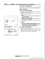
roller
Axle stand
hook
bar
Front
Anchor plate
SPEEDOMETER TEST
IF A FREE ROLLER IS USED
1.
Set the free roller on the floor (at the rear wheels) so that it
is aligned with the vehicle’s wheelbase and the rear tread.
2.
Carefully move the vehicle onto the tester and free roller.
3. Set the speedometer tester in place.
4. Perform the speedometer test.
For information concerning the measurement of speed and
the allowable error, refer to GROUP
and
Gauges.
Caution
Do not operate the clutch suddenly, or increase or
reduce speed suddenly during the work.
IF THE REAR WHEELS ARE JACKED UP
1. Move the vehicle onto the speedometer tester.
2.
Jack up the rear wheels, and place axle stands at the
designated part of the side sill.
3. Perform the speedometer test.
For information concerning the measurement of speed and
the allowable error, refer to GROUP
and
Gauges.
Caution
Do not operate the clutch suddenly, or increase or
reduce speed suddenly during the work.
Front wheel side slip
To prevent the front wheels from moving from side to side,
attach tension bars to the towing hooks, and secure both ends
at anchor plates.
Accident prevention procedures
(1) Attach a chain or wire to the rear traction hook. Make sure
the end of the wire or chain is secured firmly.
(2) Take all other necessary precautions.
BRAKE TEST
In order to stabilize the viscous coupling’s dragging force, the
brake test should always be conducted after the speedometer
test.
FRONT WHEEL MEASUREMENTS
1. Place the front wheels on the brake tester.
2. Perform the brake test.
Caution
The rear wheels should remain on the ground.
3. If the brake dragging force exceeds the specified value,
jack up the vehicle and manually rotate each wheel to
check the rotation condition of each wheel.
NOTE
If the brake dragging force exceeds the specified value, the
cause may be the effect of the viscous coupling’s dragging
force, so jack up the front wheels and check the rotation
condition of the wheels in this state for no effect by the
viscous coupling’s dragging force.
TSB Revision
Содержание 1989 Galant
Страница 2: ......
Страница 4: ...00 z NOTES ...
Страница 274: ...13 132 NOTE ...
Страница 282: ...13 140 On Vehicle Inspection of MFI FUEL SYSTEM SOHC 16 VALVE Components 6FU 0985 6FUO99 J TSB Revision ...
Страница 512: ...AUTO CRUISE CONTROL SYSTEM Troubleshooting Accelerator pedal switch 07R003E 1750407 TSB Revision ...
Страница 586: ...NOTES ...
Страница 650: ...NOTE ...
Страница 664: ...NOTES ...
Страница 688: ...NOTES ...
Страница 690: ......
Страница 692: ......
Страница 694: ......
Страница 696: ......
Страница 698: ......
Страница 700: ...c ...
Страница 702: ......
Страница 704: ......
Страница 706: ......
Страница 708: ......
Страница 710: ......
Страница 712: ......
Страница 714: ......
Страница 716: ......
Страница 718: ......
Страница 720: ......
Страница 722: ......
Страница 724: ......
Страница 729: ...23 23 NOTES ...
Страница 860: ...NOTES ...
Страница 921: ...NOTES ...
Страница 948: ...33B 9 NOTES ...
Страница 1016: ...ACTIVE ELECTRONIC CONTROL SUSPENSION Troubleshooting 33B 77 A 58 A 63 __ 111111111 Ground point detailed view TSB Revision ...
Страница 1021: ...33B 82 ACTIVE ELECTRONIC CONTROL SUSPENSION Troubleshooting INTERIOR 16AO353 crossmembe WA0492 1 TSB Revision I ...
Страница 1121: ...NOTES ...
Страница 1200: ...SERVICE BRAKES Brake Pedal 35 79 Lubrication points Part A 14AO256 1 14UOO5l TSB Revision ...
Страница 1273: ...NOTES t ...

