WELDING
BASE OF BODY REPAIR
9-7
Galvanized steel plate (SECC)
CAUTION
If the total thickness of the plates at the weld
places is 3 mm (0.1 inch) or more, use plug weld-
ing, because spot welding will not provide suffi-
cient welded strength.
*: For welding steel plates of different thicknesses,
conform to the welding conditions for the thinner
plate.
.
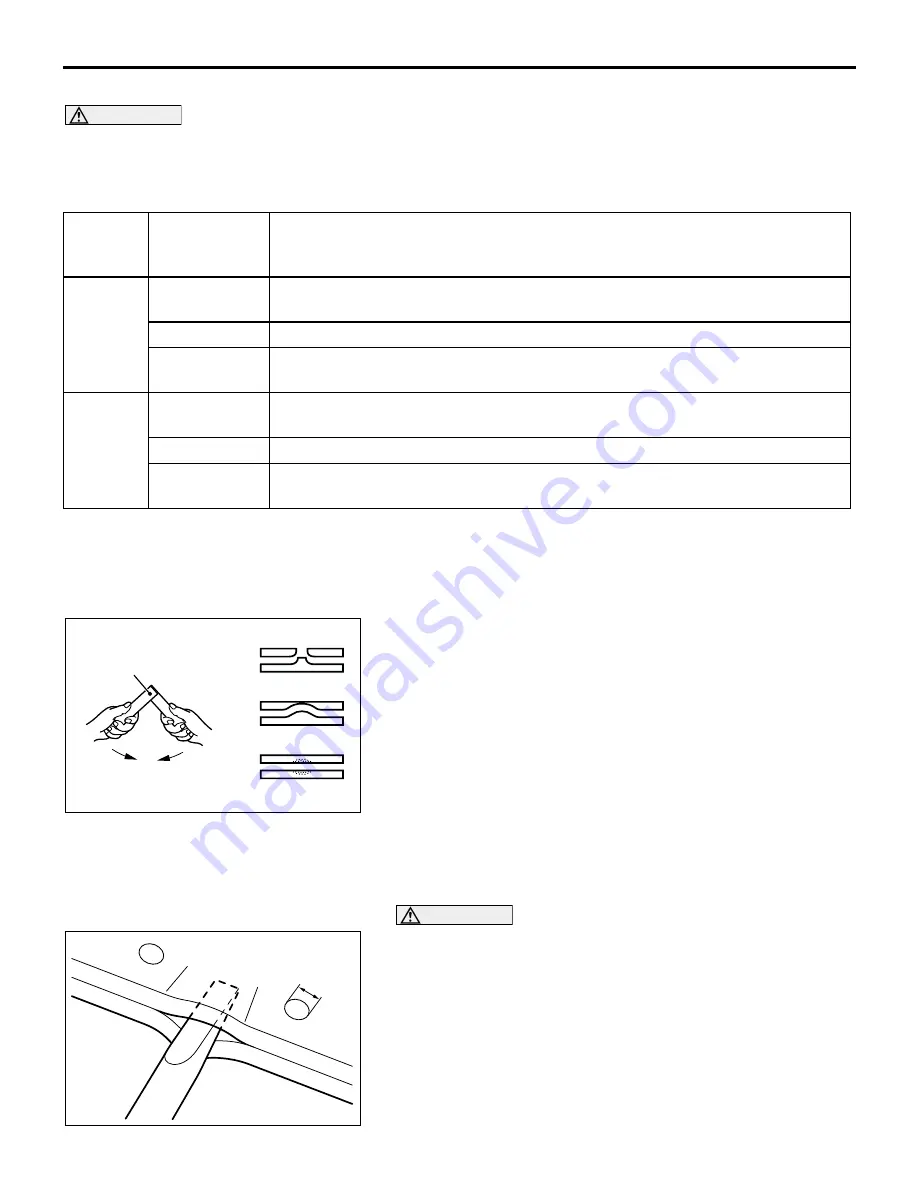
USING A TEST PIECE TO CHECK NUGGET FORMATION
Weld a test piece of the same type of steel plate as the panels
to be welded. Try to twist the piece, and also check the nugget
diameter.
Using the weld point as an axis, apply force in the direction indi-
cated by the arrows in the illustration, and determine the
strength of the weld.
1. Good (The welded part remains at one side.)
2. and 3.
The weld conditions are unsatisfactory; adjust the welding
current, the current application time, and/or the applied
pressure.
.
CHECKING NUGGET STRENGTH FOLLOWING SPOT
WELDING
CAUTION
•
Stop wedging the tip or the chisel or flat-tipped screw-
driver as soon as the size of the nuggets can be deter-
mined; do not wedge it in more than 30 mm (1.2
inches).
•
After checking the nugget diameter, correct the place
where the checking was done.
Wedge the tip of a chisel or flat-tipped (-) screwdriver into the
space between two weld points.
•
The nuggets should not break apart.
•
The nugget diameter should be 3 mm (0.1 inch) or more.
PANEL
THICKNESS*
[mm (in.)]
NUMBER OF REPAIR WELD (PERCENTAGE OF FACTORY WELD)
SAFETY
EQUIPM
ENT
AREA
0.9 (0.04) or
less
100% Same number as factory welds
1.0 (0.04)
200% Maintain pitch of at least 18 mm (0.7 inch); if not possible, plug weld.
1.2 (0.05) or
more
100% Same number as factory welds; plug welding
OTHER
AREA
0.9 (0.04) or
less
100% Same number as factory welds
1.0 (0.04)
140% Maintain pitch of at least 18 mm (0.7 inch); if not possible, plug weld.
1.2 (0.05) or
more
100% Same number as factory welds; plug welding
AB200032AB
WELD POINT
1
2
3
AB200033AB
3 mm (0.1 in)
Содержание Lancer Evolution VIII 2003
Страница 14: ...36 1 GROUP 36 PARKING BRAKE CONTENTS GENERAL INFORMATION 36 2 ...
Страница 26: ...35 1 GROUP 35 SERVICE BRAKES CONTENTS SERVICE BRAKES 35A FOUR WHEEL ANTI LOCK BRAKE SYSTEM 4ABS 35B ...
Страница 27: ...NOTES ...
Страница 34: ...34 1 GROUP 34 REAR SUSPENSION CONTENTS GENERAL DESCRIPTION 34 2 ...
Страница 37: ...NOTES ...
Страница 38: ...33A 1 GROUP 33A FRONT SUSPENSION CONTENTS GENERAL DESCRIPTION 33A 2 LOWER ARM 33A 4 STRUT ASSEMBLY 33A 5 ...
Страница 43: ...NOTES ...
Страница 57: ...NOTES ...
Страница 58: ...31 1 GROUP 31 WHEEL AND TIRE CONTENTS GENERAL INFORMATION 31 2 ...
Страница 60: ...21 1 GROUP 21 CLUTCH CONTENTS GENERAL DESCRIPTION 21 2 ...
Страница 70: ...27 1 GROUP 27 REAR AXLE CONTENTS REAR AXLE 27 2 DIFFERENTIAL 27 3 ...
Страница 74: ...54 1 GROUP 54 CHASSIS ELECTRICAL CONTENTS CHASSIS ELECTRICAL 54A SIMPLIFIED WIRING SYSTEM SWS 54B ...
Страница 75: ...NOTES ...
Страница 85: ...NOTES ...
Страница 94: ...26 1 GROUP 26 FRONT AXLE CONTENTS GENERAL DESCRIPTION 26 2 ...
Страница 114: ...11A 1 GROUP 11A ENGINE CONTENTS GENERAL SPECIFICATIONS 11A 2 BASE ENGINE 11A 3 ...
Страница 119: ...NOTES ...
Страница 126: ...13B 1 GROUP 13B FUEL SUPPLY CONTENTS GENERAL DESCRIPTION 13B 2 FUEL TANK 13B 3 ...
Страница 129: ...NOTES ...
Страница 130: ...25 1 GROUP 25 PROPELLER SHAFT CONTENTS GENERAL DESCRIPTION 25 2 ...
Страница 132: ...16 1 GROUP 16 ENGINE ELECTRICAL CONTENTS CAMSHAFT POSITION SENSOR 16 2 ...
Страница 134: ...12 1 GROUP 12 ENGINE LUBRICATION CONTENTS GENERAL DESCRIPTION 12 2 ...
Страница 142: ...32 1 GROUP 32 POWER PLANT MOUNT CONTENTS GENERAL DESCRIPTION 32 2 ...
Страница 144: ...14 1 GROUP 14 ENGINE COOLING CONTENTS GENERAL DESCRIPTION 14 2 ...
Страница 146: ...52 1 GROUP 52 INTERIOR AND SUPPLEMENTAL SYSTEM SRS CONTENTS INTERIOR 52A SUPPLEMENTAL RESTRAINT SYSTEM SRS 52B ...
Страница 147: ...NOTES ...
Страница 161: ...NOTES ...
Страница 162: ...13 1 GROUP 13 FUEL CONTENTS MULTIPORT FUEL SYSTEM MFI 13A FUEL SUPPLY 13B ...
Страница 163: ...NOTES ...
Страница 177: ...NOTES ...
Страница 178: ...22A 1 GROUP 22A MANUAL TRANSAXLE CONTENTS GENERAL DESCRIPTION 22A 2 AWD SYSTEM 22A 4 TRANSMISSION CONTROL 22A 5 ...
Страница 183: ...NOTES ...
Страница 203: ...7 1 GROUP 7 WIRING AND PIPING DIAGRAM CONTENTS PIPING DIAGRAM 7 2 ...
Страница 246: ...NOTES ...
Страница 260: ...NOTES ...
Страница 264: ...NOTES ...
Страница 265: ...5 1 GROUP 5 SYNTHETIC RESIN PARTS CONTENTS LOCATION OF SYNTHETIC RESIN PARTS 5 2 ...
Страница 268: ...NOTES ...
Страница 276: ...NOTES ...
Страница 281: ...FENDER SHIELD WELDED PANEL REPLACEMENT 3 5 AB202219 C B C D E D AB WITH THE UPPER FRAME EXTENSION OUTER REMOVED B ...
Страница 283: ...FENDER SHIELD WELDED PANEL REPLACEMENT 3 7 NOTES ...
Страница 368: ...NOTES ...


