


BODY REPAIR
BASE OF BODY REPAIR
9-21
CAUTION
Wipe off any anticorrosion agent which oozes out onto
surfaces to be painted later; the presence of such anticor-
rosion agent would prevent correct adhesion of the paint
coat.
20.
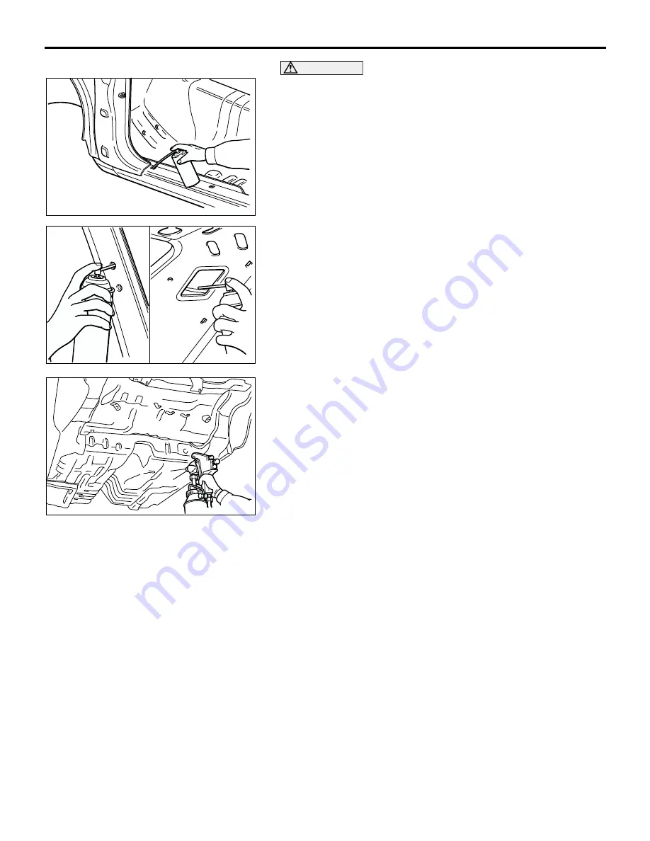
Application of an anticorrosion agent
Apply an ample amount of anticorrosion agent to any
welded areas and to all surfaces from which the paint coat
was removed.
The paint coat of welded areas will have been damaged by
the heat; be sure to apply an anticorrosion agent to surfaces
to be repaired.
Use an aerosol-type anticorrosion agent for application to
the side sills, the pillars, and other similar parts which have a
hollow construction, by utilizing the trim mounting holes, etc.
21.
Application of undercoating
If the underbody is repaired or replaced, carefully apply a
coating of undercoating as described in the section (of the
manual corresponding to that model).
CAUTIONS REGARDING BODY REPAIR
Because each component part of a single-unit con-
struction body makes some contribution, more or
less, to the overall strength of that body, it is neces-
sary to sufficiently understand the actual function of
any part to be repaired before attempting any repair
or welding procedure.
.
STRENGTH AND RIGIDITY
1. The suspension installation part plays an impor-
tant role, determining the wheel alignment. Wheel
misalignment is of course potentially vary danger-
ous because it can lead to driving instability, one-
sided braking, abnormal tire wear, abnormal
vibration, etc.
At the time of repair, it is particularly necessary to
take measurements at the components noted
below, and to make all welds and installations
with special care.
•
Front sidemember
•
Rear floor sidemember
•
Front wheelhouse (inner)
•
Rear wheelhouse (inner) (Independent rear
suspension type)
2. Because the places where the floor panel and
sidemember parts are joined have an important
effect upon the rigidity of the entire body, welds in
these places must be done with particular care.
3. After repairs have been completed, the wheel
alignment, wheel base, tread, etc., must be care-
fully checked to be sure that there is no deviation.
.
AB200077
AB200078
AB200079
Содержание Lancer Evolution VIII 2003
Страница 14: ...36 1 GROUP 36 PARKING BRAKE CONTENTS GENERAL INFORMATION 36 2 ...
Страница 26: ...35 1 GROUP 35 SERVICE BRAKES CONTENTS SERVICE BRAKES 35A FOUR WHEEL ANTI LOCK BRAKE SYSTEM 4ABS 35B ...
Страница 27: ...NOTES ...
Страница 34: ...34 1 GROUP 34 REAR SUSPENSION CONTENTS GENERAL DESCRIPTION 34 2 ...
Страница 37: ...NOTES ...
Страница 38: ...33A 1 GROUP 33A FRONT SUSPENSION CONTENTS GENERAL DESCRIPTION 33A 2 LOWER ARM 33A 4 STRUT ASSEMBLY 33A 5 ...
Страница 43: ...NOTES ...
Страница 57: ...NOTES ...
Страница 58: ...31 1 GROUP 31 WHEEL AND TIRE CONTENTS GENERAL INFORMATION 31 2 ...
Страница 60: ...21 1 GROUP 21 CLUTCH CONTENTS GENERAL DESCRIPTION 21 2 ...
Страница 70: ...27 1 GROUP 27 REAR AXLE CONTENTS REAR AXLE 27 2 DIFFERENTIAL 27 3 ...
Страница 74: ...54 1 GROUP 54 CHASSIS ELECTRICAL CONTENTS CHASSIS ELECTRICAL 54A SIMPLIFIED WIRING SYSTEM SWS 54B ...
Страница 75: ...NOTES ...
Страница 85: ...NOTES ...
Страница 94: ...26 1 GROUP 26 FRONT AXLE CONTENTS GENERAL DESCRIPTION 26 2 ...
Страница 114: ...11A 1 GROUP 11A ENGINE CONTENTS GENERAL SPECIFICATIONS 11A 2 BASE ENGINE 11A 3 ...
Страница 119: ...NOTES ...
Страница 126: ...13B 1 GROUP 13B FUEL SUPPLY CONTENTS GENERAL DESCRIPTION 13B 2 FUEL TANK 13B 3 ...
Страница 129: ...NOTES ...
Страница 130: ...25 1 GROUP 25 PROPELLER SHAFT CONTENTS GENERAL DESCRIPTION 25 2 ...
Страница 132: ...16 1 GROUP 16 ENGINE ELECTRICAL CONTENTS CAMSHAFT POSITION SENSOR 16 2 ...
Страница 134: ...12 1 GROUP 12 ENGINE LUBRICATION CONTENTS GENERAL DESCRIPTION 12 2 ...
Страница 142: ...32 1 GROUP 32 POWER PLANT MOUNT CONTENTS GENERAL DESCRIPTION 32 2 ...
Страница 144: ...14 1 GROUP 14 ENGINE COOLING CONTENTS GENERAL DESCRIPTION 14 2 ...
Страница 146: ...52 1 GROUP 52 INTERIOR AND SUPPLEMENTAL SYSTEM SRS CONTENTS INTERIOR 52A SUPPLEMENTAL RESTRAINT SYSTEM SRS 52B ...
Страница 147: ...NOTES ...
Страница 161: ...NOTES ...
Страница 162: ...13 1 GROUP 13 FUEL CONTENTS MULTIPORT FUEL SYSTEM MFI 13A FUEL SUPPLY 13B ...
Страница 163: ...NOTES ...
Страница 177: ...NOTES ...
Страница 178: ...22A 1 GROUP 22A MANUAL TRANSAXLE CONTENTS GENERAL DESCRIPTION 22A 2 AWD SYSTEM 22A 4 TRANSMISSION CONTROL 22A 5 ...
Страница 183: ...NOTES ...
Страница 203: ...7 1 GROUP 7 WIRING AND PIPING DIAGRAM CONTENTS PIPING DIAGRAM 7 2 ...
Страница 246: ...NOTES ...
Страница 260: ...NOTES ...
Страница 264: ...NOTES ...
Страница 265: ...5 1 GROUP 5 SYNTHETIC RESIN PARTS CONTENTS LOCATION OF SYNTHETIC RESIN PARTS 5 2 ...
Страница 268: ...NOTES ...
Страница 276: ...NOTES ...
Страница 281: ...FENDER SHIELD WELDED PANEL REPLACEMENT 3 5 AB202219 C B C D E D AB WITH THE UPPER FRAME EXTENSION OUTER REMOVED B ...
Страница 283: ...FENDER SHIELD WELDED PANEL REPLACEMENT 3 7 NOTES ...
Страница 368: ...NOTES ...