


WELDING
BASE OF BODY REPAIR
9-11
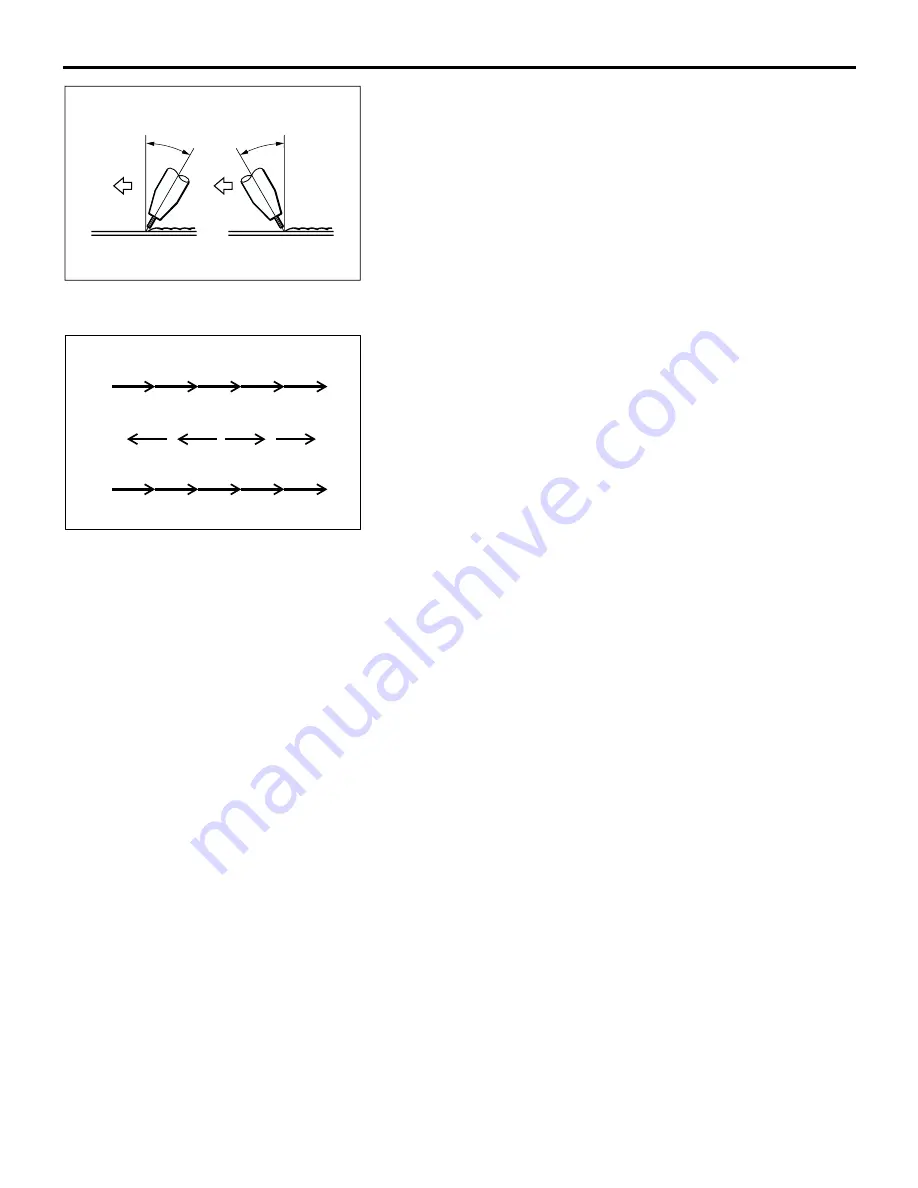
The angle of the torch should be 15 degree angle to 30 degree
angle for either technique, and the tip should be maintained at
a distance of 6 to 10 mm (0.2 to 0.4 inch) from the surface
being welded.
.
Preventing warping
1. Backhand technique
Because the direction for each weld pass and that for the
fusion progression are opposite, the residual stress is
evenly distributed.
2. Symmetrical technique
Because the welds are made in symmetrical positions in
relation to the centre of the joint, the residual stress is also
symmetrical.
3. "Stepping stone" technique
Because the welds are made at random positions, the
residual stress is the most evenly distributed; however, the
possibility of flaws at the starting and stopping points is rela-
tively high.
NOTES REGARDING MIG WELDING
Note the following notes regarding MIG welding.
1. The surface to be welded must be perfectly
clean; be sure to remove any non-conductive
paint.
2. If the end of the wire forms into a ball, it will
adversely affect the formation of the arc; cut the
end off with a pair of wire snips or a similar tool.
3. Select a welding current to match the thickness of
the panels being welded.
4. For continuous welding, maintain a constant weld
speed and keep both the height and the width of
the bead constant.
In addition, the tack welding pitch and the welding
bead should be shorter as the thickness of the
panels being welded decreases.
OTHER TYPES OF WELDING
M4090004000013
BRAZING
In brazing, a filler metal is melted into the joint of the
panels to be welded at a comparatively low tempera-
ture to fuse them together without melting the panels
themselves. In other words, through the aid of a flux
and because of the capillarity phenomenon, the mol-
ten filler metal will flow into the joint between the two
panels which are in contact with each other and
spread along the metal surfaces. When this molten
filler metal cools and solidifies, it will from a strong
joint of the two panels. Note that, if two panels of dif-
ferent kinds of metal are brazed, the electrolysis gen-
erated between the two metals will cause moisture to
from, which will result in corrosion.
Panels should not be connected together by brazing
at any place except those places indicated. The fol-
lowing materials (filler metals) are usually used for
brazing.
1.
Brass filler metal (brass solder)
Brass filler metal is an alloy consisting of 60%
copper and 40% zinc with a melting temperature
of approximately 850 to 1,050
°
C (1,562 to
1,922
°
F), and it is the most commonly used braz-
ing filler metal used for body repair.
The filler metal itself is coated with flux to facili-
tate penetration between the panels to be joined.
AB200042
15
˚
- 30
˚
15
˚
- 30
˚
FOREHAND
TECHNIQUE
BACKHAND
TECHNIQUE
AB
AB200043 AB
ANTI-WARP WELDING TECHNIQUES
1.
2.
3.
BACKHAND TECHNIQUE
SYMMETRICAL TECHNIQUE
"STEPPING STONE" TECHNIQUE
5
4
3
2
1
5
4
3
2
1
4
3
2
1
Содержание Lancer Evolution VIII 2003
Страница 14: ...36 1 GROUP 36 PARKING BRAKE CONTENTS GENERAL INFORMATION 36 2 ...
Страница 26: ...35 1 GROUP 35 SERVICE BRAKES CONTENTS SERVICE BRAKES 35A FOUR WHEEL ANTI LOCK BRAKE SYSTEM 4ABS 35B ...
Страница 27: ...NOTES ...
Страница 34: ...34 1 GROUP 34 REAR SUSPENSION CONTENTS GENERAL DESCRIPTION 34 2 ...
Страница 37: ...NOTES ...
Страница 38: ...33A 1 GROUP 33A FRONT SUSPENSION CONTENTS GENERAL DESCRIPTION 33A 2 LOWER ARM 33A 4 STRUT ASSEMBLY 33A 5 ...
Страница 43: ...NOTES ...
Страница 57: ...NOTES ...
Страница 58: ...31 1 GROUP 31 WHEEL AND TIRE CONTENTS GENERAL INFORMATION 31 2 ...
Страница 60: ...21 1 GROUP 21 CLUTCH CONTENTS GENERAL DESCRIPTION 21 2 ...
Страница 70: ...27 1 GROUP 27 REAR AXLE CONTENTS REAR AXLE 27 2 DIFFERENTIAL 27 3 ...
Страница 74: ...54 1 GROUP 54 CHASSIS ELECTRICAL CONTENTS CHASSIS ELECTRICAL 54A SIMPLIFIED WIRING SYSTEM SWS 54B ...
Страница 75: ...NOTES ...
Страница 85: ...NOTES ...
Страница 94: ...26 1 GROUP 26 FRONT AXLE CONTENTS GENERAL DESCRIPTION 26 2 ...
Страница 114: ...11A 1 GROUP 11A ENGINE CONTENTS GENERAL SPECIFICATIONS 11A 2 BASE ENGINE 11A 3 ...
Страница 119: ...NOTES ...
Страница 126: ...13B 1 GROUP 13B FUEL SUPPLY CONTENTS GENERAL DESCRIPTION 13B 2 FUEL TANK 13B 3 ...
Страница 129: ...NOTES ...
Страница 130: ...25 1 GROUP 25 PROPELLER SHAFT CONTENTS GENERAL DESCRIPTION 25 2 ...
Страница 132: ...16 1 GROUP 16 ENGINE ELECTRICAL CONTENTS CAMSHAFT POSITION SENSOR 16 2 ...
Страница 134: ...12 1 GROUP 12 ENGINE LUBRICATION CONTENTS GENERAL DESCRIPTION 12 2 ...
Страница 142: ...32 1 GROUP 32 POWER PLANT MOUNT CONTENTS GENERAL DESCRIPTION 32 2 ...
Страница 144: ...14 1 GROUP 14 ENGINE COOLING CONTENTS GENERAL DESCRIPTION 14 2 ...
Страница 146: ...52 1 GROUP 52 INTERIOR AND SUPPLEMENTAL SYSTEM SRS CONTENTS INTERIOR 52A SUPPLEMENTAL RESTRAINT SYSTEM SRS 52B ...
Страница 147: ...NOTES ...
Страница 161: ...NOTES ...
Страница 162: ...13 1 GROUP 13 FUEL CONTENTS MULTIPORT FUEL SYSTEM MFI 13A FUEL SUPPLY 13B ...
Страница 163: ...NOTES ...
Страница 177: ...NOTES ...
Страница 178: ...22A 1 GROUP 22A MANUAL TRANSAXLE CONTENTS GENERAL DESCRIPTION 22A 2 AWD SYSTEM 22A 4 TRANSMISSION CONTROL 22A 5 ...
Страница 183: ...NOTES ...
Страница 203: ...7 1 GROUP 7 WIRING AND PIPING DIAGRAM CONTENTS PIPING DIAGRAM 7 2 ...
Страница 246: ...NOTES ...
Страница 260: ...NOTES ...
Страница 264: ...NOTES ...
Страница 265: ...5 1 GROUP 5 SYNTHETIC RESIN PARTS CONTENTS LOCATION OF SYNTHETIC RESIN PARTS 5 2 ...
Страница 268: ...NOTES ...
Страница 276: ...NOTES ...
Страница 281: ...FENDER SHIELD WELDED PANEL REPLACEMENT 3 5 AB202219 C B C D E D AB WITH THE UPPER FRAME EXTENSION OUTER REMOVED B ...
Страница 283: ...FENDER SHIELD WELDED PANEL REPLACEMENT 3 7 NOTES ...
Страница 368: ...NOTES ...