- 197 -
Alternate
display
Date
Month
Year
❉
This function is not compatible with some units.
Notes: 1. This is a simple clock function so the time should be used only for reference.
2.
3.
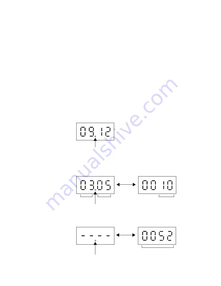
Reading the time data:
• For time display
Example : 9 hours 12 minutes
• Date display
(1) When upward controller that can set time is connected
Example : May 10, 2003
(2) When upward controller that can set time is not connected
Example : 52 days after power was turned ON
Alternate
display
Day count
" . " disappears if the time data is deviated due to a power failure,
or if a system controller for setting the time is not connected.
❉
The year and month display uses " . ". The date display has no " . ".
❉
The year and month display uses " . ". The date display has no " . ".
The outdoor unit has a simple clock function to receive the time setting from the system controller, such as the G50A,
and count the current time with an internal timer.
If an error (prediction) occurs, the error history data and the error detection time are saved in the service memory.
The error detection time saved in the service memory and the current time can be confirmed with the service LEDs.
The date and time data is all set to 00 as the default.
If a system controller that sets the time in the outdoor unit, such as the G50A, is not connected, the time
and days elapsed from the first time the power was turned on will be displayed.
If the time setting has been received, the count will start from the set date and time.
The time data is not updated when the outdoor unit's power is off. When the power is turned off and then
on again, the count will resume from the time before the power was turned off. Thus, a time differing from
the actual time will be saved. (This also applies when a power failure occurs)
The system controller, such as the G50A, sets the time once a day. Thus, if this type of system
controller is connected, the time will be updated to the correct time after the settings are received.
(The data stored in the memory before the settings are received will not be corrected.)
3. Time data storage function
Содержание PURY-P200
Страница 49: ... 46 Heat exchanger Fan guard Heat exchanger Fan guard P400 type Front view of the unit Rear view of the unit ...
Страница 57: ... 54 CNVDC DC bus voltage input 1 3 LED1 LED2 SW2 CNTR IPM back CNN Fan motor output Fuse CNRS2 3 FAN board ...
Страница 64: ... 61 Relay board RELAY 4 board Relay board RELAY 10 board ...


