Mitsubishi Electric PAC-IF033B-E Скачать руководство пользователя страница 34

MITSUBISHI ELECTRIC CORPORATION 

TOKYO BUILDING, 2-7-3, MARUNOUCHI, CHIYODA-KU, TOKYO 100-8310, JAPAN

MITSUBISHI ELECTRIC, PAC-IF033B-E

2014/35/EU: Low Voltage

2014/30/EU: Electromagnetic Compatibility

2011/65/EU, (EU) 2015/863 and (EU) 2017/2102: RoHS Directive

Issued
JAPAN

Katsuo YABUTA
Senior Manager, Quality Assurance Department

1 Dec. 2019

EC DECLARATION OF CONFORMITY

EG-KONFORMITÄTSERKLÄRUNG

DÉCLARATION DE CONFORMITÉ CE

EG-CONFORMITEITSVERKLARING

DECLARACIÓN DE CONFORMIDAD CE

DICHIARAZIONE DI CONFORMITÀ CE

ΔΗΛΩΣΗ ΠΙΣΤΟΤΗΤΑΣ ΕΚ

DECLARAÇÃO DE CONFORMIDADE CE

EU-OVERENSSTEMMELSESERKLÆRING

EG-DEKLARATION OM ÖVERENSSTÄMMELSE

EC UYGUNLUK BEYANI

ДЕКЛАРАЦИЯ СООТВЕТСТВИЯ НОРМАМ ЕС

ДЕКЛАРАЦІЯ ВІДПОВІДНОСТІ НОРМАМ ЄС

EC ДЕКЛАРАЦИЯ ЗА СЪОТВЕТСТВИЕ

DEKLARACJA ZGODNOŚCI WE

CE-ERKLÆRING OM SAMSVAR

EY-VAATIMUSTENMUKAISUUSVAKUUTUS

ES PROHLÁŠENÍ O SHODĚ

VYHLÁSENIE O ZHODE ES

EK MEGFELELŐSÉGI NYILATKOZAT

IZJAVA O SKLADNOSTI ES

DECLARAŢIE DE CONFORMITATE CE

EÜ VASTAVUSDEKLARATSIOON

EK ATBILSTĪBAS DEKLARĀCIJA

EB ATITIKTIES DEKLARACIJA

EC IZJAVA O SUKLADNOSTI

EZ IZJAVA O USAGLAŠENOSTI

hereby declares under its sole responsibility that the heating system components described below for use in residential, commercial and light-industrial environments:

erklärt hiermit auf seine alleinige Verantwortung, dass die unten beschriebenen Zubehörteile für das Heizungs-System zur Benutzung im häuslichen, kommerziellen und leicht-industriellen Umfeld:

déclare par la présente et sous son entière responsabilité que les composants du système de chauffage décrits ci-dessous pour l’utilisation dans des environnements résidentiels, commerciaux et 

d’industrie légère :

verklaart hierbij als enige verantwoordelijke dat de componenten van het verwarmingssteem die hieronder worden beschreven, bedoeld zijn voor gebruik in woonomgevingen en in commerciële en licht 

industriële omgevingen:

declara por la presente bajo su responsabilidad exclusiva que los componentes del sistema de calefacción descritos a continuación para su uso en zonas residenciales, comerciales y para la industria 

ligera:

con la presente dichiara, sotto la sua esclusiva responsabilità, che i componenti dell’impianto di riscaldamento descritto di seguito, destinato all’uso in ambienti residenziali, commerciali e industriali:

διά του παρόντος δηλώνει υπό αποκλειστική ευθύνη της ότι τα εξαρτήματα του συστήματος θέρμανσης που περιγράφονται παρακάτω για χρήση σε κατοικημένες, εμπορικές και ελαφριές βιομηχανικές

περιοχές.

através da presente declara sob sua única responsabilidade que os componentes do sistema de aquecimento abaixo descritos para uso residencial, comercial e de indústria ligeira:

erklærer hermed under eneansvar, at de herunder beskrevne komponenter til opvarmning til brug i privat boligbyggeri, erhvervsområder og inden for let industri:

intygar härmed att uppvärmningssystemkomponenterna som beskrivs nedan är för användning i bostäder, kommersiella miljöer och lätt industri:

aşağıda anlatılan ısıtma sistemi bileşenlerinin konutlarda, ticari ve hafif sanayi ortamlarında kullanıma yönelik olduğunu tamamen kendi sorumluluğunda beyan eder:

настоящим заявляет и берет на себя исключительную ответственность за то, что кондиционеры и тепловые насосы, описанные ниже и предназначенные для эксплуатации в жилых помеще

-

ниях, торговых залах и на предприятиях легкой промышленности:

заявляє виключно під власну відповідальність, що компоненти системи опалення, описані нижче, призначені для використання в побутовому, комерційному та наближеному до промислового 

середовищах.

с настоящото декларира на своя отговорност, че описаните по-долу компоненти за отоплителна система са годни за експлоатация в жилищна, търговска и лекопромишлена среда:

niniejszym oświadcza na swoją wyłączną odpowiedzialność, że klimatyzatory i pompy ciepła opisane poniżej, są przeznaczone do zastosowań w środowisku mieszkalnym, handlowym

i lekko uprzemysłowionym:

erklærer hermed som sitt ansvar, ene og alene, at komponentene i varmesystemet som beskrives nedenfor og som er beregnet for bruk i bolig-, forretnings- og lettindustrimiljøer:

vakuuttaa täten asiasta yksin vastuussa, että alla kuvatut lämmitysjärjestelmän osat, jotka on tarkoitettu käytettäviksi asuin-, toimisto- ja kevyen teollisuuden ympäristöissä:

tímto na vlastní odpovědnost prohlašuje, že níže popsané klimatizační jednotky a tepelná čerpadla pro použití v obytných prostředích, komerčních prostředích a prostředích lehkého

průmyslu:

týmto vyhlasuje na vlastnú zodpovednosť, že komponenty vykurovacieho systému opísané nižšie pre použitie v obytných, komerčných a ľahkých priemyselných oblastiach:

ezennel kizárólagos felelősséggel kijelenti, hogy az alábbiakban leírt, lakó-, kereskedelmi és könnyűipari környezetben használható fűtőrendszer alkatrészei:

s tem izrecno izjavljamo, da so spodaj opisane komponente ogrevalnega sistema za uporabo v stanovanjskih, poslovnih in lahkoindustrijskih okoljih:

Prin prezentul document, compania declară pe propria răspundere că piesele sistemului de încălzire descrise mai jos sunt potrivite pentru utilizarea în medii rezidenţiale, comerciale şi uşor industriale:

kinnitab oma ainuvastutusel, et allpool kirjeldatud küttesüsteemi komponendid on mõeldud kasutamiseks elu-, kaubandus- ja kergetööstuskeskkonnas:

ar šo pilnībā atbild par to, ka tālāk aprakstītie apsildes sistēmas komponenti, kas izmantojami dzīvojamās, komerciālās un vieglās industriālās vidēs:

prisiimdamas visą atsakomybę pareiškia, kad žemiau aprašyti šildymo sistemos komponentai skirti naudoti gyvenamojoje, komercinėje ir lengvosios pramonės aplinkose:

ovime izjavljuje pod isključivo svojom odgovornošću da dolje opisane komponente sustava za grijanje za upotrebu u stambenim, komercijalnim i lakoindustrijskim okruženjima:

ovim izjavljujemo pod svojom isključivom odgovornošću da su opisane komponente sistema grejanja za upotrebu u stambenim, poslovnim i lakim industrijskim okruženjima:

Directives

Richtlinien

Directives

Richtlijnen

Directivas

Direttive

Οδηγίες

Directivas

Direktiver

Direktiv

Direktifler

Директивы

Директиви

Директиви

Dyrektywy

Direktiver

Direktiivit

Směrnice

Smernice

Irányelvek

Direktive

Directive

Direktiivid

Direktīvas

Direktyvos

Direktive

Direktive

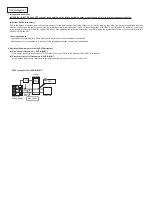
Note: Its serial number is on the nameplate of the product.

Hinweis: Die Seriennummer befindet sich auf dem Kennschild des Produkts.

Remarque : Le numéro de série de l’appareil se trouve sur la plaque du produit.

Opmerking: het serienummer staat op het naamplaatje van het product.

Nota: El número de serie se encuentra en la placa que contiene el nombre del producto.

Nota: il numero di serie si trova sulla targhetta del prodotto.

Σημείωση: Ο σειριακός του αριθμός βρίσκεται στην πινακίδα ονόματος του προϊόντος.

Nota: o número de série encontra-se na placa que contém o nome do produto.

Bemærk: Serienummeret står på produktets fabriksskilt.

Obs: Serienumret finns på produktens namnplåt.

Not: Seri numarası ürünün isim plakasında yer alır.

Примечание: серийный номер указан на паспортное табличке изделия.

Примітка. Серійний номер вказано на паспортній табличці виробу.

Забележка: Серийният му номер е на табелката на продукта.

Uwaga: Numer seryjny znajduje się na tabliczce znamionowej produktu.

Merk: Serienummeret befinner seg på navneplaten til produktet. 

Huomautus: Sarjanumero on merkitty laitteen arvokilpeen. 

Poznámka: Příslušné sériové číslo se nachází na štítku produktu.

Poznámka: Výrobné číslo sa nachádza na typovom štítku výrobku.

Megjegyzés: A sorozatszám a termék adattábláján található.

Opomba: serijska številka je zapisana na tipski ploščici enote.

Notă: Numărul de serie este specificat pe plăcuţa indicatoare a produsului.

Märkus. Seerianumber asub toote andmesildil.

Piezīme. Sērijas numurs ir norādīts uz ierīces datu plāksnītes.

Pastaba. Serijos numeris nurodytas gaminio vardinių duomenų lentelėje.

Napomena: serijski broj nalazi se na natpisnoj pločici proizvoda.

Napomena: Serijski broj nalazi se na nazivnoj pločici proizvoda.

Содержание PAC-IF033B-E

Страница 1: ...English FLOW TEMP CONTROLLER 2BR Cased PAC IF033B E INSTALLATION MANUAL For safe and correct use read this manual thoroughly before installing the FTC2BR unit FOR INSTALLER ...

Страница 2: ...an unusual environment If the FTC2BR unit is installed or exposed to steam volatile oil including machine oil or sulfuric gas or exposed to briny air the internal parts can be damaged Do not install the unit where combustible gases may leak be produced flow or accumulate If combustible gas accumulates around the unit it may cause fire or explosion When installing the unit in a hospital or in a bui...

Страница 3: ... the weight and vibration of the unit Avoid locations where the unit is exposed to oil steam or sulfuric gas Do not install in location that is hot or humid for long periods of time Fig 2 1 1 22 11 5 Unit mm 11 5 5 12 10 200 313 3 ELECTRIC WIRE INLET When installed on a wall Lower side 278 336 69 TB143 TB141 TB142 C C C C TB6 Fig 2 3 4 Top Bottom Pull the cover to the front and remove it Slide the...

Страница 4: ...1 4 4 2 External input and analog input Outdoor unit only Local controller External input Analog signal Local controller 4 1 Power supplies Operation mode input Outdoor unit FTC2BR Remote controller Outdoor unit FTC2BR Remote controller Local controller ON OFF MODE Local controller ON OFF MODE Temp Outdoor unit FTC2BR The FTC2BR is designed for use with a number of heat pump systems Please refer t...

Страница 5: ...Return water temp Packaged type 4 3 4 3 4 3 4 3 Thermistor Outdoor unit FTC2BR DHW tank THW5 Heat exchanger Outdoor unit FTC2BR Heat exchanger THW1 THW1 THW1 THW1 Outdoor unit FTC2BR DHW tank THW5 Heat emitter Heat emitter Heat emitter Heat emitter TH2 THW2 THW2 THW2 THW2 Heat exchanger Outdoor unit FTC2BR TH2 Heat exchanger Present Present Absent Absent Outdoor unit type DHW tank 3 2 Second step ...

Страница 6: ...t Absent 4 4 4 4 3 4 4 4 4 3 4 4 4 4 3 3 3 Third step Heater setting Immersion heater Booster heater position Note When the booster heater is positioned for heating only flow water temp thermistor THW1 is not able to detect the outlet water temperature of circulation water during DHW or legionella prevention mode To determine more accurately if the heater is ON with DHW or legionella prevention mo...

Страница 7: ...y Connect the surge absorber according to the load at site Separate power for heater Install an earth leakage circuit breaker for heater separate from control power Heater capacity Breaker wiring recommended Description Power supply Capacity Breaker Wiring Immersion heater DHW tank N 230V 50Hz 3 kW 16 A 2 5 mm When installing an immersion heater with the capacity of bigger than shown above select ...

Страница 8: ...echnician Failure to comply with this could lead to electrocution fire and death It will also invalidate product warranty All wiring should be according to national wiring regulations Connections should be made to the terminals indicated in the following figures de pending on the phase When the wires are wired to adjacent terminals use ring terminals and insu late the wires Option 1 FTC2BR powered...

Страница 9: ...r units have separate power supplies the following requirements MUST carried out Remove the short circuited connector CNS2 Turn on the outdoor unit before the FTC2BR Outdoor unit DIP switch settings changed to SW8 3 ON Power by independent source is not available for particular models of outdoor unit model For more detail refer to the connecting outdoor unit installation manual Notes 1 Do not run ...

Страница 10: ... the remote controller either directly on the wall or in the switch box 2 Prepare the following items in the field Double switch box Thin metal conduit Locknut and bushing Cable cover Wall plug 2 Drill an installation hole in the wall Installation using a switch box Drill a hole in the wall for the switch box and install the switch box in the hole Fit the conduit tube into the switch box Direct wa...

Страница 11: ... remote controller do not overtighten the screws and make an additional installation hole s 6 Cut out the cable access hole Direct wall installation Cut out the knockout hole indicated with grey in Fig 4 2 7 in the cosmetic cover by knife or nipper Thread the remote controller cable from the slot behind the back cover through this access hole 7 Plug the lead wire cable into the front cover Plug th...

Страница 12: ... along the wall surface Thread the remote controller cable through the cable access hole at the top of the remote controller Seal the gap between the cable and the access hole with putty Use a cable cover Disassembling the front cover and the cosmetic cover 1 Remove the cosmetic cover Insert a flat head screwdriver into either of two open slots at the bottom of the remote controller and move the s...

Страница 13: ...it Thermistor position Place THW1 on water piping water outlet side after booster heater and THW2 on the water inlet side It is recommended to protect the thermistor with heat insulating materials so as not to be affected by ambient temperature Note Be sure to attach THW1 where it correctly detects Flow temp water oulet side 4 3 3 Connecting the actual DHW tank thermistor THW5 cable Connect the TH...

Страница 14: ...booster heater piping SPLIT type without a refrigerant water HEX inside 1 Refrigerant water HEX DHW tank temperature Water OUTLET side after booster heater Water piping Water INLET side THW1 TH2 THW5 THW2 1 FTC2BR FTC2BR FTC2BR FTC2BR Outdoor unit SPLIT type outdoor unit with booster heater THW1 TH2 THW2 THW5 Not necessary 1 Refrigerant Refrigerant LIQUID side piping SPLIT type without a refrigera...

Страница 15: ...DHW mode Input signal Pulse Pulse specifications ON short OFF open When SW1 1 or SW1 2 or both are ON the mode is switched into DHW mode 4 4 2 External inputs Analog signal 4 20mA 1 5V 0 10V Connect the transmission cables to No 11 and 12 on the terminal block TB143 No 11 on the terminal block TB143 Plus side No 12 on the terminal block TB143 Minus side Reference side Wiring specification and fiel...

Страница 16: ...ontactor or relay for immersion heater Immersion heater Direct cut off thermostat OUT4 TB141 7 8 Earth leakage circuit breaker for booster heater Contactor or relay for protecting booster heater Indirect cut off thermostat Cut off thermostat Contactor or relay for booster heater 1 OUT2 TB141 3 4 OUT3 TB141 5 6 Contactor or relay for protecting Booster heater1 Booster heater2 OUT3 TB141 5 6 Wiring ...

Страница 17: ... Heating mode OFF Heating circuit ON DHW circuit OFF SW3 2 Water circulation pump manual operation OFF ON OFF SW3 3 3 way valve manual operation OFF ON OFF SW3 4 Room thermostat input Ana IN1 logic change Operation stop at thermostat short Operation stop at thermostat open OFF SW3 5 Comp OFF for mode change DHW Heating Inactive Active OFF SW3 6 Flow switch input IN3 logic change Failure detection ...

Страница 18: ...mitter DHW tank THW5 THW1 THW2 Immersion heater 3 way valve OFF WITH DHW tank OFF WITHOUT immersion heater ON For heating only Booster heater Heat emitter DHW tank THW5 THW1 THW2 3 way valve OFF WITH DHW tank ON WITH immersion heater ON For heating only Booster heater Heat emitter DHW tank THW5 THW1 THW2 Immersion heater 3 way valve ON WITHOUT DHW tank Booster heater Heat emitter THW1 THW2 Summary...

Страница 19: ...0mA OFF 0 2mA Set Dip SW 1 7 to set activate or deactivate cooing mode Dip SW 1 7 Setting OFF Inactive ON Active When Dip SW 1 7 is OFF cooling mode is not available Set Dip SW 1 8 to set activate or deactivate automatic change over mode DHW Heating Dip SW 1 8 Setting OFF Active ON Inactive Set Dip SW 1 9 to set activate or deactivate automatic change over mode DHW Cooling Dip SW 1 9 Setting OFF A...

Страница 20: ...utput separate signals for each operation mode This can be realised by using a schedule timer and relays SW1 1 ON SW1 2 OFF SW1 8 OFF SW1 9 OFF or SW1 1 ON SW1 2 OFF SW1 8 ON SW1 9 ON Example 4 Only a Local controller is used for system control The system operates in the same way as Example 3 except that the target temperatures for each mode must also be inputted via the analogue signal from the l...

Страница 21: ...0 minutes consecutive operation NOTE Even if you forget to reset the Dip SW settings above the normal operation mode can be recovered automatically in 60 minutes 5 6 Emergency mode The emergency mode is available when a failure on the outdoor unit of the heat pump or a communication error occurs This mode uses booster heater or immersion heater as a heat source and automat ically controls between ...

Страница 22: ...h pressure protection Flow rate of the heating circuit may be reduced Check water circuit Plate heat exchanger may be clogged Check the plate heat exchanger Outdoor unit failure Refer to outdoor unit service manual LF Light down Light down Flow sensor failure Check flow sensor cable for damage or loose connections P1 Blink Light down Thermistor Flow water temp THW1 failure Check resistance across ...

Страница 23: ...e system is switched off or the power supply is disconnected the water circuit protection functions will NOT operate Please beware that with out these safety functions enabled the water circuit may potentially become exposed to damage Main screen icons No Item Icon Description 1 Operation prohi bition ON OFF Mode Set temperature 2 Operation lock Displayed when the buttons are locked 3 Holiday mode...

Страница 24: ...e Time Language C F Temp display Contact number Time display Main Sub Service Password protected Function setting Restriction Operation lock Mode skip Temp range DHW Heating Cooling Temp offset setting DHW Heating Cooling Temp Analog signal DHW Heating Cooling Self check Running information Error history Password protection Remote controller check 7 Remote controller operation User and installer I...

Страница 25: ...g Installer level Compensation curve Initial settings Service Password protected Use the F2 and F3 buttons to move between the icons The highlighted icon will appear as a larger version in the cen tre of the screen Press CONFIRM to select and edit the highlighted mode Water temp setting Set the initial value of the set water temperature for following modes DHW mode Heating mode Cooling mode Holida...

Страница 26: ...4 to highlight either 1 2 3 see below 4 Press CONFIRM Note Changes can ONLY be made to Mode 1 Mode 1 Setting number meanings 1 Power failure automatic recovery NOT available 2 Power failure automatic recovery AVAILABLE Approx 4 minute delay after power is restored 3 No function Restriction Operation lock Restrict the operation of switching ON OFF changing the operation mode and the set temperature...

Страница 27: ...press F3 button Yes Password protection Password protection is available to prevent unauthorised access to the service menu by untrained persons 1 When password input screen is displayed use buttons F1 and F2 to move left and right between the four digits F3 to lower the selected digit by 1 and F4 to increase the selected digit by 1 2 When you have input your password press CONFIRM 3 The password ...

Страница 28: ...PM hh mm hh mm Service Restriction Operation lock none Mode Temp All none Mode skip DHW Used Not used Skipped Used Heating Used Not used Skipped Used Heating Eco Used Not used Skipped Used Cooling Used Not used Skipped Used Holiday Used Not used Skipped Used Temp range DHW 20 60 C 20 60 C Heating 20 60 C 20 60 C Cooling 5 25 C 5 25 C Temp offset setting DHW Heating 15 15 C 0 Cooling 15 15 C 0 Temp...

Страница 29: ...re 4 Check the FTC2BR control board Check the fuse on FTC2BR control board Check for faulty wiring If no problem found with the wiring the FTC2BR control board is faulty FTC2BR powered on independent source 1 FTC2BR is not supplied with 220V to 240V AC 1 Check the voltage across the L and N terminals on the indoor power supply terminal block When the voltage is not 220 to 240V AC check for faulty ...

Страница 30: ... pressure relief valve to check for foreign objects in it If the problem is not still solved replace the pressure relief valve with a new one 2 If intermittent expansion vessel charge may have reduced bladder perished 2 Check pressure in expansion vessel Recharge to 1 bar if necessary If bladder perished replace expansion vessel with a new one 15 Water discharges from pressure relief valve Sanitar...

Страница 31: ...t enter the signals IN1 IN2 IN4 IN5 IN6 IN7 IN8 for external inputs refer to 4 4 1 And if the system is set in Dip SW1 1 1 2 is OFF ON or ON ON pumpdown operation cannot be started Set Dip SW1 1 1 2 to OFF OFF or ON OFF For more details refer to Refrigerant collection in the outdoor unit instal lation manual or service manual en ...

Страница 32: ...of contamination per unit cubic content of heat transfer pipe is less than the following amount Example In case of 9 52 mm Residual water 0 6 mg m Residual oil 0 5 mg m Solid foreign object 1 8 mg m Thermistor position Refer to 4 3 Notes Install the hydraulic filter at the water inlet pipework Inlet water temperature of heat exchanger should be within the range 5 C 55 C Water quality should be to ...

Страница 33: ... the following descriptions does NOT mean the guarantee of safety or the conformity with IEC 60335 2 40 Edition 6 0 Other requirements Requirements for marking e g flame symbol and information in the manual shall be satisfied Requirements for constructions e g location of the refrigerant detection sensor shall be satisfied 2 Additional Requirements for using R32 Refrigerant a Flow sensor Outdoor u...

Страница 34: ...isku mieszkalnym handlowym i lekko uprzemysłowionym erklærer hermed som sitt ansvar ene og alene at komponentene i varmesystemet som beskrives nedenfor og som er beregnet for bruk i bolig forretnings og lettindustrimiljøer vakuuttaa täten asiasta yksin vastuussa että alla kuvatut lämmitysjärjestelmän osat jotka on tarkoitettu käytettäviksi asuin toimisto ja kevyen teollisuuden ympäristöissä tímto ...

Страница 35: ......

Страница 36: ...OFFICE TOKYO BUILDING 2 7 3 MARUNOUCHI CHIYODA KU TOKYO 100 8310 JAPAN BH79D852H01 Printed in Japan Please be sure to put the contact address telephone number on this manual before handing it to the customer ...

Отзывы: