Mitsubishi Electric PAC-IF033B-E Скачать руководство пользователя страница 2

EN-2

Contents


Before installing the FTC2BR unit, make sure you read all the “Safety 

precautions”.


Please report to your supply authority or obtain their consent before 

connecting this equipment to the power supply system. 

 Warning:

Precautions that must be observed to prevent injuries or death.

 Caution:

Precautions that must be observed to prevent damages to the unit.

After installation, perform the test run to ensure normal operation. Then explain 

your customer the “Safety Precautions,” use, and maintenance of the unit based on 

the information in the Operation Manual provided by local application manufacture. 

Both the Installation Manual and the Operation Manual must be given to the user. 

These manuals must always be kept by the actual users.

 : Indicates a part which must be grounded.

 Warning:

Carefully read the labels attached to the unit.

 Warning:

•  The unit must not be installed by the user. Ask an installer or an authorized 

technician to install the unit. If the unit is installed improperly, electric 

shock, or fire may be caused.

• For installation work, follow the instructions in the Installation Manual and 

use tools and pipe components specifically made for use with refrigerant 

specified in the outdoor unit installation manual.

• The unit must be installed according to the instructions in order to mini-

mize the risk of damages by earthquakes, typhoons, or strong winds. 

Improperly installed unit may fall down and cause damages or injuries.

•  The unit must be securely installed on a structure that can sustain its weight.  

If the unit is mounted on an unstable structure, it may fall down and cause 

damages or injuries.

•  All electric work must be performed by a qualified technician according to 

local regulations and the instructions given in this manual. The unit must 

be powered by dedicated power lines and the correct voltage and circuit 

breakers must be used. Power lines with insufficient capacity or incorrect 

electrical work may result in electric shock or fire.

•   Only the specified cables can be used for wiring. Connections must be 

made securely without tension on the terminals. If cables are connected or 

installed improperly, It may result in overheating or fire.

•   Terminal block cover panel of the unit must be firmly fixed. If the cover 

panel is mounted improperly, dust and moisture may enter the unit, and it 

may cause electric shock or fire.

•   Make sure to use accessories authorized by Mitsubishi Electric and ask  

an installer or an authorized technician to install them. If accessories are 

improperly installed, it may cause electric shock, or fire.

•   Do not remodel the unit. Consult an installer for repairs. If alterations or 

repairs are not performed correctly, it may cause electric shock or fire.

•   The user should never attempt to repair the unit or transfer it to another 

location. If the unit is installed improperly, it may cause electric shock or 

fire. If the FTC2BR unit needs to be repaired or moved, ask an installer or 

an authorized technician.

•   During installing a heat pump system, keep water from splashing on the 

FTC2BR unit.

•   When installing sensors and parts, do not expose the terminals.

1.1.  Before installation (Environment)

 Caution:

• Do not install the FTC2BR unit in outdoor location as it is designed for 

indoor installation only. Otherwise electric shock or breakdown may be 

caused by water drop, wind or dust. 

•  Do not use the unit in an unusual environment. If the FTC2BR unit is installed 

or exposed to steam, volatile oil (including machine oil), or sulfuric gas, or 

exposed to briny air, the internal parts can be damaged.

• Do not install the unit where combustible gases may leak, be produced, 

flow, or accumulate. If combustible gas accumulates around the unit, it may 

cause fire or explosion.

• When installing the unit in a hospital or in a building where communica-

tions equipment are installed, you may need to take measure to noise and 

electronic interference. Inverters, home appliances, high-frequency medical 

equipment, and radio communications equipment can cause the FTC2BR 

unit to malfunction or to breakdown. At the same time, the noise and elec-

tric interference from the FTC2BR unit may disturb the proper operation of 

medical equipment, and communications equipment.

1.2.  Before installation or relocation

 Caution:

• Be fully careful when moving the units. Do not hold the packaging bands. 

Wear protective gloves to unpack and to move it, in order to avoid your 

hands be injured by parts.

1.3.  Before electric work

 Caution:

•   Be sure to install a circuit breaker. If it is not installed, there may be a risk 

to get an electric shock.

•   For the power lines, use standard cables of sufficient capacity. Otherwise, 

it may cause a short circuit, overheating, or fire.

•   When installing the power lines, do not apply tension to the cables. The 

cables may be cut or overheated resulting in a fire.

•   Make sure to ground the unit. Do not connect the ground wire to gas or 

water pipes, lightning rods, or telephone grounding lines. If the unit is not 

properly grounded, there may be a risk to get an electric shock.

•   Make sure to use circuit breakers (ground fault interrupter, isolating switch 

(+B fuse), and molded case circuit breaker) with the specified capacity. If 

the circuit breaker capacity is larger than the specified capacity, break-

down or fire may result.

1.4.  Before starting the test run

 Caution:

•   Turn on the main power switch of the outdoor unit more than 12 hours 

before starting operation. Starting operation immediately after turning on 

the power switch can severely damage the internal parts. Keep the main 

power switch turned on during the operation period.

•   Before starting operation, check that all protective parts are correctly in-

stalled. Make sure not to get injured by touching high voltage parts.

•   Do not touch any switch with wet hands. There may be a risk to get an 

electric shock.

•   After stopping operation, make sure to wait at least 5 minutes before turn-

ing off the main power. Otherwise, it may cause breakdown.

•  Be sure to safely dispose of the packaging materials. Packaging materials, 

such as nails and other metal or wooden parts may cause injuries.

•  Do not wash the FTC2BR unit. You may receive an electric shock.

1.  Safety precautions .....................................................................................2

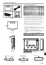
2.  Installing the FTC2BR unit ........................................................................3

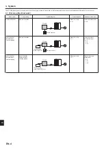
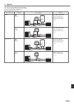
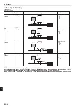
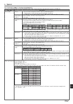
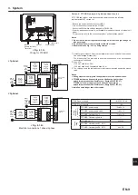
3. System ......................................................................................................4

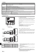
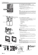
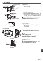
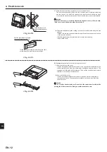
4.  Electrical work .........................................................................................10

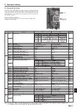
5.  Dip switch setting ....................................................................................17

6.  Before test run .........................................................................................22

7.  Remote controller operation ....................................................................23

8. Troubleshooting .......................................................................................29

9.  Supplementary information .....................................................................31

Local application factors ................................................................................32

1. Safety precautions

“FTC2BR” is the abbreviation of “Flow Temperature Controller 2BR”,  which is described as “FTC2BR” in this manual.

Mitsubishi Electric is not responsible for the failure of locally supplied parts.

1.5.  Electric booster and Immersion heaters

 Warning:

•   FTC2BR has signal outputs for booster heaters however it can not isolate 

power to them in the event of overheating. All electrical heaters used on 

the water circuit must have

  a) A thermostat to prevent overheating

  b) A non-self resetting thermal mechanism to prevent overheating

en

Содержание PAC-IF033B-E

Страница 1: ...English FLOW TEMP CONTROLLER 2BR Cased PAC IF033B E INSTALLATION MANUAL For safe and correct use read this manual thoroughly before installing the FTC2BR unit FOR INSTALLER ...

Страница 2: ...an unusual environment If the FTC2BR unit is installed or exposed to steam volatile oil including machine oil or sulfuric gas or exposed to briny air the internal parts can be damaged Do not install the unit where combustible gases may leak be produced flow or accumulate If combustible gas accumulates around the unit it may cause fire or explosion When installing the unit in a hospital or in a bui...

Страница 3: ... the weight and vibration of the unit Avoid locations where the unit is exposed to oil steam or sulfuric gas Do not install in location that is hot or humid for long periods of time Fig 2 1 1 22 11 5 Unit mm 11 5 5 12 10 200 313 3 ELECTRIC WIRE INLET When installed on a wall Lower side 278 336 69 TB143 TB141 TB142 C C C C TB6 Fig 2 3 4 Top Bottom Pull the cover to the front and remove it Slide the...

Страница 4: ...1 4 4 2 External input and analog input Outdoor unit only Local controller External input Analog signal Local controller 4 1 Power supplies Operation mode input Outdoor unit FTC2BR Remote controller Outdoor unit FTC2BR Remote controller Local controller ON OFF MODE Local controller ON OFF MODE Temp Outdoor unit FTC2BR The FTC2BR is designed for use with a number of heat pump systems Please refer t...

Страница 5: ...Return water temp Packaged type 4 3 4 3 4 3 4 3 Thermistor Outdoor unit FTC2BR DHW tank THW5 Heat exchanger Outdoor unit FTC2BR Heat exchanger THW1 THW1 THW1 THW1 Outdoor unit FTC2BR DHW tank THW5 Heat emitter Heat emitter Heat emitter Heat emitter TH2 THW2 THW2 THW2 THW2 Heat exchanger Outdoor unit FTC2BR TH2 Heat exchanger Present Present Absent Absent Outdoor unit type DHW tank 3 2 Second step ...

Страница 6: ...t Absent 4 4 4 4 3 4 4 4 4 3 4 4 4 4 3 3 3 Third step Heater setting Immersion heater Booster heater position Note When the booster heater is positioned for heating only flow water temp thermistor THW1 is not able to detect the outlet water temperature of circulation water during DHW or legionella prevention mode To determine more accurately if the heater is ON with DHW or legionella prevention mo...

Страница 7: ...y Connect the surge absorber according to the load at site Separate power for heater Install an earth leakage circuit breaker for heater separate from control power Heater capacity Breaker wiring recommended Description Power supply Capacity Breaker Wiring Immersion heater DHW tank N 230V 50Hz 3 kW 16 A 2 5 mm When installing an immersion heater with the capacity of bigger than shown above select ...

Страница 8: ...echnician Failure to comply with this could lead to electrocution fire and death It will also invalidate product warranty All wiring should be according to national wiring regulations Connections should be made to the terminals indicated in the following figures de pending on the phase When the wires are wired to adjacent terminals use ring terminals and insu late the wires Option 1 FTC2BR powered...

Страница 9: ...r units have separate power supplies the following requirements MUST carried out Remove the short circuited connector CNS2 Turn on the outdoor unit before the FTC2BR Outdoor unit DIP switch settings changed to SW8 3 ON Power by independent source is not available for particular models of outdoor unit model For more detail refer to the connecting outdoor unit installation manual Notes 1 Do not run ...

Страница 10: ... the remote controller either directly on the wall or in the switch box 2 Prepare the following items in the field Double switch box Thin metal conduit Locknut and bushing Cable cover Wall plug 2 Drill an installation hole in the wall Installation using a switch box Drill a hole in the wall for the switch box and install the switch box in the hole Fit the conduit tube into the switch box Direct wa...

Страница 11: ... remote controller do not overtighten the screws and make an additional installation hole s 6 Cut out the cable access hole Direct wall installation Cut out the knockout hole indicated with grey in Fig 4 2 7 in the cosmetic cover by knife or nipper Thread the remote controller cable from the slot behind the back cover through this access hole 7 Plug the lead wire cable into the front cover Plug th...

Страница 12: ... along the wall surface Thread the remote controller cable through the cable access hole at the top of the remote controller Seal the gap between the cable and the access hole with putty Use a cable cover Disassembling the front cover and the cosmetic cover 1 Remove the cosmetic cover Insert a flat head screwdriver into either of two open slots at the bottom of the remote controller and move the s...

Страница 13: ...it Thermistor position Place THW1 on water piping water outlet side after booster heater and THW2 on the water inlet side It is recommended to protect the thermistor with heat insulating materials so as not to be affected by ambient temperature Note Be sure to attach THW1 where it correctly detects Flow temp water oulet side 4 3 3 Connecting the actual DHW tank thermistor THW5 cable Connect the TH...

Страница 14: ...booster heater piping SPLIT type without a refrigerant water HEX inside 1 Refrigerant water HEX DHW tank temperature Water OUTLET side after booster heater Water piping Water INLET side THW1 TH2 THW5 THW2 1 FTC2BR FTC2BR FTC2BR FTC2BR Outdoor unit SPLIT type outdoor unit with booster heater THW1 TH2 THW2 THW5 Not necessary 1 Refrigerant Refrigerant LIQUID side piping SPLIT type without a refrigera...

Страница 15: ...DHW mode Input signal Pulse Pulse specifications ON short OFF open When SW1 1 or SW1 2 or both are ON the mode is switched into DHW mode 4 4 2 External inputs Analog signal 4 20mA 1 5V 0 10V Connect the transmission cables to No 11 and 12 on the terminal block TB143 No 11 on the terminal block TB143 Plus side No 12 on the terminal block TB143 Minus side Reference side Wiring specification and fiel...

Страница 16: ...ontactor or relay for immersion heater Immersion heater Direct cut off thermostat OUT4 TB141 7 8 Earth leakage circuit breaker for booster heater Contactor or relay for protecting booster heater Indirect cut off thermostat Cut off thermostat Contactor or relay for booster heater 1 OUT2 TB141 3 4 OUT3 TB141 5 6 Contactor or relay for protecting Booster heater1 Booster heater2 OUT3 TB141 5 6 Wiring ...

Страница 17: ... Heating mode OFF Heating circuit ON DHW circuit OFF SW3 2 Water circulation pump manual operation OFF ON OFF SW3 3 3 way valve manual operation OFF ON OFF SW3 4 Room thermostat input Ana IN1 logic change Operation stop at thermostat short Operation stop at thermostat open OFF SW3 5 Comp OFF for mode change DHW Heating Inactive Active OFF SW3 6 Flow switch input IN3 logic change Failure detection ...

Страница 18: ...mitter DHW tank THW5 THW1 THW2 Immersion heater 3 way valve OFF WITH DHW tank OFF WITHOUT immersion heater ON For heating only Booster heater Heat emitter DHW tank THW5 THW1 THW2 3 way valve OFF WITH DHW tank ON WITH immersion heater ON For heating only Booster heater Heat emitter DHW tank THW5 THW1 THW2 Immersion heater 3 way valve ON WITHOUT DHW tank Booster heater Heat emitter THW1 THW2 Summary...

Страница 19: ...0mA OFF 0 2mA Set Dip SW 1 7 to set activate or deactivate cooing mode Dip SW 1 7 Setting OFF Inactive ON Active When Dip SW 1 7 is OFF cooling mode is not available Set Dip SW 1 8 to set activate or deactivate automatic change over mode DHW Heating Dip SW 1 8 Setting OFF Active ON Inactive Set Dip SW 1 9 to set activate or deactivate automatic change over mode DHW Cooling Dip SW 1 9 Setting OFF A...

Страница 20: ...utput separate signals for each operation mode This can be realised by using a schedule timer and relays SW1 1 ON SW1 2 OFF SW1 8 OFF SW1 9 OFF or SW1 1 ON SW1 2 OFF SW1 8 ON SW1 9 ON Example 4 Only a Local controller is used for system control The system operates in the same way as Example 3 except that the target temperatures for each mode must also be inputted via the analogue signal from the l...

Страница 21: ...0 minutes consecutive operation NOTE Even if you forget to reset the Dip SW settings above the normal operation mode can be recovered automatically in 60 minutes 5 6 Emergency mode The emergency mode is available when a failure on the outdoor unit of the heat pump or a communication error occurs This mode uses booster heater or immersion heater as a heat source and automat ically controls between ...

Страница 22: ...h pressure protection Flow rate of the heating circuit may be reduced Check water circuit Plate heat exchanger may be clogged Check the plate heat exchanger Outdoor unit failure Refer to outdoor unit service manual LF Light down Light down Flow sensor failure Check flow sensor cable for damage or loose connections P1 Blink Light down Thermistor Flow water temp THW1 failure Check resistance across ...

Страница 23: ...e system is switched off or the power supply is disconnected the water circuit protection functions will NOT operate Please beware that with out these safety functions enabled the water circuit may potentially become exposed to damage Main screen icons No Item Icon Description 1 Operation prohi bition ON OFF Mode Set temperature 2 Operation lock Displayed when the buttons are locked 3 Holiday mode...

Страница 24: ...e Time Language C F Temp display Contact number Time display Main Sub Service Password protected Function setting Restriction Operation lock Mode skip Temp range DHW Heating Cooling Temp offset setting DHW Heating Cooling Temp Analog signal DHW Heating Cooling Self check Running information Error history Password protection Remote controller check 7 Remote controller operation User and installer I...

Страница 25: ...g Installer level Compensation curve Initial settings Service Password protected Use the F2 and F3 buttons to move between the icons The highlighted icon will appear as a larger version in the cen tre of the screen Press CONFIRM to select and edit the highlighted mode Water temp setting Set the initial value of the set water temperature for following modes DHW mode Heating mode Cooling mode Holida...

Страница 26: ...4 to highlight either 1 2 3 see below 4 Press CONFIRM Note Changes can ONLY be made to Mode 1 Mode 1 Setting number meanings 1 Power failure automatic recovery NOT available 2 Power failure automatic recovery AVAILABLE Approx 4 minute delay after power is restored 3 No function Restriction Operation lock Restrict the operation of switching ON OFF changing the operation mode and the set temperature...

Страница 27: ...press F3 button Yes Password protection Password protection is available to prevent unauthorised access to the service menu by untrained persons 1 When password input screen is displayed use buttons F1 and F2 to move left and right between the four digits F3 to lower the selected digit by 1 and F4 to increase the selected digit by 1 2 When you have input your password press CONFIRM 3 The password ...

Страница 28: ...PM hh mm hh mm Service Restriction Operation lock none Mode Temp All none Mode skip DHW Used Not used Skipped Used Heating Used Not used Skipped Used Heating Eco Used Not used Skipped Used Cooling Used Not used Skipped Used Holiday Used Not used Skipped Used Temp range DHW 20 60 C 20 60 C Heating 20 60 C 20 60 C Cooling 5 25 C 5 25 C Temp offset setting DHW Heating 15 15 C 0 Cooling 15 15 C 0 Temp...

Страница 29: ...re 4 Check the FTC2BR control board Check the fuse on FTC2BR control board Check for faulty wiring If no problem found with the wiring the FTC2BR control board is faulty FTC2BR powered on independent source 1 FTC2BR is not supplied with 220V to 240V AC 1 Check the voltage across the L and N terminals on the indoor power supply terminal block When the voltage is not 220 to 240V AC check for faulty ...

Страница 30: ... pressure relief valve to check for foreign objects in it If the problem is not still solved replace the pressure relief valve with a new one 2 If intermittent expansion vessel charge may have reduced bladder perished 2 Check pressure in expansion vessel Recharge to 1 bar if necessary If bladder perished replace expansion vessel with a new one 15 Water discharges from pressure relief valve Sanitar...

Страница 31: ...t enter the signals IN1 IN2 IN4 IN5 IN6 IN7 IN8 for external inputs refer to 4 4 1 And if the system is set in Dip SW1 1 1 2 is OFF ON or ON ON pumpdown operation cannot be started Set Dip SW1 1 1 2 to OFF OFF or ON OFF For more details refer to Refrigerant collection in the outdoor unit instal lation manual or service manual en ...

Страница 32: ...of contamination per unit cubic content of heat transfer pipe is less than the following amount Example In case of 9 52 mm Residual water 0 6 mg m Residual oil 0 5 mg m Solid foreign object 1 8 mg m Thermistor position Refer to 4 3 Notes Install the hydraulic filter at the water inlet pipework Inlet water temperature of heat exchanger should be within the range 5 C 55 C Water quality should be to ...

Страница 33: ... the following descriptions does NOT mean the guarantee of safety or the conformity with IEC 60335 2 40 Edition 6 0 Other requirements Requirements for marking e g flame symbol and information in the manual shall be satisfied Requirements for constructions e g location of the refrigerant detection sensor shall be satisfied 2 Additional Requirements for using R32 Refrigerant a Flow sensor Outdoor u...

Страница 34: ...isku mieszkalnym handlowym i lekko uprzemysłowionym erklærer hermed som sitt ansvar ene og alene at komponentene i varmesystemet som beskrives nedenfor og som er beregnet for bruk i bolig forretnings og lettindustrimiljøer vakuuttaa täten asiasta yksin vastuussa että alla kuvatut lämmitysjärjestelmän osat jotka on tarkoitettu käytettäviksi asuin toimisto ja kevyen teollisuuden ympäristöissä tímto ...

Страница 35: ......

Страница 36: ...OFFICE TOKYO BUILDING 2 7 3 MARUNOUCHI CHIYODA KU TOKYO 100 8310 JAPAN BH79D852H01 Printed in Japan Please be sure to put the contact address telephone number on this manual before handing it to the customer ...

Отзывы: