


EN-22
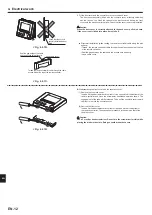
6. Before test run
6.1. Check
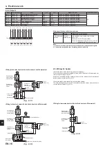
After completing installation and the wiring and piping of the local application and
outdoor units, check for refrigerant leakage, looseness in the power supply or con-
trol wiring, wrong polarity, and power cable is securely connected.
Use a 500-volt megohmmeter to check that the resistance between the power sup-
ply terminals and ground is at least 1.0MΩ.
Warning:
Do not use the system if the insulation resistance is less than 1.0MΩ.
Caution:
Do not carry out this test on the control wiring (low voltage circuit) termi-
nals.
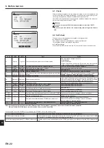
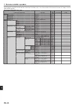
6.2. Self-check
When an error occurs when power is applied or during operation
■ Indication of error details
The code, unit, address, and telephone number are displayed.
The telephone number is displayed if registered.
■ Resetting the error
Press the F4 (RESET) button, and the F3 (Yes) button to reset the current error.
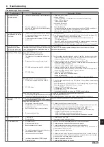
Code
LED4
LED5
Error
Action
L3
Light up
Light up
Circulation water temperature overheat protection
Flow rate may be reduced check for;
• Water leakage
• Strainer blockage
• Water circulation pump function (Error code may display during
filling of primary circuit, complete filling and reset error code.)
L4
Blink
Blink
DHW tank water temperature overheat protection
Check the immersion heater and it’s contactor.
L5
Blink
Light down Thermistor (Return water temp.) (THW2)
Check resistance across the thermistor.
L6
Light up
Blink
Circulation water freeze protection
See Action for L3.
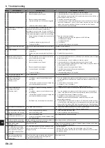
L8
Light down
Light up
Heating operation error
Re-attach any thermistors that have become dislodged.
L9
Light up
Light down Low primary circuit flow rate detected by flow switch (flow
switch)
See Action for L3. If the flow switch itself does not work, replace it.
Caution: The pump valves may be hot, please take care.
LA
Light down Light down Pressure sensor failure
Check pressure sensor cable for damage or loose connections.
LB
Light down Light down High pressure protection
• Flow rate of the heating circuit may be reduced. Check water circuit.
• Plate heat exchanger may be clogged. Check the plate heat exchanger.
• Outdoor unit failure. Refer to outdoor unit service manual.
LF
Light down Light down Flow sensor failure
Check flow sensor cable for damage or loose connections.
P1
Blink
Light down Thermistor (Flow water temp.) (THW1) failure
Check resistance across the thermistor.
P2
Light down
Blink
Thermistor (Ref. liquid temp.) (TH2) failure
Check resistance across the thermistor.
P6
Blink
Light up
Anti-freeze protection of plate heat exchanger
See Action for L3.
Check for correct amount of refrigerant.
P9
Blink
Light down Thermistor (Tank water temp.) (THW5) failure
Check resistance across the thermistor.
E0, E3,
E4, E5
—
—
Communication failure between remote controller and FTC2BR Check connection cable for damage or loose connections.
E1, E2
—
—
Remote controller board error
Replace remote controller.
E6 - EF
—
—
Communication failure between FTC2BR and outdoor unit
Check that the outdoor unit has not been turned off.
Check connection cable for damage or loose connections.
Refer to outdoor unit service manual.
EE
—
—
Combination error between FTC2BR and outdoor unit
Check combination of FTC2BR and outdoor unit.
U*, F*
—
—
Outdoor unit failure
Refer to outdoor unit service manual.
Note: For the system using a local controller (External input: Contact signal), you cannot cancel an error with the remote controller.
When all of the IN4 to IN8 inputs are not received, the error will be cancelled.
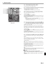
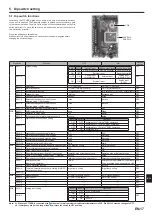
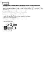
For description of each LED (LED1 to 3) provided on the FTC2BR, refer to the following table.
LED 1 (Power for microcomputer)
Indicates whether control power is supplied. Make sure that this LED is always lit.
LED 2 (Power for remote controller)
Indicates whether power is supplied to the remote controller. This LED lights only in the case of the FTC2BR
unit which is connected to the outdoor unit refrigerant address “0“.
LED 3 (Communication between FTC2BR and outdoor unit) Indicates state of communication between the FTC2BR and outdoor unit. Make sure that this LED is always blink-
ing.
en
Содержание PAC-IF033B-E
Страница 35: ......


