
EN-10
30
30
30
120
46
83.5
Wall
Bushing
Conduit tube
Locknut
Switch box
Seal the gap with putty.
Remote controller cable
Cosmetic cover and front cover
Back cover
10mm
6mm
Sheath
Front
Back
Thread the cable.
Completely thread the
unsheathed portion to the front.
The 2 inner wires must not be
seen on the back.
Connect the 2 inner wires to the
terminal block (non polarized).
Remote controller cable
Seal the gap with putty.
Thread the cable from behind
the remote controller.
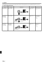
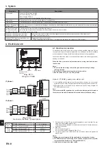
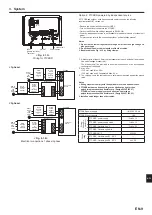
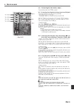
4.2. Connecting the remote controller
4.2.1. Connect the remote controller cable to FTC2BR
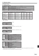
Connect the remote controller cable to 13 and 14 on the terminal block (TB143) on
the FTC2BR controller. <Fig. 4.2.1>
Wiring wire No. × size (mm²): 2 × 0.3 (non polar)
The 5 m wire is attached as an accessory. Max. 500 m
Wiring size must comply with the applicable local and national codes.
Circuit rating: 12V DC
Circuit rating is NOT always against the ground.
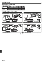
Notes:
Wiring for remote controller cable shall be (5 cm or more) apart from power
source wiring so that it is not infl uenced by electric noise from power source
wiring. (Do not insert remote controller cable and power source wiring in the
same conduit.) (Refer to Fig. 4.1.1)
When wiring to TB143, use the ring type terminals and insulate them from the
cables of adjoining terminals.
<Fig. 4.2.1>
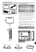
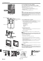
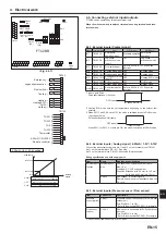
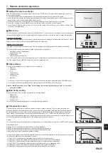
4.2.2. Installing the remote controller
1. The remote controller can be installed either in the switch box or directly on the
wall. Perform the installation properly according to the method.
(1) Secure clearances shown in <Fig. 4.2.2> regardless of whether installing the
remote controller either directly on the wall or in the switch box.
(2) Prepare the following items in the fi eld.
Double switch box
Thin metal conduit
Locknut and bushing
Cable cover
Wall plug
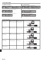
2. Drill an installation hole in the wall.
■ Installation using a switch box
• Drill a hole in the wall for the switch box, and install the switch box in the hole.
• Fit the conduit tube into the switch box.
■ Direct wall installation
• Drill a cable access hole and thread the remote controller cable through it.
Caution:
To prevent entry of dew, water, and insects, seal the gap between the cable
and the hole through which the cable is threaded with putty. Otherwise, elec-
tric shock, fi re, or failure may result.
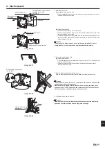
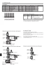
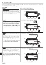
3. Have the remote controller ready.
Remove the back cover from the remote controller.
4. Connect the remote controller cable to the terminal block on the back cover.
Modify the remote controller cable as shown in <Fig. 4.2.5>, and thread the ca-
ble from behind the back cover.
Completely thread the cable to the front so that the unsheathed part of the cable
cannot be seen behind the back cover.
Connect the remote controller cable to the terminal block on the back cover.
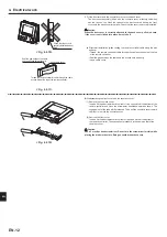
■ Direct wall installation
• Seal the gap between the cable and the hole through which the cable is
threaded.
Caution
To prevent electric shock or failure, keep the sheath ends or any other
foreign objects out of the terminal block.
Do not use ring terminals to connect the wires to the terminal block on the
back cover. The terminals will come in contact with the control board and the
cosmetic cover, which will result in failure.
<Fig. 4.2.2>
<Fig. 4.2.3>
<Fig. 4.2.4>
<Fig. 4.2.5>
Required clearances
surrounding the remote
controller
Remote controller profi le
Installation pitch
TB143 RC
4. Electrical work
en
Содержание PAC-IF033B-E
Страница 35: ......


