
EN-15
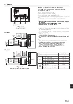
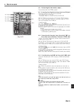
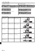
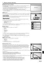
4.4. Connecting external inputs/outputs
FTC2BR can be operated by following external input.
When the wires are wired to adjacent terminals use ring terminals and insu-
late the wires.
FTC2BR
TB142
TB141
1
5
SW3
SW4
TB143
CN21
(YE)
CN401
(WH)
CNS2
(RD)
1 3
CNW5
SW6
(WH)
CN1A
(WH)
CN105
(RD)
8
1
CN100
(WH)
LED5
LED2
LED1
SW2
1
1
5
10
1
10
1
10
SW1
LED4
LED3
1
1
2
2
1 3
1
4
1
4
1
4
CNW12
(RD)
2 4 6 8 10 12 14
1 3 5 7 9 11 13
2 4 6 8 10 12 14
1 3 5 7 9 11 13
TB6
S1 S2 S3
L N
2
4
6
8
10
12
14
1
3
5
7
9
11
13
<Fig. 4.4.1>
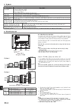
4. Electrical work
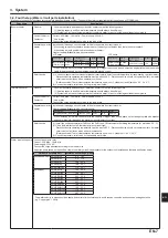
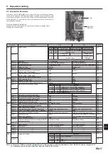
4.4.1. External inputs (Contact signal)
Name Terminal block
Item
OFF(Open)
ON(Short)
IN1
TB142 1-2
Emergency
operation input
Srandard operation Emergency
operation
IN2
TB142 3-4
Legionella
prevention mode
input *1
OFF
Legionella
prevention mode
IN3
TB142 5-6
Flow switch input
Refer to SW3-6 in <5.1. Dip switch
function>
IN4
TB142 7-8
Cooling mode input OFF
Cooling mode
IN5
TB142 10-11 Heating mode input OFF
Heating mode
IN6
TB142 10-12 Heating ECO mode
input *2
OFF
Heating ECO mode
IN7
TB142 10-13 DHW mode input *3 OFF
DHW mode
IN8
TB142 10-14 Holiday mode input OFF
Holiday mode
Ana.IN1 TB143 9-10 Room thermostat
input
Refer to SW3-4 in <5.1. Dip switch
function>
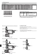
*1 Input signal: Pulse
Pulse specifications: ON (short)
OFF (open)
*2 Heating ECO mode sets the set temperature depending on the outdoor tem-
perature.
*3 When SW1-1 and SW1-2 are OFF, the mode is switched into auto DHW mode.
Input signal: Pulse
Pulse specifications: ON (short)
OFF (open)
When SW1-1 or SW1-2, or both are ON, the mode is switched into DHW mode.
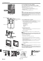
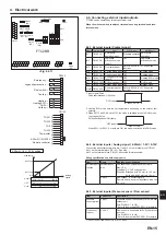
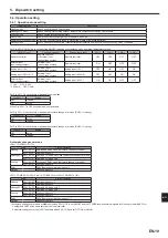
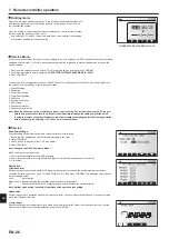
4.4.2.
External inputs ( Analog signal ) 4-20mA / 1-5V / 0-10V
Connect the transmission cables to No.11 and 12 on the terminal block (TB143).
No.11 on the terminal block (TB143) : Plus side
No.12 on the terminal block (TB143) : Minus side (Reference side)
Wiring specification and field supply parts
Item
Name
Model and specifications
External inputs
function
External inputs
wire
Use sheathed vinyl coated cord or cable.
Max. 10 m
Wire type: CV, CVS or equivalent
Wire size: Stranded wire 0.5 mm² to 1.25 mm²
Solid wire: ø0.65 mm to ø1.2 mm
Switch
Non-voltage “a” contact signals
Remote switch: minimum applicable load 12V
DC, 1mA
4.4.3.
External inputs (Pressure sensor / Flow sensor)
Item
Connector
Description
Pressure
sensor (option)
CN401
Pressure sensor is necessary for SUZ-SWM
outdoor unit.
Turn Dip SW 4-1 to ON.
* Refer to the manual of PAC-PS01-E for details.
Flow sensor
(option)
CN1A *1
Flow sensor is necessary for PUZ-(H)WM out-
door unit.
Turn Dip SW 4-2 to ON.
* Refer to the manual of PAC-FS01-E for details.
6
5
2
1
4
3
TB143
4-20mA/1-5V/0-10V
12
11 +
–
8
7
10
9
14
13
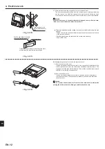
(
Remote controller
(
THW1
THW2
THW5
TH2
Thermostat
(
(
(
(
(
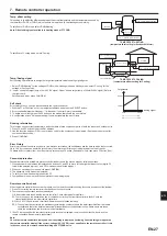
0mA -- 4mA --------------- 20mA
0V-------1V------------------- 5V
0V------------------10V
No.1 Temp.
Stop
4-20mA
Refer to the section 10 for details about No1, 2 Temp.
1-5V
0-10V
No.2 Temp.
Flow temp.
Analog
signal
4-20mA / 1-5V / 0-10V setting
*1 Do not connect flow sensor of CN1A to CNW12.
en
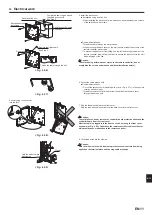
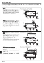
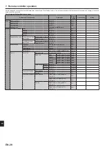
TB142
11
10
12
13
14
HeatingECO
→
Holiday
→
DHW
→
Heating
→
6
5
7
8
9
2
1
3
4
Flow switch
→
Cooling
Emergency
Legionella prevention
→
→
→
200ms or more
200ms or more
Содержание PAC-IF033B-E
Страница 35: ......


