background image

11. DISPLAY AND OPERATION SETTINGS (GOT SET UP)

11.2 Operation Setting (Settings Regarding Operation)

11 - 9

9

UTILIT

Y

 FUNCTION

10

C

O

MM

UNICA

TIO

N


IN

TE

RF

AC

E S

ETTING


(CO

M

MUN

ICA

TION

 S

ETTIN

G

)

11

DI

SPL

A

Y

 AN

D


OPERA

T

ION S

E

TTINGS


(G

OT SE

T UP)

12

C

LOC

K SET

TI

N

GS 

AN

D


BA

TT

ER

Y ST

AT

U

S D

IS

PL

AY


(T

IM

E SET

TI

N

G

 A

N

D

 D

ISPL

AY)

13

FILE

 D

ISP

LA

Y A

N

C

O

PY

 (P

RO

GR

AM

/D

A

TA 

CONTR

O

L

)

14

GO

T

 SE

LF

 CHE

CK


(DEB

UG AND 

S

E

LF 

CHECK)

15

CLEA

NING DISPL

A

Y


SE

CT

ION (CLE

AN)

16

INST

ALLA

TION OF 

C

O

REOS, BOOT

OS 

A

N

ST

AN

DA

RD

 MO

NI

T

O

OS

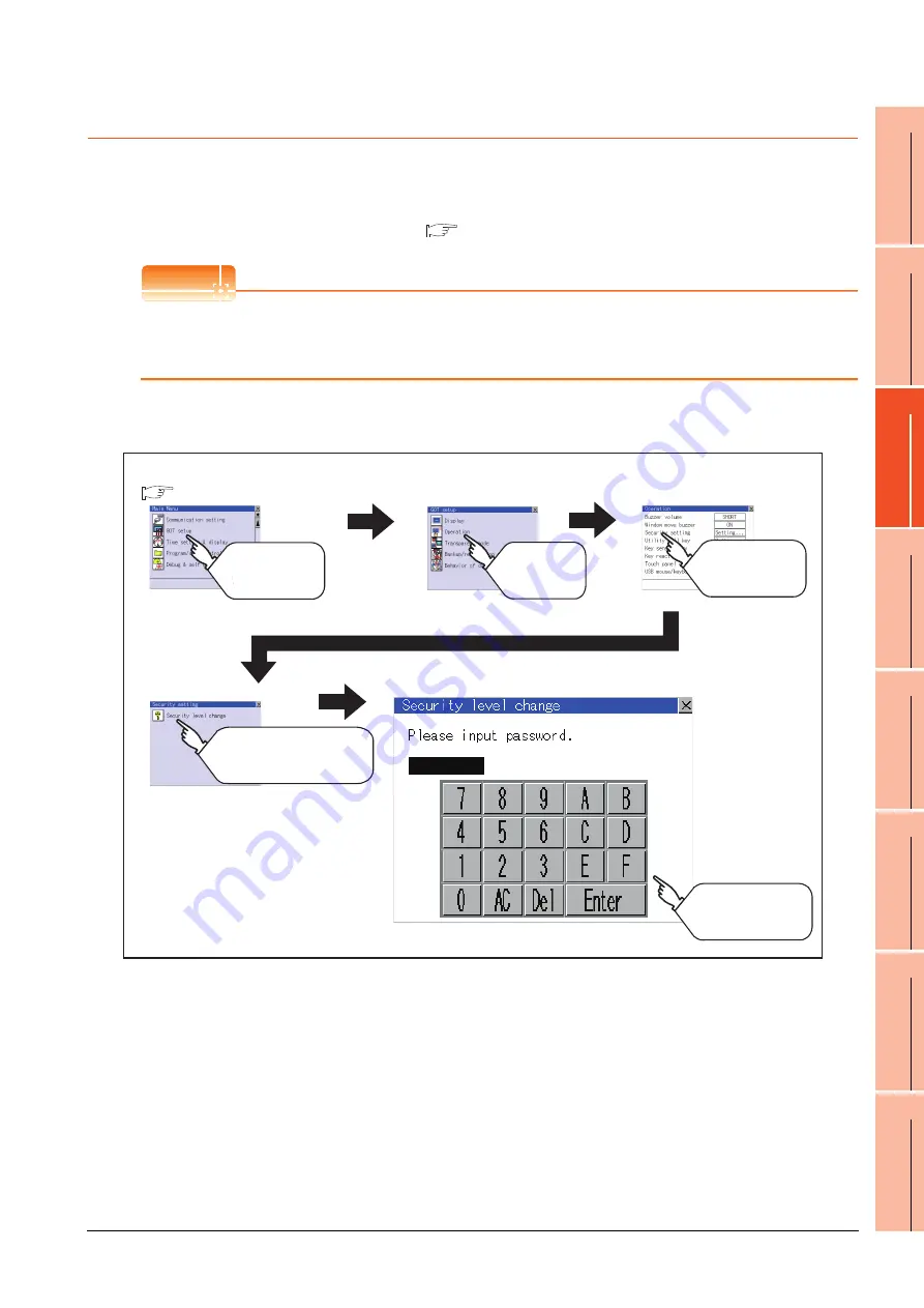
11.2.4 Security level change

Security level change functions

Changes the security level to the same security level set by each object or screen switch.
To change the security level, input the password of the security level which is set in GT Designer3.

POINT

POINT

POINT

Restrictions on screen display
The security level change screen cannot be displayed when project data do not exist in GOT.
Change the security level after downloading the project data to GOT.

Display operation of Security level change

Security level setting, Password setting................

GT Designer3 Version1 Screen Design Manual (Fundamentals)

GOT setup

Operation

Touch
[GOT setup]

Touch
[Operation]

Main menu

Security level change

Touch
[Security setting]

Security setting

Touch
[Security level change]

Input the password of
the security level which
is set in Drawing software

(

 9.3 Utility Display)

Содержание Got 1000

Страница 1: ......

Страница 2: ......

Страница 3: ...ve A system where the GOT is used should be configured to perform any significant operation to the system by using the switches of a device other than the GOT on the assumption that a GOT communication fault will occur Not doing so can cause an accident due to false output or malfunction Do not use the GOT as the warning device that may cause a serious accident An independent and redundant hardwar...

Страница 4: ...material as a pen or driver Doing so can result in a damage or failure of the display section When the GOT is connected to the Ethernet network the available IP address is restricted according to the system configuration When multiple GOTs are connected to the Ethernet network Do not set the IP address 192 168 0 18 for the GOTs and the controllers in the network When a single GOT is connected to t...

Страница 5: ... removing a SD card into from the GOT turn the SD card access switch off in advance Failure to do so may corrupt data within the SD card When removing a SD card from the GOT make sure to support the SD card by hand as it may pop out Failure to do so may cause the SD card to drop from the GOT and break When installing a USB memory to the GOT make sure to install the USB memory to the USB interface ...

Страница 6: ...lamped Not doing so can cause the unit or cable to be damaged due to the dangling motion or accidental pulling of the cables or can cause a malfunction due to a cable connection fault When unplugging the cable connected to the unit do not hold and pull the cable portion Doing so can cause the unit or cable to be damaged or can cause a malfunction due to a cable connection fault Plug the communicat...

Страница 7: ... Doing so can cause a failure malfunction injury or fire Do not touch the conductive and electronic parts of the unit directly Doing so can cause a unit malfunction or failure Do not drop or apply strong impact to the unit Doing so may damage the unit Do not drop or give an impact to the battery mounted to the unit Doing so may damage the battery causing the battery fluid to leak inside the batter...

Страница 8: ...y be activated This may cause an unexpected operation due to incorrect output or malfunction CAUTION When transporting lithium batteries make sure to treat them based on the transport regulations For details on models subject to restrictions refer to the User s Manual for the GOT you are using Before transporting the GOT turn the GOT power on and check that the battery voltage status is normal on ...

Страница 9: ...s 3 2 3 3 Power Supply Specifications 3 3 4 PARTS NAME 4 1 Front Panel 4 1 4 2 Back Panel 4 2 4 3 Rear Face 4 3 5 UL cUL STANDARDS AND EMC DIRECTIVE 5 1 UL cUL Standards 5 1 5 2 EMC Directive 5 1 5 2 1 Requirements to Meet EMC Directive 5 2 5 2 2 EMC Directive Compliant System Configuration 5 4 5 2 3 Precautions for Wiring Connecting the EMC Directive Compliant Product 5 5 INTRODUCTION Thank you f...

Страница 10: ...ing and removing procedures of the USB memory 8 3 8 3 Battery 8 4 8 3 1 Applicable battery 8 4 8 3 2 Battery specifications 8 4 8 3 3 Battery replacement procedure 8 5 8 4 Protective Sheet 8 6 8 4 1 Applicable protective sheet 8 6 8 4 2 Installing procedure 8 6 8 5 Protective Cover for Oil 8 7 8 5 1 Applicable protective cover for oil 8 7 8 5 2 Installing procedure 8 7 8 6 USB Environmental Protec...

Страница 11: ...ommunication setting operation 10 4 10 2 Communication Detail Setting 10 8 10 2 1 Communication detail setting functions 10 8 10 2 2 Display operation of Communication Detail setting 10 8 10 2 3 Display contents of Communication Detail setting 10 10 10 3 Ethernet Setting 10 15 10 3 1 Ethernet setting functions 10 15 10 3 2 Display operation of Ethernet setting 10 15 10 3 3 Display contents of Ethe...

Страница 12: ... Logging information 13 53 13 2 7 Memory card format 13 63 13 2 8 Memory information 13 65 13 2 9 USB device status display 13 66 13 2 10 SRAM control 13 68 13 2 11 GOT data package acquisition 13 73 13 2 12 Operator information management 13 74 14 GOT SELF CHECK DEBUG AND SELF CHECK 14 1 Debug 14 1 14 1 1 System monitor 14 1 14 1 2 A list editor 14 1 14 1 3 FX list editor 14 1 14 1 4 Backup resto...

Страница 13: ...7 2 17 2 Periodic Inspection 17 2 17 3 Cleaning Method 17 3 17 4 Battery Voltage Low Detection and Battery Replacement 17 4 17 5 Backlight Shutoff Detection 17 7 17 5 1 Backlight shutoff detection and external alarm 17 7 18 TROUBLESHOOTING 18 1 GOT Restoration Sheet 18 1 18 2 Error Message and System Alarm 18 11 18 2 1 Error contents display 18 11 18 2 2 List of error message system alarm 18 13 AP...

Страница 14: ...A 12 ...

Страница 15: ...MC5 GT Simulator3 Version1 Operating Manual for GT Works3 Stored in CD ROM SH 080861ENG 1D7MB1 GOT1000 Series User s Manual Extended Functions Option Functions for GT Works3 Stored in CD ROM SH 080863ENG 1D7MB3 Obtaining the specifications and operation methods of GT Designer3 GT Designer3 Version1 Screen Design Manual Fundamentals 1 2 2 2 Setting available functions on GT Designer3 Creating a scr...

Страница 16: ...ining information of peripheral devices applicable to the GOT GOT1000 Series Connection Manual Microcomputer MODBUS Products Peripherals for GT Works3 Connecting peripheral devices including a barcode reader to the GOT Writing data to the GOT GT Designer3 Version1 Screen Design Manual Fundamentals 1 2 2 2 Reading data from the GOT Verifying a editing project to a GOT project Configuring the extend...

Страница 17: ...reviation of GT1562 VNBA GT1562 VNBD GT155 GT1555 V Abbreviation of GT1555 VTBD GT1555 Q Abbreviation of GT1555 QTBD GT1555 QSBD GT1550 Q Abbreviation of GT1550 QLBD GT15 Abbreviation of GT1595 GT1585 GT157 GT156 GT155 GT145 GT1455 Q Abbreviation of GT1455 QTBDE GT1455 QTBD GT1450 Q Abbreviation of GT1450 QMBDE GT1450 QMBD 1450 QLBDE GT1450 QLBD GT14 Abbreviation of GT1455 Q GT1450 Q GT1275 GT1275...

Страница 18: ... 25P Ethernet communication unit GT15 J71E71 100 MELSECNET H communication unit GT15 J71LP23 25 GT15 J71BR13 MELSECNET 10 communication unit GT15 75J71LP23 Z 1 GT15 75J71BR13 Z 2 CC Link IE Controller Network communication unit GT15 J71GP23 SX CC Link IE Field Network communication unit GT15 J71GF13 T2 CC Link communication unit GT15 J61BT13 GT15 75J61BT13 Z 3 Interface converter unit GT15 75IF900...

Страница 19: ... GT14 50PSGB GT14 50PSCW GT14 50PSGW For GT12 GT11 70PSCB GT11 65PSCB For GT11 GT11 50PSCB GT11 50PSGB GT11 50PSCW GT11 50PSGW GT11H 50PSC For GT10 GT10 50PSCB GT10 50PSGB GT10 50PSCW GT10 50PSGW GT10 40PSCB GT10 40PSGB GT10 40PSCW GT10 40PSGW GT10 30PSCB GT10 30PSGB GT10 30PSCW GT10 30PSGW GT10 20PSCB GT10 20PSGB GT10 20PSCW GT10 20PSGW Protective cover for oil GT05 90PCO GT05 80PCO GT05 70PCO GT...

Страница 20: ... later versions GX Developer Abbreviation of SW D5C GPPW E EV SW D5F GPPW E type software package GX LogViewer Abbreviation of SW DNN VIEWER E type software package PX Developer Abbreviation of SW D5C FBDQ E type FBD software package for process control MT Works2 Abbreviation of motion controller engineering environment MELSOFT MT Works2 SW DNC MTW2 E MT Developer Abbreviation of SW RNC GSV type i...

Страница 21: ... SCHNEIDER Abbreviation of Schneider Electric SA SICK Abbreviation of SICK AG SIEMENS Abbreviation of Siemens AG RKC Abbreviation of RKC INSTRUMENT INC HIRATA Abbreviation of Hirata Corporation MURATEC Abbreviation of Muratec products manufactured by Muratec Automation Co Ltd PLC Abbreviation of programmable controller Control equipment Generic term for control equipment manufactured by each corpo...

Страница 22: ... 9 2 0 Refers to the information required Refers to information useful for operation Indicates the setting items displayed on the software and GOT screen Refers to a button displayed on the computer screen or the GOT screen or a key of the computer keyboard Indicates the location of related content Indicates the operation procedure Perform procedures in numerical order ...

Страница 23: ... is a screen drawn by drawing software The objects Touch switch Lamp display Comment display and Numeric display can be arbitrarily arranged on the display Moreover multiple screens created within drawing software can be individually selected or overlapped for the display For details refer to the following GT Designer3 Version1 Screen Design Manual 2 Utility Screen The utility screen is a factory ...

Страница 24: ...Also compatible with digital screen displays with 65536 colors BMP etc In the monochrome display 16 scales are used to improve the display High speed monitoring through high speed communication at maximum of 115 2kbps High speed display and high speed touch switch response The operation performance is improved by the analog touch panel 3 More efficient GOT operations including screen design startu...

Страница 25: ...reen Design Manual Functions Wire for the GOT power supply and the controller 7 WIRING Refer to GOT1000 Series Connection Manual for GT Works3 Wire for the controller power supply and I O Controller manuals Turn on the power of GOT and controller Install the OS to GOT 16 INSTALLATION OF COREOS BOOTOS AND STANDARD MONITOR OS Refer to GT Designer3 Version1 Screen Design Manual Fundamentals Check tha...

Страница 26: ...1 4 1 OVERVIEW 1 1 Features ...

Страница 27: ... drop connection unit Battery SD card USB memory Protective sheet Bar code reader Commercially available RFID controller Commercially available USB mouse Commercially available USB keyboard Commercially available Personal computer Commercially available Printer Commercially available 1 RS 232 485 signal conversion adapter Refer to 8 3 Refer to 8 5 Refer to 8 7 Refer to 8 2 Refer to 8 1 Refer to 8 ...

Страница 28: ...ome black white DC24V memory size 9MB built in battery built in Ethernet interface GT1450 QMBD 5 7 320 240 dots TFT monochrome liquid crystal display monochrome black white DC24V memory size 9MB built in battery GT1450 QLBDE 5 7 320 240 dots STN monochrome liquid crystal display monochrome black white 24VDC memory size 9MB built in battery built in Ethernet interface GT1450 QLBD 5 7 320 240 dots S...

Страница 29: ...nnection cable GT01 C30R2 6P 3m For connecting GOT to QCPU FX expansion board connection FX special adaptor connection data transfer cable GT01 C30R2 9S 3m For connecting GOT to FXCPU expansion board D Sub 9pin For connecting GOT to FXCPU special adaptor D Sub 9pin FX special adaptor connection GT01 C30R2 25P 3m For connecting GOT to FXCPU special adaptor D Sub 25pin Computer link connection cable...

Страница 30: ... cable GT09 C30R20901 25P 3m For connecting GOT to Panasonic RS422 232C conversion adapter GT09 C30R20902 9P 3m For connecting GOT to the tool port or RS232C port of Panasonic PLC computer communication unit GT09 C30R20903 9P 3m For connecting GOT to the RS232C port of Panasonic PLC GT09 C30R20904 3C 3m For connecting GOT to the RS232C port of Panasonic PLC Product name Model name Cable length Con...

Страница 31: ...00R40302 6T 10m GT09 C200R40302 6T 20m GT09 C300R40302 6T 30m GT09 C30R40303 6T 3m For connecting GOT to YOKOGAWA temperature controller GT09 C100R40303 6T 10m GT09 C200R40303 6T 20m GT09 C300R40303 6T 30m GT09 C30R40304 6T 3m GT09 C100R40304 6T 10m GT09 C200R40304 6T 20m GT09 C300R40304 6T 30m RS 232 cable GT09 C30R20301 9P 3m For connecting GOT to YOKOGAWA CPU port D Sub 9pin conversion cable GT...

Страница 32: ...ing value advanced alarm advanced recipe logging hard copy and SRAM user area backups Product name Model name Contents Stand GT05 50STAND Stand for 5 7 Product name Model name Contents Protective cover for oil GT05 50PCO For 5 7 GOT Product name Model name Contents Protective sheet GT14 50PSCB 5 7 protective sheet Clear 5 sheets GT14 50PSGB Antiglare 5 sheets GT14 50PSCW Clear Frame white 5 sheets...

Страница 33: ...efer to List of valid devices applicable for GOT1000 series T10 0039 separately available or contact your local distributor RS 232 485 signal conversion adapter Sold separately Product name Model name Contents Bar code reader Commercially available bar code reader 4 RFID controller Commercially available RFID controller 4 Product name Model name Contents RS 232 485 signal conversion adapter GT14 R...

Страница 34: ...2 8 2 SYSTEM CONFIGURATION 2 2 System Equipment ...

Страница 35: ...used In pollution degree 2 only non conductive pollution occurs but temporary conductivity may be produced due to condensation Item Specifications Operating ambient temperature Display section 0 to 50 Other than display section 0 to 55 when horizontally installed 0 to 50 when vertically installed Storage ambient temperature 20 to 60 Operating ambient humidity 10 to 90 non condensing WBT 39 Storage...

Страница 36: ...get Clock data alarm history recipe data time action setting value advanced alarm advanced recipe logging hard copy and SRAM user area Life Approx 5 years Operating ambient temperature of 25 Built in interface RS 422 485 RS 422 485 1ch Transmission speed 115200 57600 38400 19200 9600 4800bps Connector shape D Sub 9pin Female Application For communicating with a controller Terminating resistor Open...

Страница 37: ... function prevents images from becoming permanently etched on the display screen and increases the backlight life 11 1 Display Setting 4 The touch panel is analog resistive film type If you touch the panel simultaneously in 2 points or more the switch that is located around the center of the touched point if any may operate Do not touch the panel in 2 points or more simultaneously Do not press the...

Страница 38: ...3 4 3 SPECIFICATIONS 3 3 Power Supply Specifications ...

Страница 39: ...en 2 Touch panel For touch switch operation on the utility screen and the user creation screen 3 POWER LED Lit in green Power is correctly supplied Lit in orange Screen saving Blinks in orange green Blown back light bulb Not lit Power is not supplied 4 Logo label Removable 5 USB interface USB interface for communicating with PC Device For OS installation project data download and FA transparent 6 ...

Страница 40: ...ED Lit SD card being accessed Not lit SD card is not accessed 8 SD card access switch Prohibits accessing the SD card removing the card from the GOT ON SD card being accessed SD card removal prohibited OFF SD card not accessed SD card removal possible 9 Battery GT11 50BAT battery for storing clock data alarm history recipe data time action setting value advanced alarm advanced recipe logging hard ...

Страница 41: ...DIRECTIVE 6 INSTALLATION 7 WIRING 8 OPTION 4 3 Rear Face 2 2 1 No Name Description 1 Ethernet interface For Ethernet connection to a controller PLC microcomputer board RJ 45 connector 2 Holes for unit mounting fixtures Holes for the mounting fixtures accessory when the GOT is mounted to the panel 4 holes at top and bottom ...

Страница 42: ...4 4 4 PARTS NAME 4 3 Rear Face ...

Страница 43: ...tives has been a legal obligation since 1996 Also conformance to the Low Voltage Directive another European Directives has been a legal obligation since 1997 Manufacturers who recognize their products must conform to the EMC and Low Voltage Directive are required to declare that their products conform to these Directives and put a CE mark on their products This product is designed for use in indus...

Страница 44: ...conducted in the following conditions 30M 230MHz QP 40dB V m 10m in measurement range 230M 1000MHz QP 47dB V m 10m in measurement range Applied standard Test standard Test details Standard value EN61131 2 2007 EN55011 Radiated noise 1 Electromagnetic emissions from the product are measured 30M 230MHz QP 30dB V m 30m in measurement range 2 3 230M 1000MHz QP 37dB V m 30m in measurement range 2 3 EN6...

Страница 45: ...he noise generated in the PC system to the ground so an impedance that is as low as possible must be ensured As the wires are used to relieve the noise the wire itself carries a large noise content and thus short wiring means that the wire is prevented from acting as an antenna Note A long conductor will become a more efficient antenna at high frequency 3 Shock protection In order to prevent those...

Страница 46: ... Not compliant with EMC Directive 1 When connecting the GOT to other controllers as a PLC manufactured by other company create the cable by the user and configure the system to meet the EMC Directive specifications for the connected device POINT POINT POINT Connected devices If connecting to the PLC or microcomputer other than Mitsubishi products MELSEC Q series MELSEC L series MELSEC QnA MELSEC A...

Страница 47: ...T1000 Series Connection Manual for GT Works3 and a controller used 5 2 3 Precautions for Wiring Connecting the EMC Directive Compliant Product Wire and connect GOT1000 series equipments as instructed below If the GOT1000 series equipments are configured in a way different from the following instructions the system may not comply with EMC directives Power and ground wires wiring method 1 Power and ...

Страница 48: ... sources like welders large motors etc All tests have been performed with original Mitsubishi cables For customer prepared cables please refer to the previous page Example 1 GOT Unit Existing Cables User Made Cables GT1450 QLBD GT1450 QLBDE GT1450 QMBD GT1450 QMBDE GT1455 QTBD GT1455 QTBDE Ex GT01 C30R4 8P as shown in EX 1 3rd party cables need to be independently tested by the user to demonstrate...

Страница 49: ...e GOT in the environment that satisfies the general specifications described in this manual Not doing so can cause an electric shock fire malfunction or product damage or deterioration Never drop cutting chips and electric wire chips into the ventilation window of the GOT when you drill screw holes or perform wiring Otherwise fire failure or malfunction may be caused Connect connection cables secu...

Страница 50: ...epresents a horizontal installation The same clearances must be maintained when rotating the GOT 90 degrees clockwise for a vertical installation 1 Vertical Format 50 mm 1 97 or more 2 Vertical Format 80 mm 3 14 or more Installation Environment A D B C E In the presence of radiated noise or heat generating equipment nearby 50mm or more 80mm or more 1 50mm or more 2 100mm or more In the absence of ...

Страница 51: ...he mounting angle should be in the range from 60 to 105 degrees The GOT will have a longer lifetime if used within the mounting angles shown above Ideally the temperature inside the control panel should not exceed 0 to 40 Vertical installation When the temperature inside the control panel is 40 to 50 the mounting angle should be in the range from 60 to 105 degrees The GOT will have a longer lifeti...

Страница 52: ...hown left push the thinner side into the packing groove Left drawing is the example of lateral format 2 Inserting into the panel face Insert the GOT from the front side of the panel 3 Fixing the GOT Engage the hook of the mounting fixture accessory to the unit fixing hole of the GOT and fix them by tightening the mounting screws in the torque range of 0 3 to 0 5N m 4 A protection film is attached ...

Страница 53: ...play area leading to deterioration of the visibility or incorrect input from the touch panel Also overtightening can disable waterproof or oil proof effect Specified torque range 0 3 to 0 5N m 2 Mounting panel face Make sure that the panel surface is free from warpage flaws and irregularities Warpage flaws and irregularities may disable the waterproof effect Select proper panel thickness under con...

Страница 54: ...6 6 6 INSTALLATION 6 5 Installation Procedure ...

Страница 55: ...nd a Make sure to connect the ground cable to the ground b Use a short and thick cable to lower its impedance c Ground the power system and the control system separately WIRING PRECAUTIONS WARNING Be sure to shut off all phases of the external power supply used by the system before wiring Failure to do so may result in an electric shock product damage or malfunctions Please make sure to ground FG ...

Страница 56: ...ding if possible Apply the class D grounding Keep the grounding resistance within 100 or less If the independent grounding is impossible carry out the shared grounding as shown in fig 2 below Use the cable of 2mm2 or more for grounding Set the grounding point closer to the GOT to make the grounding cable short as possible PC and external device connection cables Grounding 100 or less 24VDC power s...

Страница 57: ...y be resolved by taking the following measures Wiring path of the GOT s ground cable and power line Bundling the GOT s ground cable and power line together can cause interference noise which may result in malfunctions Keeping the GOT s ground cable and power line away from each other will help minimize noise interference Cable size For power supply 0 75mm2 or more For grounding 2mm2 or more Solder...

Страница 58: ...orsens noise interference taking Remedy 2 may alleviate it Remedy 2 Refer to the figures Remedy 2 1 and 2 2 below Attach a ferrite core to the cable if noise from the GOT panel has adverse effects on the GOT when Remedy 1 is taken Wind the wire around the ferrite core several times approx 3 times if a ferrite core is used If the wiring method as shown in Remedy 2 1 is not feasible follow Remedy 2 ...

Страница 59: ... control equipment 7 2 2 Outside the panel To pull the power line and communication cable out of the panel make two pullout holes away from each other and pull the cables through Putting both cables through the same pullout hole will increase noise interference Keep the power line and communication cable inside the duct at least 100mm away from each other If that is not possible the use of a metal...

Страница 60: ...e ground cable and communication cable away from the load If that is not possible an installation of a surge killer will help reduce noise interference Place the surge killer as close to the load as possible Remedy for AC inductive load Remedy for DC inductive load Output AC C R L Load Keep the ground cable and communication cable away from each other Place the surge killer near the load Output eq...

Страница 61: ... SD Cards on GT14 Model Hime T P 0089 separately available or contact your local distributor 8 1 2 Installing and removing procedures of the SD card Install remove the SD card with the power supply of GOT is OFF or SD card access switch is OFF Installing Model name Description L1MEM 2GBSD SD memory card 2GB L1MEM 4GBSD SDHC memory card 4GB Commercially available SD card 1 1 Set the SD card access ...

Страница 62: ... When ejecting the SD card support it by hand since it may pop out Failure to do so may cause a fall of the SD card leading to failure or damage of the card 1 Set the SD card access switch of the GOT to OFF Make sure that the SD card access LED turns off When the SD card access LED turns off the SD card can be installed or removed even during the GOT power on 2 Push in the SD card once and leave y...

Страница 63: ... memory The following USB memory is applicable for GOT 1 Some models with the operations checked by our company are usable For the operation checked models refer to List of valid devices applicable for GOT1000 series T10 0039 separately available or contact your local distributor 8 2 2 Installing and removing procedures of the USB memory When USB memory is accurately inserted to the USB interface ...

Страница 64: ...nd replacement time 1 Battery life reference Approx 5 years Operating ambient temperature of 25 Battery replacement time reference 4 to 5 years The battery is susceptible to natural discharge Order one when necessary 2 Check if the battery condition is normal within the utility For details of battery status display refer to the following 11 1 Display Setting Model name Description GT11 50BAT Batte...

Страница 65: ...ff 2 Open the battery cover of the GOT 3 Remove the old battery from the GOT 4 Disconnect the old battery connector and insert the new battery connector within 30s 5 Install a new battery to the GOT and close the battery cover 6 Turn the GOT power on 7 Check if the battery condition is normal with the utility For details of battery status display refer to the following 12 CLOCK SETTINGS AND BATTER...

Страница 66: ...replacement promptly Product name Model name Description Protective sheet GT14 50PSCB 5 7 protective sheet Clear 5 sheets GT14 50PSCB Antiglare 5 sheets GT14 50PSCW Clear Frame white 5 sheets GT14 50PSGW Antiglare Frame white 5 sheets 1 If the protective sheet has been already attached to the GOT remove the old one from the GOT display section holding the lower right corner If the protective sheet...

Страница 67: ...attaching the protective cover for oil to the GOT already mounted on the control panel follow the procedures as below Remove the GOT from the control panel Make sure to externally shut off all phases of the power supply and remove all cables from the GOT in advance Clean dirt off surfaces of the GOT and control panel Product name Model name Description Protective cover for oil GT05 50PCO 5 7 prote...

Страница 68: ...n the protective cover for oil gets dusts wipe the dusts off with a damp cloth Do not do a frequent detaching the protective cover for oil It causes deterioration in the oil performance and the medicine performance It is not the one to guarantee all customer s environments Moreover it is not likely to be able to use it in the environment to which oil splashes for a long time and the environment wi...

Страница 69: ... USB environmental protection cover is opened Product name Model name Description USB environmental protection cover GT14 50UCOV Environmental protection cover for USB interface on the main unit front panel conforming to IP67f 1 Turn the GOT power off 2 Disconnect the USB cable from the GOT if one is connected 3 Open the USB environmental protection cover equipped with the GOT and remove the mount...

Страница 70: ...ription Stand GT05 50STAND Stand for 5 7 for GOT1000 series 1 Adjust the mounting angle of GOT with the angle adjusting fitting of the stand 2 Put the GOT into the stand from the stand front side and fix it using the mounting fixtures For how to mount the GOT refer to the following 6 5 Installation Procedure For a detail of the stand refer to the following GOT1000 STAND User s Manual Adjust to 45 ...

Страница 71: ...dapter and the controller refer to the following manual GOT1000 Series Connection Manual Mitsubishi Products for GT Works3 8 8 1 Applicable connector conversion adapter The following connector conversion adapter is applicable 8 8 2 Installing procedure of connector conversion adapter Model name Description GT10 9PT5S For GOT multi drop connection 1 Turn the GOT power off 2 Connect the connection c...

Страница 72: ...ishi Products for GT Works3 8 9 2 Applicable serial multi drop connection unit The following serial multi drop connection unit is applicable 8 9 3 Installation Installed with DIN rail Install the serial multi drop connection unit with its hook 1 place using the DIN rail Applicable DIN rail DIN46277 width 35mm Install the DIN rail with screws at intervals of 150mm Directly installed to panel Instal...

Страница 73: ...g received from PLC ERROR Lit or blinking depending on the status 3 Terminating resistor selector switch Can be selected among 110 OPEN and 330 set to OPEN by default 4 Connector for the PLC communication D Sub 9pin Male for RS 232 connection 5 Connector selection switch for the PLC communication Switch for selecting RS 422 or RS 232 set to RS 422 by default 6 USB port For connecting a PC for chan...

Страница 74: ...stall the panel mounted USB port extension as follows with attention to a curve or a distortion of waterproof cap seal and nut The panel thickness is 2 0 to 4 0mm For panel mounted USB port extension the panel surface with waterproof cap is compatible with IP67f Tightening torque of nut is 0 294 to 0 343N m Overtightening or undertightening may disable the waterproof effect Tighten the waterproof ...

Страница 75: ...the panel mounted USB port extension since the cable may be broken 4 Install it while considering the following control panel inside dimensions Dimension between the back of the GOT and structures Dimension of the protruding cable 5 Insert the USB plug part of the tip of the panel mounted USB port extension securely to the USB port of the GOT Since the USB plug part may be inserted loosely or unpl...

Страница 76: ... that supplies electrical power to the RS 232 485 signal conversion adaptor It cannot be used in other controllers For details on the 5V power supply refer to the following 10 1 3 Communication setting contents 2 5V power supply can be set with the GT 14 hardware version B or later In the hardware version A since 5V power is always supplied this setting operation is invalid 3 To use the RS 232 485...

Страница 77: ...ee types for the installing Standard monitor OS methods 1 When installing the BootOS and standard monitor OS standard monitor OS has to be installed in GOT in advance For the installation which uses GT Designer3 refer to the following GT Designer3 Version1 Screen Design Manual Fundamentals For the installation which uses GOT refer to the following 16 INSTALLATION OF COREOS BOOTOS AND STANDARD MONI...

Страница 78: ...Setting the GOT operation when a device with the same IP address as that of the GOT is added to the network afterwards 11 5 License management Displaying the screen for license registration and deregistration 11 6 Time setting display Selecting a base clock 12 Displaying the clock current time Setting the clock current time Displaying the battery status Program data control OS information Installi...

Страница 79: ...e acquisition Copying the OS special data and project data to a SD card or USB memory 13 2 11 Debug self check Debug System monitor Device monitor of PLC test function present value change of the buffer memory monitor and the buffer memory of intelligent module 14 1 1 A list editor Sequence program and parameter change of ACPU 14 1 2 FX list editor Sequence program and parameter change of FX PLC 1...

Страница 80: ... main menu displays the setting screen or following selection screen for the item 2 System message switch button This button switches the language used for the utility screen and system alarms Touching the Language button displays the Select Language screen 1 Touch the button of a desired language and then OK button and the language is selected 2 Touching the button restarts the GOT and the langua...

Страница 81: ...age restarts the GOT and the language is switched to the selected one HINT HINT HINT 1 Selectable languages The system message switch button is displayed only for the selectable languages The selectable languages differ depending on the fonts installed in the GOT For the relation between the selectable languages and the fonts refer to the following GT Designer3 Version1 Screen Design Manual Fundam...

Страница 82: ...lity Call Key Setting GT Designer3 Version1 Screen Design Manual Fundamental 4 9 GOT Display and Operation Setting GOT Environmental Setting GOT Setup POINT POINT POINT 1 Prohibited simultaneous 2 point presses Do not touch 2 points or more on the GOT screen simultaneously Touching 2 points or more simultaneously may activate a part other than the touched point 2 Pressing time of the utility call ...

Страница 83: ...al function switch refer to the following GT Designer3 Version1 Screen Design Manual Functions 4 When powering ON the system The Booting message is displayed after powering up After that keep pressing the upper left corner to display the main menu If the upper left corner is pressed before the display of the Booting message the OS installation function starts Therefore press the upper left corner ...

Страница 84: ...d if the Close return button in the right corner of screen is touched returns to the previous screen If this button is touched when directly displayed from monitor screen the screen is closed and returns to monitor screen 3 Scroll button For screens in which the content does not fit on one screen page there is a right or down scroll button on the screen Scroll one line column Scroll window Scroll ...

Страница 85: ...th a keyboard It is a key for inputting the numerical value Touching this button displays a keyboard on the GOT screen For the operation of keyboard refer to the next page c Move to another setting screen Touching this button moves to another setting screen For the setting method of each setting item refer to the setting operation of each setting screen 2 OK button Cancel button Close Return butto...

Страница 86: ...h will not interrupt the inputting 3 Input numeric with keyboard 0 to 9 Key Input the numeric Enter Key Completes numeric input and closes the keyboard Cancel Key Cancels numeric input and closes the keyboard Key Moves the cursor to the right or left side Available only if any selectable item is at the right left side of the cursor Del Key Del key is used when canceling the input by 1 character ke...

Страница 87: ...munication setting functions 10 1 2 Display operation of Communication Setting Function Description Reference Communication Setting The setting contents of the communication interface can be checked or changed 10 1 Whether to supply 5V power or not can be set 10 1 Ethernet setting The contents of the Ethernet setting can be checked and the host can be changed 10 15 Function Description Channel Dri...

Страница 88: ... the channel in the Utility Without using drawing software the assignment of communication drivers to channels can be changed When changing a communication driver the alternative communication driver has to be installed in GOT in advance 2 Standard interface display BOX Display the communication interface included as standard in GT14 There are the following 4 types RS 232 For communicating with PC...

Страница 89: ...utomatically assigned 5 Assign Ethernet I F The communication settings for the Ethernet connection can be made Only Ethernet interface built in model can display this button Ethernet I F Assignment can assign up to two channels per interface 10 1 4 Assign Ethernet I F operation 6 5V power supply Set the 5V power supply when using the RS 232 485 signal conversion adaptor 10 1 4 5V power supply oper...

Страница 90: ...tion After Communication Setting is executed the GOT automatically restarts If the project data is downloaded GOT starts monitoring the communication device after restarting Execute this setting after carefully confirming the safety 1 Install communication driver A QnA L QCPU L QJ71C24 to GOT Download of Communication Setting from drawing software is not required After installing communication dri...

Страница 91: ...setting screen of the related controller device 10 2 Communication Detail Setting 4 The screen returns to the Channel Driver assign screen and touch the OK button 5 Touch button to return to the Communication Setting screen 6 Confirm that the selected communication driver A QnA L QCPU L QJ71C24 is assigned 7 After confirming touch the OK button 8 Touching the button restarts the GOT and the GOT op...

Страница 92: ...r the screen shown left is displayed touch the channel number specification menu BOX when changing the channel number 10 1 4 Channel number setting operation 3 For changing the parameter settings touch the driver display BOX 10 2Communication Detail Setting 4 Touching the OK button reflects the changed settings Touching button returns the screen to the Communication Setting screen 5 Touch the OK b...

Страница 93: ...supply operation The following describes how to operate the 5V power supply 1 Touch the 5V power supply button in Communication Setting 2 Touch the setting item of 5V power supply when using the RS 232 485 conversion adaptor The setting content is changed by touching YES NO 3 Select Yes to change the setting of the 5V power supply Touching the OK button reflects the changed settings Touching butto...

Страница 94: ...setting Set various communication parameters of communication devices The settable parameters differ according to the communication device Keyword Register For the FX series PLCs key word for protecting program in the PLC can be set Keyword Delete For the FX series PLCs key word for protecting program in the PLC can be deleted Keyword Clear For the FX series PLCs the program protection status in t...

Страница 95: ...oad default gateway and subnet mask settings of other drivers which are assigned to the same interface are also changed POINT POINT POINT Communication parameter setting by drawing software Select Common Settings Communication Settings from GT Designer3 to enter the communication parameters for each communication driver When changing the communication parameters after downloading project data chan...

Страница 96: ...setting between the GOT and the modem and the modem operation can be executed Item Description Setting range PC connection type Select the connection method to the PC Host PC Host Modem Default Host PC Transmission Speed Set the transmission speed when communicating 9600 19200 38400 57600 115200 Default 115200 Data Bit Set the data bit when communicating 7bit 8bit Default 8bit Stop Bit Set the sto...

Страница 97: ...eries PLC can be executed 1 Regist Keyword is registered 1 Touching the Regist key displays the Registration Selection screen For a FX PLC 1 that is not compatible with the customer keyword the keyboard for the keyword input of is displayed Select Keyword or Keyword and Customer keyword When the Enter key is touched the selection is completed and the keyboard for the keyword input is displayed 1 F...

Страница 98: ...er to the manual of the PLC used 2 Registration conclition Options can be selected among Read Write Protect Write Protect or All Protect For access restrictions of each setting refer to the manual of the PLC used 3 When Keyword and Customer Keyword is selected on the selection screen for registration and the keyword input is completed the Customer Keyword registration screen is the displayed When ...

Страница 99: ...stration conclition 2 Applicability of monitoring for each keyword protection level The applicability of monitoring for each protection level is as follows 1 When the T C setting values are specified indirectly changing devices is available 3 Difference between All Protect and All operation prohibition When All Protect is selected both device display and input by the programming tool or GOT are pr...

Страница 100: ...en the correct keyword is input and the Enter key is touched the protection is cancelled 4 Protect A keyword with cancelled protection is reactivated for protection 1 Touching the Protect key activates keyword protection Target PLC Setting FX PLC compatible with 2nd keyword Input a keyword to be deleted FX PLC not compatible with 2nd keyword Input a keyword to be deleted only into keyword 2nd keyw...

Страница 101: ...ECK DEBUG AND SELF CHECK 15 CLEANING DISPLAY SECTION CLEAN 16 INSTALLATION OF COREOS BOOTOS AND STANDARD MONITOR OS 10 3 Ethernet Setting 10 3 1 Ethernet setting functions The contents of the Ethernet setting in drawing software can be checked The setting of the host station can be changed For Ethernet setting refer to the following GOT1000 Series Connection Manual for GT Works3 10 3 2 Display ope...

Страница 102: ... setting screen with the Restore default settings button The changed settings remain until they are canceled with the Restore default settings button The changed settings are not canceled even if writing the project data or OS to the GOT When the project data is written to the GOT without canceling the changed settings those changed settings are reflected to the Ethernet setting of the written pro...

Страница 103: ...2 CLOCK SETTINGS AND BATTERY STATUS DISPLAY TIME SETTING AND DISPLAY 13 FILE DISPLAY AND COPY PROGRAM DATA CONTROL 14 GOT SELF CHECK DEBUG AND SELF CHECK 15 CLEANING DISPLAY SECTION CLEAN 16 INSTALLATION OF COREOS BOOTOS AND STANDARD MONITOR OS Change of host 1 Touch the device to be set as the host 2 Touch the OK button 3 Touching the button restarts the GOT and the GOT operates with the changed ...

Страница 104: ...10 18 10 COMMUNICATION INTERFACE SETTING COMMUNICATION SETTING 10 3 Ethernet Setting ...

Страница 105: ...n mode 11 6 Security setting 11 9 Utility call key 11 11 Touch panel calibration 11 13 USB mouse keyboard setting 11 15 VNC server function setting 11 17 Transparent mode Ch No 11 18 Backup restoration Setting the storage locations for backup data and backup settings and setting the maximum number of backup data 11 19 Setting the CPU No setting at backup to YES or NO 11 20 Trigger backup settings ...

Страница 106: ...ompulsorily switch the controller to the screen saving status Forced Screen Saver Disable Signal or disable the screen save time Automatic Screen Saver Disable Signal set with Utility GT Designer3 Version1 Screen Design Manual Fundamentals 3 Screen save backlight When Screen save backlight is set to ON using the system information function Backlight OFF output signal can switch the backlight OFF f...

Страница 107: ... 5 Specifications of Applicable Characters 2 System language switching using the device The system language can be switched using the system language switching device set with GT Designer3 For the setting method of the system language switching device refer to the following GT Designer3 Version1 Screen Design Manual Fundamentals 4 3 Language Switching Device Setting GOT Environmental Setting Langu...

Страница 108: ...y setting screen is displayed 3 Closing the display setting and GOT setup screens after completing the setting of all items to change with button restarts the GOT and reflects the setting contents 1 Touching the setting item changes the setting items ON OFF 2 Touching OK button defines the setting contents Touching button without touching OK button displays the dialogue box shown on the left OK bu...

Страница 109: ...6 INSTALLATION OF COREOS BOOTOS AND STANDARD MONITOR OS Brightness contrast 1 Touching the setting items displays the brightness contrast adjustment screen For monochrome screen 2 Brightness can be adjusted by touching key of brightness adjustment 3 Contrast can be adjusted by touching key of contrast adjustment 4 Touching OK button defines the setting contents Touching button without touching OK ...

Страница 110: ... GOT GT Designer3 Version1 Screen Design Manual Fundamentals Function Description Setting range Buzzer volume setting Buzzer volume setting can be changed OFF SHORT LONG At factory shipment SHORT Window move buzzer volume setting Whether turn ON OFF buzzer when move window can be selected ON OFF At factory shipment ON Security setting screen change Security level change screen can be displayed 11 ...

Страница 111: ...S GOT SET UP 12 CLOCK SETTINGS AND BATTERY STATUS DISPLAY TIME SETTING AND DISPLAY 13 FILE DISPLAY AND COPY PROGRAM DATA CONTROL 14 GOT SELF CHECK DEBUG AND SELF CHECK 15 CLEANING DISPLAY SECTION CLEAN 16 INSTALLATION OF COREOS BOOTOS AND STANDARD MONITOR OS 11 2 2 Display operation of Operation GOT setup Operation Touch GOT setup Touch Operation Main menu Touch an item to change settings 9 3 Util...

Страница 112: ...speed is as follows Touch panel calibration For touch panel calibration operation refer to the following 11 2 6 Adjusting the touch panel position Touch panel calibration USB mouse keyboard setting For the USB mouse keyboard setting refer to the following 11 2 7 USB mouse keyboard setting VNC server function setting Refer to the following for the VNC server function setting operation 11 2 8 VNC R ...

Страница 113: ...l to the same security level set by each object or screen switch To change the security level input the password of the security level which is set in GT Designer3 POINT POINT POINT Restrictions on screen display The security level change screen cannot be displayed when project data do not exist in GOT Change the security level after downloading the project data to GOT Display operation of Securit...

Страница 114: ... to the original level 1 By touching 0 to 9 A to F key the password of the changed security level is input 2 When correcting the input character touch Del key to delete the correcting character and input the password again 3 After inputting password touch the Enter key When the password matches a message notifying successful change of the security level is displayed When the password does not matc...

Страница 115: ...e specified For the key position 0 or 1 point can be specified from 4 corners on the screen By keeping pressing the screen a setting to switch the screen to the utility is available This prevents a switching to the utility by an unintentional operation POINT POINT POINT Operation setting by GT Designer3 Select Common Settings GOT Environment Settings GOT Setup from GT Designer3 to make the setting...

Страница 116: ...ation is as described below If the positions of the key and the advanced alarm popup display overlap the utility screen appears by switching the display position of the advanced alarm popup display For the advanced alarm popup display refer to the following GT Designer3 Version1 Screen Design Manual Functions 3 When limiting the display and operation of the utility When limiting the display and op...

Страница 117: ...h panel calibration Touch panel calibration setting function Touch panel reading error can be corrected Normally the adjustment is not required however the difference between a touched position and the object position may occur as the period of use elapses When any difference between a touched position and the object position occurs correct the position with this function Display operation of Touc...

Страница 118: ...e the setting 1 Touch the center of the displayed on the upper left precisely 2 Touch the point displayed on the upper right 3 Touch the point displayed on the lower left 4 Touch the point displayed on the lower right 5 Touching the button displayed on the upper right returns the screen to the previous screen When the precise touch could not be made touch the Readjustment button to make the settin...

Страница 119: ...CK 15 CLEANING DISPLAY SECTION CLEAN 16 INSTALLATION OF COREOS BOOTOS AND STANDARD MONITOR OS 11 2 7 USB mouse keyboard setting Function of USB mouse keyboard To install and use the USB mouse keyboard on the GOT set the USB mouse keyboard Display operation of USB mouse keyboard USB mouse keyboard setting operation 1 To use the USB mouse touch the setting item of Use USB mouse The setting content i...

Страница 120: ...setting content is changed by touching YES NO 3 To use the USB keyboard touch the setting item of Use USB keyboard The setting content is changed by touching YES NO 4 To use the USB keyboard touch the setting item of USB keyboard type The setting content is changed by touching Japanese 106 keyboard English 101 keyboard 5 Touching OK button defines the setting contents Touching button returns the s...

Страница 121: ... cancel signal GS1792 b8 When the Authorization guarantee time cancel signal GS1792 b8 turns on the authorization guarantee time setting is disabled Displaying the VNC server function setting VNC server function setting operation 1 Operating priority guaranteed time Function Description Setting range Operating priority guaranteed time The time that the authorized equipment holds the authorization ...

Страница 122: ...ucts for GT Works3 Display operation of Transparent mode Setting operation of transparent mode Function Description Setting range Ch No The channel No of a controller to which the FA transparent function is executed can be set 1 2 Default 1 1 Touching the transparent Ch No numerical part on the left displays the screen to select the communication driver Select the channel to execute the FA transpa...

Страница 123: ...peration of Backup restoration setting Item Description Setting range Drive for backup setting The drive for storing backup settings including parameters and passwords for controllers can be selected A Built in SD Card E USB memory Default A Built in SD Card Drive for backup data The drive for storing backup data can be selected A Built in SD Card E USB memory Default A Built in SD Card Trigger ba...

Страница 124: ...items 2 Touching OK button defines the setting contents Touching button returns the screen to the GOT Setup screen 1 Touching the setting items displays the keyboard Input numerical value from the keyboard Setting range 0 to 50 Default 10 When 0 is specified the GOT does not check the number of backup data to be stored 2 Touching OK button defines the setting contents Touching button returns the s...

Страница 125: ...ile register changes the setting 3 When the trigger type is changed the setting is defined by touching the OK button Touching button returns the screen to the backup restoration setting screen 4 When the trigger type is set to Time touching a setting item for Detail switches the screen to the trigger time setting screen In the screen specify the days and time that the GOT executes the backup None ...

Страница 126: ...that of the GOT exists The GOT goes into offline status and displays the following dialog box When changing the IP address of another device which has the same IP address as that of the GOT After changing the IP address of another device which has the same address as that of the GOT touch the Reboot GOT button to restart the GOT When changing the IP address of the GOT Touch the Clear IP Address bu...

Страница 127: ...IPs Setting operation of Behavior of duplicate IPs 1 Touching the setting item changes the setting items Maintain a network connection rec The GOT stays connected to the network when a device with the same IP address as that of the GOT is added to the network afterwards A system alarm occurs Do not maintain a network connection The GOT is disconnected from the network when a device with the same I...

Страница 128: ...se change the setting of Behavior of duplicate IPs after carefully examining the necessity 2 Precautions for using a switching hub compatible with the spanning tree protocol For the switching hub port connected with the GOT configure the setting PortFast or others that makes the GOT be ready for communications forwarding state The setting is required to make sure that the delay right after the con...

Страница 129: ...S 11 6 License Management For using functions which require a license register the license for the GOT For releasing a registered license for the GOT also execute on the license management screen License management function Registers deletes the license of the VNC server function For the details of the VNC server function refer to the following GT Designer3 Version1 Screen Design Manual Functions ...

Страница 130: ...m Service center or representative 1 Touch the license number input area on the license management screen and then the keyboard appears on the bottom of the screen 2 Touch the Regist button to register the input license number If the button is touched without touching the Regist button the license number is not registered 3 After a license number is registered touch the button to close the license...

Страница 131: ...me is changed on the Time setting display screen the changed time is written in a programmable controller even though Adjust or Broadcast is set for Time setting As a result the time of the programmable controller can be changed on the GOT even though Adjust is set for Time setting The clock data of the controller set as Adjust CH No of Time setting in GOT Setup Clock Setting from GOT Environment ...

Страница 132: ... 2 Setting of clock setting and battery When selecting Broadcast or None in clock setting set the clock of the GOT once with connecting a battery to the GOT 3 Operation setting by GT Designer3 Carry out the setting of clock setting in GOT set up in Environmental Setting of GT Designer3 To change a part of the setting after downloading the project data change the setting at the display setting of G...

Страница 133: ...e time of the operation of The day of the week is displayed automatically according to the input date The effective range of clock setting is as follows Jan 1 2000 to Dec 31 2037 Key Description to Input numeric value in cursor position Move the cursor Move the cursor to the left by one character when Del Key is touched while inputting year month day time minutes seconds Carry out nothing when tou...

Страница 134: ...12 4 12 CLOCK SETTINGS AND BATTERY STATUS DISPLAY TIME SETTING AND DISPLAY 12 1 Time Setting and Display ...

Страница 135: ... saved even if the battery voltage becomes low 1 The USB memory can be used from Utility 16 3 2 Installing using the program data control function Utility 2 When using the project data stored in the built in SD card A drive with the GOT hold the SD card installed to the GOT The USB memory cannot be activated directly from the E drive It can be used only for data storage Item Data type Storage loca...

Страница 136: ...ta Extended alarm log file and alarm log file Built in SD card A drive Internal SRAM D drive USB drive E drive 1 Recipe data Advanced recipe file Recipe file Logging Logging file Image file Hard copy function Read Copy Copy PC GT Designer3 A drive Standard CF card SD card when installed in GOT Inserting Removing SD card when installed in PC C drive Built in flash memory D drive Built in SRAM Copy ...

Страница 137: ...monitor OS communication driver Option OS When Standard monitor OS communication driver or Option OS has already been installed the version information of the OS which has been installed and the dialog for selecting continue not continue will be displayed Moreover when the different versions will coexist among all OSs Standard monitor OS communication driver and Option OS by installing OS the inst...

Страница 138: ...al number is automatically added to file names 6 Each function does not provide direct storage to the E drive Item Display screen Storage destination Drive name folder name BootOS OS information screen A drive C drive E drive G1BOOT 2 Standard monitor OS Standard monitor OS system screen data A drive C drive E drive 3 G1SYS 2 Standard monitor OS system screen management information file Standard m...

Страница 139: ...onitor OS is installed such data on the GOT as the project data will be deleted After installing the Boot OS or the Standard monitor OS reinstall download necessary data 2 Notes on handling OS files When the OS boot drive is set to A Built in SD card installing and uploading OS files are not available Display operation of OS information Function Description Reference Displaying file folder data Th...

Страница 140: ...or folder In case of file displays the extension in case of folder displays DIR 3 Name The file name or folder name which is stored in the selected drive or folder is displayed When the file name or folder name exceeds 20 characters the exceeding characters the 21st character or after are not displayed 4 Path name Displays the path name of drive folder which is currently displayed 5 Size Displays ...

Страница 141: ...ration of OS information 1 Touching a drive in Select drive displays the information of the first folder of the touched drive 2 Touching a folder name displays the information of the touched folder 3 Touching a folder name of displays the information of the folder in one upper hierarchy 4 Touching button of the scrollbar scrolls up down the screen by one line Touching button scrolls up down the sc...

Страница 142: ...all the SD card to which the BootOS or OS to install is written to the GOT For inserting removing method of SD card USB memory refer to the following 8 1 2 Installing and removing procedures of the SD card 8 2 2 Installing and removing procedures of the USB memory 2 Touch A Built in SD card of Select drive 3 Touching Install button starts the install 4 When the installation is completed the dialog...

Страница 143: ... Flash Memory can be uploaded to the A drive Built in SD card and E drive USB drive The SD card after uploading can be used for installing the OS on another GOT 16 INSTALLATION OF COREOS BOOTOS AND STANDARD MONITOR OS This item explains using the A drive 1 Install the SD card used as the uploading destination to GOT For inserting removing method of SD card USB memory refer to the following 8 1 2 I...

Страница 144: ...y one line Touching button scrolls up down the screen by one screen 3 Touching button returns the screen to the previous screen display Item Description Name Displays the file name Size Displays the file size Kind Displays the following items according to the kind of the files Boot BootOS Basic Standard monitor OS Extend Extend function OS Option Optional function OS Comm Communication driver Vers...

Страница 145: ... E USB drive is displayed The functions below can be carried out for files The USB drive only stores log files and cannot be displayed For details of Advanced Alarm refer to the following manual GT Designer3 Version1 Screen Design Manual Functions Display operation of Alarm information Function Description Reference Displaying file folder data The file folder name data size and creating date time ...

Страница 146: ...led the following drives are not displayed SD card A Built in SD card USB memory E USB drive 2 Kind Indicates the type of the displayed name file or folder The file is indicated with an extension while the folder is indicated with DIR 3 Name Displays the file name or folder name For the long file folder name entire part may not be displayed Confirm the nondisplayed part with the Copy button etc 13...

Страница 147: ...of Alarm information 1 Touching a drive of Select drive displays the information of the touched drive 2 Touching a folder name displays the information of the touched folder 3 Touching a folder of displays the information of the folder of the one upper hierarchy 4 Touching button of the scrollbar scrolls up down the screen by one line Touching button scrolls up down the screen by one screen 5 Touc...

Страница 148: ...llowing dialog box is displayed when touching the following button according to the file type to convert to CVS file G1A CSV Button TXT file G1A TXT Button 3 Touch OK button When the file whose name is the same exists in the destination folder the dialog box shown at left appears without starting the conversion Touching OK button overwrites the file Touching Cancel button cancels the conversion 4 ...

Страница 149: ...AND COPY PROGRAM DATA CONTROL 14 GOT SELF CHECK DEBUG AND SELF CHECK 15 CLEANING DISPLAY SECTION CLEAN 16 INSTALLATION OF COREOS BOOTOS AND STANDARD MONITOR OS 3 Deletion operation Deletes selected files 1 Touch and select the file to delete 2 Touching Delete button displays the dialog mentioned left Touching OK button deletes the file Touching Cancel button cancels the deletion 3 When the deletio...

Страница 150: ... If the copy destination folder is touched the screen display is changed to the folder of copy destination At this time it cannot be copied into the same folder where the file exists Select other folders 4 Touching Exec button displays the dialog box shown left 5 Touch OK button If there is a file of the same name in the copy destination folder the following dialog is displayed without starting th...

Страница 151: ...ding project data are not available Display operation of Project information Function Description Reference Displaying file folder data The file folder type name data size and creating date time are displayed 13 18 13 19 Delete Deletes project data 13 19 Copy Copies project data can copy the A drive and E drive 13 20 Property display Displays the project data creation date author name and the vers...

Страница 152: ...cated with an extension while the folder is indicated with DIR 3 Name Displays the project data Project Folder in the selected drive When the name exceeds 18 characters the 19th and later characters are not displayed The project data being monitored on the GOT is preceded by 4 Path name Displays the path name of drive folder which is currently displayed 5 Size Displays the size of the file display...

Страница 153: ...ected files 1 Touching a drive in Select drive displays the project data in the drive 2 Touching project data selects and inverts it 3 For operation of delete copy property data check download upload refer to the following Delete This section 2 Copy This section 3 Property This section 4 Data check This section 5 Download setup This section 6 Upload setup cancel This section 7 4 Touching button cl...

Страница 154: ...GT Designer3 Version1 Screen Design Manual Fundamentals 2 Install the SD card mentioned above to GOT For inserting removing method of SD card USB memory refer to the following 8 1 2 Installing and removing procedures of the SD card 8 2 2 Installing and removing procedures of the USB memory 3 Open Project Information screen to select the file to copy Dialog for selecting a copy destination folder 4...

Страница 155: ...mentioned left is displayed without starting the copy If copy in this case the copied file is overwritten to the project data in the copy destination folder Touching OK button starts copy Touching Cancel button cancels the copy 8 When the copy is completed the dialog of completion is displayed Touching OK button closes the dialog 1 Touching Property button after selecting the project data to displ...

Страница 156: ...INT POINT Before download operation 1 Setup cancel When the project data in the A drive is set up the project data cannot be downloaded to the C drive Execute setup cancel 7 b Setup cancel operation before downloading the project data 2 Project data to be stored in a SD card When storing the project data from GT Designer3 to SD card select C Built in flash memory for Project Data in the Boot Drive...

Страница 157: ...ard installation removal method refer to the following 8 1 2 Installing and removing procedures of the SD card 8 2 2 Installing and removing procedures of the USB memory 3 Touch A Built in SD card of Select drive 4 Touching Download button displays the screen shown on the left Touching OK button executes the download 5 If there is a project data of the same name in the C drive the screen shown on ...

Страница 158: ... data from GT Designer3 to SD card select A Standard SD Card for Project Data in Boot Drive 1 Mount the SD card to GOT For the SD card installation removal method refer to the following 8 1 2 Installing and removing procedures of the SD card 2 Touch A Built in SD card of Select drive 3 Touching Download button displays the screen shown on the left Touching OK button executes the setup 4 When the s...

Страница 159: ...mory after uploading can be used for downloading project data to another GOT This item explains using the A drive POINT POINT POINT Before upload operation The project data cannot be uploaded to the A drive when the project data of the A drive is set up Execute setup cancel 7 b Setup cancel operation before uploading the project data 1 Touch A Built in SD card of Select drive 2 Touching Upload but...

Страница 160: ... 1 Touch A Built in SD card of Select drive 2 Touching Upload button displays the screen shown on the left 3 Touching OK button executes the setup cancel 4 When the setup cancel is completed the dialog box mentioned left is displayed Touching OK button restarts the GOT After restart the GOT monitors with the project data in the C drive ...

Страница 161: ...on Function of hardcopy information Carries out delete copy and move to the file created by the hardcopy function For details of hard copy function refer to the following manual GT Designer3 Version1 Screen Design Manual Functions Display operation of Hardcopy information Function Description Reference Displaying file folder data The file folder type name data size and creating date time are displ...

Страница 162: ...he following drives are not displayed SD card A Built in SD card USB memory E USB drive 2 Kind Indicates the type of the displayed name file or folder In case of file displays the extension in case of folder displays DIR 3 Name Displays the file name or folder name For the long file folder name entire part may not be displayed Confirm the nondisplayed part with the Copy button etc 13 2 4 Hardcopy ...

Страница 163: ...y information operation 1 Display operation of Hardcopy information 1 Touching a drive of Select drive displays the information of the touched drive 2 Touching a folder name displays the information of the touched folder 3 Touching a folder of displays the information of the folder of the one upper hierarchy 4 Touching button of the scrollbar scrolls up down the screen by one line Touching button ...

Страница 164: ...letes selected files 1 Touch and select the file to delete 2 Touching Del button displays the screen mentioned left Touching OK button deletes the file Touching Cancel button cancels the deletion 3 When the deletion is completed the completion dialog is displayed 4 Touching OK button closes the dialog ...

Страница 165: ... file to copy 2 Touching Copy button displays the message Please select a destination in the left bottom of the screen 3 If the copy destination folder is touched the screen display is changed to the folder of copy destination At this time it cannot be copied into the same folder where the file exists Select other folders 4 Touching Exec button displays the dialog box shown left 5 Touch OK button ...

Страница 166: ...g Rename button displays the screen shown left Input the file name to be changed By touching the following button input text type is changed A Z English capital 0 9 Numeric Symbol 3 Touching Enter button displays the dialog box shown left 4 Touching OK button starts renaming file 5 When renaming is completed completion dialog box is displayed Touching OK button closes the dialog ...

Страница 167: ...troller by using this function without creating the screen to operate the advanced recipe Advanced recipe setting of GT Designer3 is required Function Description Reference Advanced recipe information screen Displaying file folder data The file folder name data size and creating date time are displayed 13 35 13 37 G1P CSV conversion G1P file of advanced recipe file is converted to CSV file 13 38 G...

Страница 168: ...ROGRAM DATA CONTROL 13 2 Various Data Control Display operation of Advanced Recipe information Program data control Advanced Recipe information Main menu Touch Program data control Touch Advanced Recipe information 9 3 Utility Display ...

Страница 169: ...ion Storage file folder display screen 2 Advanced Recipe Information screen 1 3 4 5 6 7 8 Number Item Description 1 Select drive The target drive can be selected Even if SD card is not installed this message appears 2 Kind Indicates the type of the displayed name file or folder In case of file displays the extension in case of folder displays DIR 3 Name Displays the file name or folder name For th...

Страница 170: ...Attribution of record is displayed Attribution of record can be changed with GT Designer3 V Record can be loaded saved Record whose value is selected VP Record only for loading Record whose value is selected and cannot be changed Blank Record only for saving Record whose value is deleted or not selected P Record unusable reserved area Record whose value is not selected and cannot be changed 3 Reco...

Страница 171: ... Touching a drive of Select drive displays the information of the touched drive 2 Touching a folder name displays the information of the touched folder 3 Touching a folder name of displays the information of the folder in one upper hierarchy 4 Touching button of the scrollbar scrolls up down the screen by one line Touching button scrolls up down the screen by one screen 5 Touching a file name sele...

Страница 172: ...xt file G1P TXT button 3 Select the target folder Selecting a folder is not needed for outputting directly below the drive 4 Touching Exec button displays the dialog box shown left Touch OK button While executing Processing message appears on the screen Example Dialog box if the G1P CSV button is touched 5 When the file whose name is the same exists in the destination folder the dialog box shown a...

Страница 173: ...ted to an advanced recipe file G1P file 1 To select the file touch the check box of CSV file or Unicode text file to be converted to a G1P file 2 Select the target folder Selecting a folder is not needed for outputting directly below the drive 3 Touching Exec button displays the dialog box shown left Touch OK button While executing Processing message appears on the screen 4 When the file whose nam...

Страница 174: ...left Touching OK button deletes the file folder While executing Processing message appears on the screen Touching Cancel button cancels the deletion When it cannot be deleted the dialog box shown at left appears Only when deleting folder is executed Verify that there is no file in the folder and execute the delete operation again 13 2 6 Precautions 3 When the deletion is completed the completion d...

Страница 175: ...ied 1 Touch and select the file to copy 2 Touch the Copy button 3 Select the target folder Selecting a folder is not needed for outputting directly below the drive At this time it cannot be copied into the same folder where the file exists Select other folders 4 Touching Execute button displays the dialog box shown left Touch OK button While executing Processing message appears on the screen 5 If ...

Страница 176: ...g directly below the drive 4 Touching Execute button displays the dialog box shown left Touch OK button While executing Processing message appears on the screen 5 When any file with the same name exists in the destination folder the dialog box shown left appears without starting the movement Touching the OK button overwrites the file Touching Cancel button cancels moving 6 When moving is completed...

Страница 177: ...OF COREOS BOOTOS AND STANDARD MONITOR OS 7 Rename operation File name to be used in advanced recipe is changed 1 Touch and select the file to change the name 2 Touching Rename button displays the screen shown left Input the file name to be changed By touching the following button input text type is changed A Z English capital 0 9 Numeric Symbol 3 Touching Enter button displays the dialog box shown...

Страница 178: ...The input key window shown left appears then input the file name to be created By touching the following button input text type is changed A Z English capital 0 9 Numeric Symbol 3 Touching Enter button displays the dialog box shown left 4 Touching OK button starts creating folder 5 When creating folder is completed completion dialog box is displayed Touching OK button closes the dialog ...

Страница 179: ...9 G1P file create operation Advanced recipe file G1P file is created When advanced recipe is only executed on Utility advanced recipe file should be created with this function in advance 1 Touch the Create G1P button 2 The screen to select the advanced recipe setting is displayed Select the advanced recipe setting to be used for new file After selecting touch the Next button 3 As the input key win...

Страница 180: ...e name is the same exists in the destination folder the dialog box shown left appears without starting the creation Touching the OK button overwrites the file Touching Cancel button cancels creating 6 When creating is completed completion dialog box is displayed Touching OK button closes the dialog ...

Страница 181: ...DISPLAY SECTION CLEAN 16 INSTALLATION OF COREOS BOOTOS AND STANDARD MONITOR OS 10 Record load operation Selected record value is loaded in the device of controller 1 Select the recipe file and touch the Execute button 2 As the Advanced Recipe Record List screen is displayed select the record comment to which you want to load the device value 3 Touching the Load record GOT PLC button displays the d...

Страница 182: ...C GOT button displays the screen shown left For changing the record comment of saving destination input the record comment By touching the following button input text type is changed A Z English capital a z English minuscule 0 9 Numeric Symbol Other than alphanumeric and symbol can not be inputted If record comment is not changed it is not need to input 4 Touching Enter button displays the dialog ...

Страница 183: ...ifies weather selected record matches to the device value of the controller After executing loading saving with advanced recipe verifies weather its contents are reflected 1 Select the recipe file and touch the Execute button 2 As the Advanced Recipe Record List screen is displayed select the record comment for matching the device value 3 Touching the Match records GOT PLC button displays the dial...

Страница 184: ...nd touch the Execute button 2 As the Advanced Recipe Record List screen is displayed select the record comment to be deleted If the data of which attribution contains P can not be deleted 3 Touching the Delete Device Value button displays the dialog box shown left 4 Touching the OK button starts deleting device value The Processing message is displayed on the screen 5 When deleting is completed co...

Страница 185: ...n folder name and folder name folder name and file name The mark is also counted as one character b Character strings that cannot be set to folder file The following character strings cannot be used as a folder name or a file name Even small characters of those cannot be used In addition the folder file name shown below cannot be used The folder name which begins with G1 Folder name and file name ...

Страница 186: ...mpleted Therefore it may take some time to finish the process of advanced recipe folder file The Processing message is displayed on the screen POINT POINT POINT Estimation of processing time The process may take time depending on the setting of advanced recipe file to be operated The more number of blocks increases the longer it takes to process advanced recipe folder file Also the process to crea...

Страница 187: ...anage logging files on the GOT For details of the logging function refer to the following manual GT Designer3 Version1 Screen Design Manual Functions Display operation of Logging information Function Description Reference Displaying file folder data The file folder name data size and creating date time are displayed 13 54 13 55 G1L CSV conversion G1L file of loggingfile is converted to CSV file 13...

Страница 188: ...d Indicates the type of the displayed name file or folder In case of file displays the extension in case of folder displays DIR 3 Name Displays the file name or folder name For the long file folder name entire part may not be displayed Confirm the nondisplayed part with the Rename button etc 13 2 6 Logging information operation 6 Rename operation After confirmation touch the Cancel button to cance...

Страница 189: ...operation of logging information 1 Touching a drive of Select Drive displays the information of the touched drive 2 Touching a folder name displays the information of the touched folder 3 Touching a folder name of displays the information of the folder in one upper hierarchy 4 Touching button of the scrollbar scrolls up down the screen by one line Touching button scrolls up down the screen by one ...

Страница 190: ...utton 3 Select the target folder Selecting a folder is not needed for outputting directly below the drive 4 Touching Execute button displays the dialog box shown left Touch OK button While executing Processing message appears on the screen Example Dialog box if the G1L CSV button is touched 5 When the file whose name is the same exists in the destination folder the dialog box shown at left appears...

Страница 191: ...MONITOR OS 3 Deletion operation Folder and file to be used on logging are deleted 1 Touch and select the file folder to delete 2 Touching Del button displays the dialog mentioned left Touching OK button deletes the file folder While executing Processing message appears on the screen Touching Cancel button cancels the deletion 3 When the deletion is completed the completion dialog is displayed Touc...

Страница 192: ...be copied into the same folder where the file exists Select other folders 4 Touching Execute button displays the dialog box shown left Touch OK button While executing Processing message appears on the screen 5 If there is a file of the same name in the copy destination folder the following dialog is displayed without starting the copy Touching OK button overwrites the file Touching Cancel button c...

Страница 193: ... Move operation An operation log file is moved 1 Touch and select the file to move 2 Touch the Move button 3 Select the target folder Selecting a folder is not needed for moving directly below the drive 4 Touching Execute button displays the dialog box shown left Touch OK button While executing Processing message appears on the screen 5 When any file with the same name exists in the destination fo...

Страница 194: ...the screen shown left Input the file name to be changed By touching the following button input text type is changed A Z English capital 0 9 Numeric Symbol 3 Touching Enter button displays the dialog box shown left 4 Touching OK button starts renaming file While executing Processing message appears on the screen 5 When renaming is completed completion dialog box is displayed Touching OK button clos...

Страница 195: ...G DISPLAY SECTION CLEAN 16 INSTALLATION OF COREOS BOOTOS AND STANDARD MONITOR OS 7 Folder create operation An operation log folder is created 1 Touch the Create Folder button 2 The input key window shown left appears then input the file name to be created By touching the following button input text type is changed A Z English capital 0 9 Numeric Symbol 3 Touching Enter button displays the dialog b...

Страница 196: ...d Delete the folder after having deleted the files In addition on the logging information screen the files other than logging files are not displayed on GOT When the folder in which there is no file displayed on the screen cannot be deleted confirm whether there is other file in SD card or USB memory by using personal computer etc 2 Precautions for operation a Precautions during folder file operat...

Страница 197: ... 13 FILE DISPLAY AND COPY PROGRAM DATA CONTROL 14 GOT SELF CHECK DEBUG AND SELF CHECK 15 CLEANING DISPLAY SECTION CLEAN 16 INSTALLATION OF COREOS BOOTOS AND STANDARD MONITOR OS 13 2 7 Memory card format Function of the memory card format Format the SD card USB memory Internal SRAM Display operation of Memory card Format Program Data control Memory card Format Move to Memory card format Main menu T...

Страница 198: ...stalling and removing procedures of the USB memory 2 Touch and select the drive to format by drive selection 3 Touching Format button displays the password input screen 4 Typing and touching the Enter key display the dialog box shown on the left The password is fixed to 1111 Confirm the contents of the dialog box and touch OK button when execute the format of SD card or USB memory To cancel the me...

Страница 199: ... empty area size available for the user of each drive and Boot drive empty area size Confirming memory empty space is enabled without connecting a PC Display operation of Memory information Display example of Memory information Program Data control Memory information Main menu Touch Program data control Touch Memory informaton 9 3 Utility Display 1 2 Number Item Description 1 Flash memory empty ar...

Страница 200: ... status display This function displays a list of the USB device connection status in the GOT Also this screen is used to remove the USB device from GOT Display operation of USB device status display Program Data control USB device status display Main menu Touch Program data control Touch USB device status display 9 3 Utility Display ...

Страница 201: ... display operation POINT POINT POINT USB mouse keyboard recognition When using the USB mouse keyboard install USB mouse keyboard of the extended function OS to the GOT 1 When the USB device is installed to GOT the screen shown left is displayed 2 USB mass storage is displayed in Device and Stop button is displayed in Attach 3 Touching the Stop button displays the dialog box shown left Touching the...

Страница 202: ...d data in the SRAM user area can be backed up or restored and the SRAM user area is initialized For the available functions in the SRAM user area refer to the following GT Designer3 Version1 Screen Design Manual Functions Display operation of SRAM control Program Data control SRAM control Main menu Touch Program data control Touch SRAM control 9 3 Utility Display ...

Страница 203: ...e Displays the setting name For the setting name only characters within the display range are displayed 6 Date and time Displays the creation date and time of each data 7 Number of selected files Displays the information of the items currently selected 8 SRAM area Displays the current free space size or total size of the SRAM user area 9 Drive space Displays the current free space size or total si...

Страница 204: ...d and then touch the Initialize selected area button Example Dialog box when touching the Initialize all button 2 The dialog box shown left appears Check the description of the dialog box To initialize the SRAM user area touch the OK button To cancel the initialization touch the Cancel button 3 When touching the OK button in the dialog box shown left appears for recheck Touching the OK button star...

Страница 205: ... OS 2 Operation to restore data 1 To restore data in the drive to the SRAM user area Select the drive where the data is stored and then touch the Restoration button 2 The dialog box shown left appears Check the description of the dialog box To restore all data in the SRAM user area touch the OK button To cancel the restoration touch the Cancel button 3 When touching the OK button in the dialog box...

Страница 206: ...SRAM user area touch the OK button To cancel the backup touch the Cancel button 3 When touching the OK button in the dialog box shown left appears for recheck Touching the OK button start the backup Touching the Cancel button cancels the backup 4 When the file whose name is the same exists in the destination folder the dialog box shown left appears without starting the backup Touching OK button ov...

Страница 207: ...T data package acquisition function The GOT data package acquisition copies the installed OS or data in the GOT main unit to the SD card or USB memory OS Boot OS standard monitor OS communication driver extended function OS option OS Special data Project data The copied data can be utilized for backup or creating the same GOT system by installing the data For installation function of the GOT refer...

Страница 208: ... Enables adding editing deleting importing and exporting the operator information 13 74 13 77 Add operation Adds operator information to the GOT 13 78 Edit operation Edits the operator information stored in the GOT 13 80 Delete operation Deletes the operator information stored in the GOT 13 81 Undo Restores the current operator information to the previous saved one 13 82 Import operation Imports t...

Страница 209: ...EOS BOOTOS AND STANDARD MONITOR OS 3 Display example of operator management a Operator information management screen a f b c d e No Item Description a Operator Name Displays operator names b ID Displays operator IDs c Level Displays security levels for operators d Update Displays the last updated dates of the operator information e Operation keys Execution keys for each function f Drive in use Dis...

Страница 210: ...rs b Operator ID The operator ID to be edited is displayed or input an operator name to be added Setting range 1 to 32766 Maximum number of registrations 255 c Level The operator security level to be edited is displayed or input an operator security level to be added 0 to 15 d Password Input a password Up to 16 alphanumeric characters e Make a permanent password Switches the setting of the item di...

Страница 211: ...rd authentication screen is displayed and then input the administrator password Character types to be input can be changed with touching the following buttons Alphabet capital Alphabet small letter Numeric When the input is completed touch the Enter key 3 When the administrator password is correctly input the Operator information management screen in displayed For operating operation switches refe...

Страница 212: ...haracter types to be input can be changed with touching the following buttons Alphabet capital Alphabet small letter Numeric When the input is completed touch the Enter key b Touch the OperatorID and then the Operator ID input dialog box is displayed Input an operator ID When the input is completed touch the Enter key c Touch the level and then the Operator level input dialog box is displayed Inpu...

Страница 213: ... Input the same password e For enabling the setting of Make a permanent password touch the check box for Make a permanent password and then the setting is switched Disabled Enabled f For using the external authentication ID touch the check box Use ext auth ID and switch the setting The external authentication ID is not used The external authentication ID is used g Touch Ext auth ID to display the ...

Страница 214: ...Operator information edit screen is displayed and then touch an item to be edited a Level b Password c Make a permanent password d Use ext auth ID e Ext auth ID For how to edit operator information refer to the following This section 4 4 Touch the OK button after all items are input and then the dialog box shown left is displayed and the input operator information is added Touch the Cancel button ...

Страница 215: ...SECTION CLEAN 16 INSTALLATION OF COREOS BOOTOS AND STANDARD MONITOR OS c Delete operation Delete the operator information stored in the GOT 1 Select the operator information to be deleted with touching the operator information 2 Touch the Delete button and then the dialog box shown left is displayed 3 Touch the OK button and then the selected operator information is deleted Touch the Cancel button...

Страница 216: ...then touch the OK button 3 The Admin password authentication screen is displayed and then input the administrator password Character types to be input can be changed with touching the following buttons Alphabet capital Alphabet small letter Numeric When the input is completed touch the Enter key 4 When the administrator password is correctly input the current operator information is restored to th...

Страница 217: ...MONITOR OS e Import operation Import the operator information that is already exported to a SD card to the GOT 1 Touch the Import button 2 The dialog box shown left is displayed Touch button and then the Admin password authentication screen is displayed Input the administrator password Character types to be input can be changed with touching the following buttons Alphabet capital Alphabet small le...

Страница 218: ...n 4 The dialog box shown left is displayed Touch OK button and then the Admin password authentication screen is displayed Input the administrator password Character types to be input can be changed with touching the following buttons Alphabet capital Alphabet small letter Numeric When the input is completed touch the Enter key 5 When the administrator password is correctly input the dialog box sho...

Страница 219: ... SELF CHECK 15 CLEANING DISPLAY SECTION CLEAN 16 INSTALLATION OF COREOS BOOTOS AND STANDARD MONITOR OS Password change 1 Password change function The passwords to be used for the operator authentication can be changed For the password change log into the GOT in advance with the operator name corresponding to the password to be changed 2 Display operation of password change Main menu Touch Debug se...

Страница 220: ...hen the Password change dialog box is displayed 3 Input the current password on the Password change dialog box Character types to be input can be changed with touching the following buttons Alphabet capital Alphabet small letter Numeric When the input is completed touch the Enter key 4 Input a new password 5 After inputting a new password input the new password again 6 When the new password is cor...

Страница 221: ...log out of the GOT can be set 1 to 60 minutes 0 is invalid 13 88 Auth method The authentication method can be switched Operator name password External auth general When External auth general is selected the check box for Operator name password is displayed 13 88 Password expiration date Set the item for regularly changing the password to be used for the operator authentication 1 to 1000 days 0 is ...

Страница 222: ...eted touch the Enter key 3 When the administrator password is correctly input the Function setting screen in displayed Touch an item to be set a Automatic logout time b Auth method c Password expiration date d Initial position input e Valid byte count input a Touch Automatic logout time and then the Automatic logout time edit dialog box is displayed Input the time When the input is completed touch...

Страница 223: ...then the Password expiration date edit dialog box is displayed Input the expiration date When the input is completed touch the Enter key d Initial position input Set the initial position input byte count of external authentication ID from among the data read from the external authentication device e Valid byte count input Set the valid byte count for external authentication ID Only available when ...

Страница 224: ... Select drive Displays the drive where OS and data can be copied The A Built in SD card is not displayed when SD card is not installed If the USB memory is not installed E USB drive is not displayed 2 Copy Touching the button starts copying 1 Touching the drive name below Select Drive inverts the touched drive name Touching the Copy button starts copying 2 The display depends on the status of copy...

Страница 225: ...re Reference value When the capacity is 4 Mbytes Around 6 seconds When the capacity is 12 Mbytes Around 18 seconds 5 Precautions for operation a Copying project data If the Boot source drive and copy destination drive for project data is the same the project data cannot be copied If the drives are the same cancel the setup b When project data are copied to the GOT If OS or project data is copied t...

Страница 226: ...13 92 13 FILE DISPLAY AND COPY PROGRAM DATA CONTROL 13 2 Various Data Control ...

Страница 227: ...peration procedure refer to the following manual GOT1000 Series Extended Option Functions Manual for GT Works3 14 1 2 A list editor MELSEC A list editor allows changing the sequence programs in ACPU QCPU A mode For display contents and operation procedure refer to the following manual GOT1000 Series Extended Option Functions Manual for GT Works3 14 1 3 FX list editor FX list editor allows changing...

Страница 228: ... controller to GOT or delete backup data with the backup restoration GOT data package acquisition is also possible For details of backup restoration refer to the following manuals GOT1000 Series Extended Option Functions Manual for GT Works3 Debug self check Debug Touch Debug self check Touch Debug Main Menu Backup restoration function Touch Backup restoration 9 3 Utility Display ...

Страница 229: ...ssword 14 3 Drawing check Carries out missing bit check color check and drawing check 14 6 Font check Displays the character data on the screen to check visually 14 10 Touch panel check Checks whether there are no dead zone area in the Touch key minimum unit 2 dots 2 dots 14 12 I O check Carries out RS 232 RS 422 485 connecting target confirmation and self loopback check 14 14 Ethernet status chec...

Страница 230: ...The following example explains about Memory Check using built in flash memory C drive For the Built in SD card A drive memory check install the SD card before carrying out the same key operations as built in flash memory For the USB drive E drive memory check install the USB memory before carrying out the check operations 1 Select a drive to check in the Select Drive screen in Memory check and tou...

Страница 231: ...HECK 15 CLEANING DISPLAY SECTION CLEAN 16 INSTALLATION OF COREOS BOOTOS AND STANDARD MONITOR OS POINT POINT POINT 1 Password change The password cannot be changed When input password error the cancel dialog box is displayed Touching OK returns to the Memory check screen 2 When error is found in memory When error is found by memory check the dialog box indicating the area in which the error occurre...

Страница 232: ...issing bits is occurred in the following cases There are parts drawn in different color with the filled color There are parts of basic figure and drawing patterns which are not drawn according to the layout and procedures described in 14 2 2 Display operation of drawing check When missing bits occurs contact your local Mitsubishi Electric System Service Debug self check Self check Touch Debug Self...

Страница 233: ...55 Q 65536 colors the screen is displayed in color blue black red purple green light blue yellow and white Also for GT1450 Q monochrome 16 scales the screen color is reduced to monochrome 16 scales and displayed This section explains in the case of GT1455 Q 65536 colors a Missing bit Color Check By touching the upper right part of the screen the entire screen color changes in the following order b...

Страница 234: ...gures are displayed in order and at regular intervals If the shape and color are displayed visually in order it is normal Pattern 2 Shape transformation color check The drawn figures are displayed in order and at regular intervals If the shape and color are displayed visually in order it is normal To Pattern 2 Pattern 1 To Pattern 3 Pattern 2 ...

Страница 235: ...INSTALLATION OF COREOS BOOTOS AND STANDARD MONITOR OS Pattern 3 Shape transformation color check The overlapped shapes of pattern 1 and pattern 2 are displayed If the shape and color are displayed visually in order it is normal Pattern 4 Shape check The drawn figures are displayed in order and at regular intervals If the shape and interval are displayed visually in order it is normal Touching the ...

Страница 236: ...udged as normal if the following characters are correctly displayed UNICODE If the characters above are not displayed correctly the fonts may not be installed Install the standard monitor OS again Debug self check Self check Touch Debug Self check Touch Self check Main Menu Font check Touch Display check Display check Touch Font check 9 3 Utility Display Alphabetic characters etc 0x0000 to 0x04F9 ...

Страница 237: ...e Display check screen The character data of the built in font in the built in flash memory can be checked visually to confirm the font drawings by displaying the character data serially on the screen 1 Before execute font check Touching the upper right part of the screen proceeds to the next check in each step during Font check Touching the upper left part of the screen returns to the Display che...

Страница 238: ...f Touch panel check POINT POINT POINT Notes on Touch panel check If the touched part is not filled with yellow color there are the following two possible causes 1 Display part failure 2 Touch panel failure In that case contact your local Mitsubishi Electric System Service Debug self check Self check Touch Debug self check Touch Self check Main menu Touch panel check Touch Touch panel check Touch O...

Страница 239: ...OS BOOTOS AND STANDARD MONITOR OS Touch panel check operations Touching Touch panel check of self check displays a black filled screen over the entire screen area POINT POINT POINT Checking the upper left part of the screen Only the upper left part of the screen cannot be filled with yellow If returns to the self check by touching the upper left part judge that the upper left area operates normall...

Страница 240: ...check When the following communication drivers are used the I O check cannot be executed Display operation of I O Check Connection type Communication driver Connection to MITSUBISHI PLC Ethernet connection Ethernet MELSEC Q17nNC CRnD 700 Connection to YASKAWA PLC YASKAWA GL CP9200 SH H CP9300MS Ethernet YASKAWA Connection to YOKOGAWA PLC YOKOGAWA FA500 FA M3 STARDOM Ethernet YOKOGAWA Connection to...

Страница 241: ...mmunication ends its result is notified by dialog box If the connecting target confirmation communication ends normally the dialog box notifying of the normal termination mentioned left is displayed Touching OK button after confirming the result returns to I O check If the dialog box mentioned left is displayed after selecting connecting target confirmation or during CPU communication check confir...

Страница 242: ... Check if the channel number for the RS 232 interface is set to 0 None in the communication setting of the GOT utility 10 1 3 Communication setting contents Check if the hardware has no problems 18 TROUBLESHOOTING 3 During check the dialog box shown left is displayed 4 When the all checks ended normally the dialog box shown left is displayed And the GOT restarts in five seconds 5 When an error occ...

Страница 243: ...14 GOT SELF CHECK DEBUG AND SELF CHECK 15 CLEANING DISPLAY SECTION CLEAN 16 INSTALLATION OF COREOS BOOTOS AND STANDARD MONITOR OS 14 2 6 Ethernet status check Ethernet status check function Ethernet status check is a function that sends a ping to check the connection status with the equipment on the Ethernet Display operation of Ethernet status check Debug self check Self check Touch Debug self ch...

Страница 244: ...address of the other terminal with the keyboard Default 192 168 3 39 2 If touch the Ping transmission button a ping is sent to the IP address entered in IP address of the other station The timeout time is about 5sec When GOT and PLC are in communication The dialog box showing Response received is displayed When a communication error occurs The dialog box showing Timeout occurred is displayed Touch...

Страница 245: ...OREOS BOOTOS AND STANDARD MONITOR OS 14 3 System Alarm Display System alarm function System alarm is the function to display error code and error message when an error occurs in GOT controller or network System alarms can be reset on the System alarm display screen For details of system alarm refer to the following manual GT Designer3 Version1 Screen Design Manual Fundamentals Display operation of...

Страница 246: ... the reset operation 2 Processings with reset operation The following data in the system information are also reset GOT error code Write device GOT error detection signal System Signal 2 1 b13 1 Eliminate each cause of the system alarm being occurred Error causes can be identified by the error code error message and channel No displayed on the System alarm screen 18 TROUBLESHOOTING 2 A method for ...

Страница 247: ... AND COPY PROGRAM DATA CONTROL 14 GOT SELF CHECK DEBUG AND SELF CHECK 15 CLEANING DISPLAY SECTION CLEAN 16 INSTALLATION OF COREOS BOOTOS AND STANDARD MONITOR OS 14 4 GOT start time GOT start time function GOT start time is the function to display the following date and time Start time of GOT Current time of GOT Operating hours of GOT Display operation of GOT start time Start time Touch Debug self ...

Страница 248: ...ime and Start Time Operating hours is not the time calculated from Current Time and Start Time The time displayed at Operating hours is a reference for the accumulated time while GOT is powered on or reset restarted OS installation communication setting change Item Description Start Time Displays the time when the GOT was powered on or reset restarted OS installation communication setting change C...

Страница 249: ...y part with a soft cloth using neutral detergent POINT POINT POINT Precautions for cleaning Do not use chemicals such as thinner organic solvents and strong acids since they may cause the protective sheet to be deformed or the dissolvable paint on the surface to peel off In addition do not use spray solvents since they may cause the electrical failure of the GOT and peripheral devices Display oper...

Страница 250: ...15 2 15 CLEANING DISPLAY SECTION CLEAN ...

Страница 251: ...pgrading of it is unnecessary This chapter explains the installation using GOT 1 When execute installation with USB memory standard monitor OS has to be installed in GOT in advance For the writing of OS in GT Designer3 refer to the following GT Designer3 Version1 Screen Design Manual Fundamentals POINT POINT POINT CoreOS In 16 1 to 16 4 of this chapter only BootOS and standard monitor OS are descr...

Страница 252: ...1BOOT SD card that stores data with OS boot drive set to the A drive A G1BOOT Standard monitor OS Required for the GOT operation as the monitoring function of GOT installation and deletion of the OS file or project data touch key control or display function of the screen and guidance Required for display and operation of the user created screen and utility screen Not installed in GOT at factory sh...

Страница 253: ...ethods are available 1 To Memory Card from GT Designer3 GT Designer3 Version1 Screen Design Manual Fundamentals 2 Uploading from other GOT BootOS or standard monitor OS has been installed 13 FILE DISPLAY AND COPY PROGRAM DATA CONTROL 3 Using SD card that stores data with OS boot drive set to A drive GT Designer3 Version1 Screen Design Manual Fundamentals POINT POINT POINT Precautions on writing Bo...

Страница 254: ...tory shipment All OS and project data are erased 2 Copying project data using SD card or USB memory After installing BootOS standard monitor OS and other OS download the project data At this time match the version of the standard monitor OS in the GOT with the version of the standard monitor OS with which the project data was created 3 When OS and project data are in the SD card or USB memory when...

Страница 255: ...edure 1 When installing with SD card 1 Power OFF the GOT switch the SD card access switch to OFF and install the SD card where the BootOS standard monitor OS or project data is stored in the SD card interface of the GOT 2 Switch ON the SD card access switch of GOT 3 Power on the GOT while pressing upper left corner of the GOT screen 1 point press installation function 4 The BootOS or standard moni...

Страница 256: ...in the USB interface of the GOT The BootOS cannot be stored in the USB memory where the standard monitor OS or project data is stored 2 Power on the GOT while pressing upper left corner of the GOT screen 1 point press installation function 3 The BootOS or standard monitor OS is installed in the built in flash memory Do not pull out the USB memory or power off the GOT while install execution 4 The ...

Страница 257: ...nce Thus this function cannot be used for the initial installation of standard monitor OS after purchasing GOT Install standard monitor OS by the following two methods 1 GT Designer3 2 Installing when starting the GOT Operation procedure 1 When installing with SD card 1 Power OFF the GOT After SD card access LED is off install the SD card in which BootOS standard monitor OS or project data is stor...

Страница 258: ...SB interface of GOT 2 Display the data control function screen Utility on the GOT and install BootOS standard monitor OS 3 Do not pull out the USB memory or power off the GOT while install execution 4 The GOT restarts automatically after the installation is completed 5 After confirming normal restart display the USB device status screen and remove the USB memory from the USB interface of GOT 13 2 ...

Страница 259: ...e PC screen Follow the instructions in that message 1 When only BootOS is stored in the SD card or USB memory 2 When BootOS standard monitor OS and other OS are stored in the SD card or USB memory 3 When the version is the same or newer regardless of the data stored in the SD card or USB memory conditions 1 and 2 above 1 The message indicating disabled installation is displayed 2 Touch the OK butt...

Страница 260: ...monitor OS installed in GOT at OS information of the utility For details refer to the following 13 2 1 OS information Check the version of BootOS installed in GOT at product shipment on the rating plate on GOT rear face When the installation process is discontinued When the installation process is normally executed Standard monitor OS 1 Communication driver 2 Optional function OS 2 Standard monito...

Страница 261: ...eOS When executing the CoreOS installation once it cannot be canceled on the way Do not attempt the following to cancel the installation on the way The GOT may not operate Powering off the GOT Pressing the reset button of the GOT If the GOT does not operate please consult your local Mitsubishi Electric System Service center or representative If the GOT does not recover even when installing the Cor...

Страница 262: ...the screen on the left To cancel the installation power the GOT off and remove the SD card 4 Turning the SD card access switch off executes CoreOS installation 5 When the installation is completed the dialog as shown on the left is displayed The POWER LED of the GOT blinks green orange at the installation completion 6 Confirm that the message is displayed and power the GOT off 7 Remove the SD card...

Страница 263: ... switch of the GOT is on If the switch is off switch it on 2 The writing from the GT Designer3 to the SD card may not have been completed normally Execute the writing from the GT Designer3 to the SD card again The message is displayed on the GOT GOT error Contact your local sales office The GOT main unit is broken Please consult your local Mitsubishi Electric System Service center or representativ...

Страница 264: ...16 14 16 INSTALLATION OF COREOS BOOTOS AND STANDARD MONITOR OS 16 5 CoreOS ...

Страница 265: ... switch off the power externally in all phases Not doing so can cause the unit to fail or malfunction Undertightening can cause a short circuit or malfunction Overtightening can cause a short circuit or malfunction due to the damage of the screws or unit STARTUP AND MAINTENANCE PRECAUTIONS CAUTION Do not disassemble or modify the unit Doing so can cause a failure malfunction injury or fire Do not ...

Страница 266: ...ter sticking Remove clean No Inspection Item Inspection Method Criterion Action 1 Surrounding environment Ambient temperature Make measurement with thermometer or hygrometer Measure corrosive gas Display section 0 to 50 For use in control panel temperature inside control panel is ambient temperature Other portions 0 to 55 Ambient humidity 10 to 90 RH Atmosphere No corrosive gas 2 Power supply volt...

Страница 267: ...gent For the display operation of the Clean screen refer to the following 15 CLEANING DISPLAY SECTION CLEAN POINT POINT POINT Precautions for cleaning Do not use chemicals such as thinner organic solvents and strong acids since they may cause the protective sheet to be deformed or the dissolvable paint on the surface to peel off In addition do not use spray solvents since they may cause the electr...

Страница 268: ...g system alarm the message that notifies the battery voltage has decreased can be displayed at the battery voltage low on the screen of the GOT To display the message in the system alarm set Battery alarm display to on 11 1 1 Function of Display For details of the system alarm display refer to the following GT Designer3 Version1 Screen Design Manual Fundamentals POINT POINT POINT Battery replaceme...

Страница 269: ... Device is D20 and all data is used the button is clicked on the setting screen of drawing software for the system information assignment D36 b12 Battery voltage low System Signal 2 2 Turned on upon a battery voltage drop Used as shown below in the sequence program For details of system information refer to the following GT Designer3 Version1 Screen Design Manual Fundamentals M32 Output to externa...

Страница 270: ...osed of separately from other wastes 2 Exportation precautions The new EU Battery Directive 2006 66 EC requires the following when marketing or exporting batteries and or devices with built in batteries to EU member states To print the symbol on batteries devices or their packaging To explain the symbol in the manuals of the products a Labeling To market or export batteries and or devices with bui...

Страница 271: ...h as the lamp or buzzer using system information To avoid any screen touch operation by the user who misunderstands it is in screen saving mode install an external alarm and interlock the loads that would cause danger For details of the system information refer to the following GT Designer3 Version1 Screen Design Manual Fundamentals HINT HINT HINT Example of alarm output to external device lamp bu...

Страница 272: ...17 8 17 MAINTENANCE AND INSPECTION 17 5 Backlight Shutoff Detection ...

Страница 273: ...ile 2 When the wiring status needs to be improved GOT installation status check sheet When the noise caused by the GOT wiring status is considered to have caused the malfunction etc based on the check result of 1 above take corrective action for wiring using GOT installation status check sheet When the GOT is restored see the status for a while 3 When corrective action other than 1 and 2 above is ...

Страница 274: ... of the read device When no problem is found in the setting proceed to 1 d Blinks in green orange The backlight has run out Replace the backlight If the GOT is not restored proceed to 1 d Not lit The power is not supplied Check if the power is supplied If the GOT is not restored proceed to 5 Troubled product investigation When the power is supplied the GOT hardware may be faulty d Screen display T...

Страница 275: ...function can be used take the action for the error code system alarm displayed If the action cannot be taken proceed to 2 b Disabled The system alarm display function cannot be used Proceed to 2 c b Executing of I O check from the GOT utility Communication error Display details Example A message indicating the cause may be a connection error was displayed Proceed to 2 c No error The hardware such ...

Страница 276: ... the GOT ON OFF 1 Restored Not restored Proceed to c c Reset or power ON OFF the PLC CPU Restored Not restored Proceed to d d Power the GOT and PLC CPU ON OFF simultaneously Restored Not restored Proceed to e e Connect the cable again Restored Not restored Proceed to f The cable connection may be faulty Securely connect the cable If an error occurs again proceed to 5 Troubled product investigation...

Страница 277: ...Wiring the power line and communication cable in the panel without mixing them in the duct can reduce the influence of noise Effective Ineffective Current status The power line and communication cable are installed together Installed together Not installed together Measure for the cables installed together Fig A Leading the power line and communication cable outside the panel at separate places ca...

Страница 278: ...uch as MCCB electromagnetic contactor relay solenoid valve or induction motor When a surge suppressor is used fill out the entry area below with the surge suppressor model name and the name of the equipment for which the surge suppressor is used Used Not used Measure for the equipment without a surge suppressor used Attaching the surge suppressor on the cable close to the load can reduce the influ...

Страница 279: ... two places as shown in Fig A Independent grounding can reduce the influence of noise If independent grounding is not allowed be sure to perform shared grounding as shown in Fig B Effective Ineffective Fig B GOT FG Connection cable Panel grounding Panel grounding FG FG CN1B CN1A CN3 CN2 LG a PLC Servo GOT FG Connection cable Panel grounding Grounding for power system Grounding for power system Ter...

Страница 280: ...in Fig B Effective Ineffective Fig B Fig C Attaching the ferrite core to the ground cable connected to the panel having the GOT as shown in Fig C reduces the influence of noise When wiring as shown in Fig C is difficult perform wiring as shown in Fig D Effective Ineffective Fig D Connection cable GOT FG Ground cable led from the panel having the control equipment GOT Ground to the panel Ground cab...

Страница 281: ... Measure for the equipment for which the power from the same system is used Connecting an isolation transformer as well as separating the wiring of the GOT power from that of the power of the I O equipment and power equipment reduces the influence of noise Effective Ineffective Main power AC200V PLC power I O power I O equipment PLC GOT Main circuit power Power equipment Main power AC200V PLC powe...

Страница 282: ... the PLC a Power supply module b CPU module c Serial communication unit computer link module Used Not used d Network module Used Not used e Interrupt module Used Not used f Positioning module Used Not used g Number of extension stages stages h If any other module etc is used please describe it Entry area for recurrence when the malfunction occurred after the action is taken 3 Describe the operatio...

Страница 283: ...ster refer to the following manual GT Designer3 Version1 Screen Design Manual Fundamentals 18 2 1 Error contents display This section describes the example for displaying error code and error message on GOT Popup displaying the error code and error message Advanced alarm popup display System alarm If an error occurs the error code and error message can be popup displayed on the front of the monito...

Страница 284: ...e cannot be confirmed in the system alarm regarding file access however it can be specified by confirming the file access error signal b7 to 10 of system signal 2 2 Error source Error code Description Channel No storage destination 1 Reference Controller 0 to 99 Value of D9008 Error code of CPU for ACPU GS263 User s manual of the ACPU connected with GOT 100 to 299 Error code of the following contr...

Страница 285: ... alarm history display function has exceeded the maximum points Delete the restored history to decrease the number of alarm histories 312 No of sampling has exceeded upper limit Delete collected data The collection frequency exceeded the upper limit when Store Memory and Accumulate Average were set in the scatter graph Approve Clear trigger setup in the scatter graph Set the Operation at frequency...

Страница 286: ...e power supply of the printer 341 Printer error Printer is faulty or the printer power supply has not been turned on 1 Confirm the printer 2 Turn on the power supply of the printer 345 BCD BIN conversion error Correct data Any value that cannot be converted to a BCD BIN value is being displayed input Change the device data to be displayed to the BCD value Correct the input value to the 4 digits in...

Страница 287: ...ut the process to the file register Wait until the processing of other peripherals end and execute the recipe function again 360 0 divisor division error Confirm operation expression Zero division occurred by the data operational expression Review the data operational expression so that the divisor should not become 0 361 Specified device No is out of range The entered file number is out of range ...

Страница 288: ...er local station are specified at the CC Link connection via G4 A PLC CPU other than QCPU is accessed Confirm the station number of the project data 407 Accessed other network Change network setting When monitoring other networks Reconfigure the Routing Information Setting of GT Designer3 or the Routing parameters of GX Developer 410 Cannot perform operation because of PLC run mode stop the PLC Th...

Страница 289: ...s the station number of the PLC side Ethernet module set in the parameter setting of GX Developer When using the station No switching function check the data of the switching station No device 425 A duplicate IP address has been detected Confirm the setting The IP address of the GOT is the same as that of the controller Change the IP address of the GOT or the controller 448 PLC cannot handle as re...

Страница 290: ...ering area size 521 Insufficient user memory RAM capacity The capacity for the buffering area is insufficient in the user memory RAM Confirm whether there are no mistakes in specified buffering area size 522 Unnecessary file deleted to create new file The old file of different contents has been deleted and a new file has been created Note that the old file is deleted and the new file is created if...

Страница 291: ...file save error An error has occurred during the advanced recipe file writing Do not pull out the SD card or USB memory while the Advanced Recipe is operating 585 Advanced recipe file upload error An error has occurred during the advanced recipe file reading Do not pull out the SD card or USB memory while the Advanced Recipe is operating 586 Specified Advanced recipe number does not exist The adva...

Страница 292: ...ck the Server The settings for the SNTP server are wrong or the network to the SNTP server is made up incorrectly Check the operating conditions of the STNP server Check the network to the SNTP server 640 An error occurred in a FTP client process Reconfigure the GOT FTP client setting Check the operating status and network line of the FTP server For the error details check the GOT special register...

Страница 293: ...s External dimensions of GT14 External dimensions of stand 164 6 46 22 0 87 120 4 73 22 0 87 120 4 73 152 5 99 135 5 32 47 1 86 6 0 24 56 2 17 Unit mm inch 4 40UNC Inch screw type M2 6 Metric screw type Panel thickness 2mm 4mm 0 08 0 16 or less 23 0 91 10 10 0 4 0 4 120 4 73 Unit mm inch 254 10 0 121 4 77 For angle of 75 153 6 03 220 8 67 260 10 24 ...

Страница 294: ...al dimensions of serial multi drop connection unit External dimensions of connector conversion adapter 57 2 25 72 2 84 80 3 15 Protective cover is installed Protective cover is removed 65 2 56 2 4 5 90 3 55 Unit mm inch 48 1 89 36 1 42 22 0 87 Unit mm inch ...

Страница 295: ...PPENDICES Appendix 1 External Dimensions App 3 17 MAINTENANCE AND INSPECTION 18 TROUBLESHOOTING APPENDICES External dimensions of RS 232 485 signal conversion adapter 48 1 89 36 1 42 17 0 67 Unit mm inch ...

Страница 296: ... 30000 Value of Length L mm inch 10 1000 30 3000 100 10000 200 20000 300 30000 30000 1181 1 7 0 28 50 1 97 53 2 09 55 2 17 16 0 63 16 0 63 35 1 38 M2 6 M2 6 L 7 0 28 50 1 97 53 2 09 55 2 17 16 0 63 16 0 63 35 1 38 M2 6 M2 6 GT01 C30R4 25P GT01 C R4 25P Unit mm inch L 6 16 0 63 50 1 97 40 1 58 13 0 52 35 1 38 25 33 0 99 1 3 M2 6 GT01 C R4 8P ...

Страница 297: ...NG APPENDICES 30000 1181 1 φ6 50 1 97 50 1 97 35 1 38 16 0 63 16 0 63 35 1 38 4 40UNC 4 40UNC 30000 1181 1 7 0 28 50 1 97 40 1 58 13 0 52 16 0 63 35 1 38 4 40UNC 20 28 0 79 1 11 GT01 C30R2 25P GT01 C30R2 9S GT01 C30R2 6P 4 40UNC 30000 1181 1 6 50 1 97 53 2 09 55 2 17 16 0 63 16 0 63 35 1 38 M2 6 ...

Страница 298: ...App 6 APPENDICES Appendix 1 External Dimensions ...

Страница 299: ...mber of backup data Trigger backup settings Setting the CPU No setting at backup to YES or NO Behavior of duplicate IPs Setting the GOT operation when a device with the same IP address as that of the GOT is added to the network afterwards Program data control OS information Installing or uploading OS displaying OS property checking OS data Alarm information Deleting or copying alarm log files Conv...

Страница 300: ...editor A list editor Backup restoration Self check Memory check Drawing check Font check Touch panel check I O check Ethernet status check System alarm display Displaying error code and error message GOT start time Displaying GOT start date and time current time accumulated operating hours Clean Displaying the screen for cleaning the display Applicable Not applicable Not required Item Functions ov...

Страница 301: ...s shown in the table below Appendix 3 2 Transportation guidelines Products are packed properly in compliance with the transportation regulations prior to shipment When repacking any of the unpacked products to transport it to another location make sure to observe the IATA Dangerous Goods Regulations IMDG Code and other local transportation regulations For details please consult your transportation...

Страница 302: ...App 10 APPENDICES Appendix 3 Transportation Precautions ...

Страница 303: ...e acquisition 13 73 GOT internal battery voltage status 12 3 GOT Restoration Sheet 18 1 GOT start time 14 21 H Hard copy information 13 27 I I O check 14 14 INSTALLATION 6 1 K Key sensitivity setting 11 6 11 8 L Language 11 1 11 3 Logging information 13 53 M MAINTENANCE AND INSPECTION 17 1 Memory card format 13 63 Memory check 14 3 Memory information 13 65 O Opening screen time 11 1 11 4 OS inform...

Страница 304: ... 18 Transportation Precautions App 9 TROUBLESHOOTING 18 1 U UL cUL STANDARDS AND EMC DIRECTIVE 5 1 USB device status display 13 66 USB Environmental Protection Cover 8 9 USB memory 8 3 USB mouse keyboard setting 11 15 Utility Call Key Setting 11 11 UTILITY FUNCTION 9 1 App 7 Display 9 4 Function List 9 2 W Window move buzzer volume setting 11 6 11 8 WIRING 7 1 Power Supply Wiring 7 2 Wiring inside...

Страница 305: ...on of printer compatible Ethernet status check compatible Company name changes from YAMATAKE to AZBIL from PANASONIC EW to PANASONIC Sep 2012 JY997D44801 F Compatible with GT Works3 Version1 58L Operator information management is added Feb 2013 JY997D44801 G Compatible with GT Works3 Version1 67V SAFETY PRECAUTIONS is changed VNC server function is added Jun 2013 JY997D44801 H SAFETY PRECAUTIONS i...

Страница 306: ...REVISIONS 2 ...

Страница 307: ...ubishi 8 Any other failure found not to be the responsibility of Mitsubishi or that admitted not to be so by the user 2 Onerous repair term after discontinuation of production 1 Mitsubishi shall accept onerous product repairs for seven 7 years after production of the product is discontinued Discontinuation of production shall be notified with Mitsubishi Technical Bulletins etc 2 Product supply inc...

Страница 308: ...egistered trademarks of Adobe Systems Incorporated Pentium and Celeron are a registered trademarks of Intel Corporation in the United States and other countries Ethernet is a trademark of Xerox Corporation in the United States MODBUS is a trademark of Schneider Electric SA VNC is a registered trademark of RealVNC Ltd in the United States and other countries Other company and product names herein a...

Страница 309: ......

Страница 310: ......

Отзывы: