


14 Test Operation, Adjustment, Maintenance and Troubleshooting
14.3 Operation and Test [Power ON and PLC Running]
207
FX
3G
Series Programmable Controllers
User's Manual - Hardware Edition
11
H
igh-Speed
C
ounters
12
O
utpu
t Wi
ring
13
Wi
ring for
Va
rious U
ses
14
Te
st R
un,
M
ain
tenanc
e,
Troub
le
shooting
15
Input/O
utput
Pow
ere
d
Extens
ion U
nit
s
16
Input/Output
Ex
tension
Blocks
17
Extensi
on
Pow
er Suppl
y
Un
it
18
O
ther Ex
tensi
on
Un
its
an
d
O
pti
ons
19
Displ
ay
Modul
e
20
Te
rmi
nal Block
14.3.3 Program modification function
The sequence program can be transferred while the PLC is running or in the stopped state as shown below.
: Effective - : Ineffective
*1.
Since the writing function is used during running, the programming tool must support the write during RUN
function, such as GX Works2 or GX Developer.
→
For the writing function during running, refer to Subsection 5.2.5.
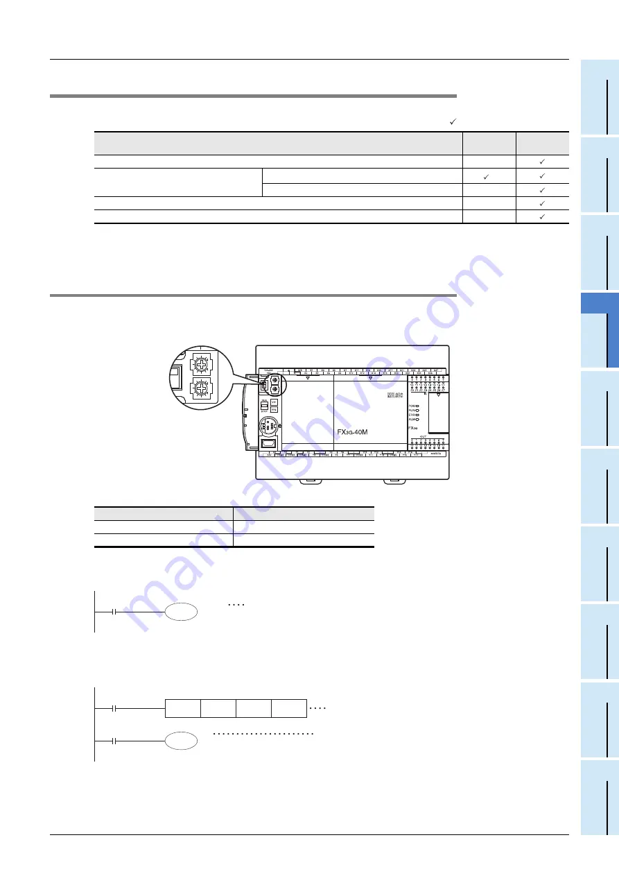
14.3.4 Built-in variable analog potentiometer function
The main unit has two built-in variable analog potentiometers (shown in the figure below).
The current value increases from 0 to 255 when a variable analog potentiometer is turned clockwise.
The current value of each variable analog potentiometer is stored in special data registers shown below.
1. Use example 1 of variable analog potentiometer
The current value of VR1 is used as the set value of a timer.
2. Use example 2 of variable analog potentiometer
The current value of VR2 multiplied by "10" is used as the set value of a timer.
Item
In running
status
In stopped
status
Batch writing of file registers (D) and extension file registers (ER)
-
Writing of program to PLC
Partial modification of program
*1
Modification of whole program (batch writing)
-
Writing of parameters to PLC
-
Writing of comments to PLC
-
Volume
Data register to store current value
VR1 : variable analog potentiometer1
D8030 (Integer from 0 to 255)
VR2 : variable analog potentiometer2
D8031 (Integer from 0 to 255)
Enlarged view
D8030
T0
The current value of VR1 is used as the set value of the timer T0.
The setting range in this example using T0 (100ms timer) is from 0 to
25.5 sec.
D0
The current value of VR2 multiplied by "10" is used as the
set value of the timer T1.
The setting range in this example using T1 (100ms timer)
is from 0 to 255 sec.
MUL
M8000
T1
D8031
K10
D0(D1)
The value of D8031 is multiplied by "10", and stored in
D0(D1).


