background image

GOT-F900 SERIES (CONNECTION)

Installation and Wiring of Handy GOT 5

5-2

Note

Even if momentary power failure of less than 5 ms occurs in the power supply, the Handy GOT
continues the operation.
If long-time power failure or voltage drop occurs, the Handy GOT stops the operation. When the
power supply is recovered, the Handy GOT restarts the operation. 

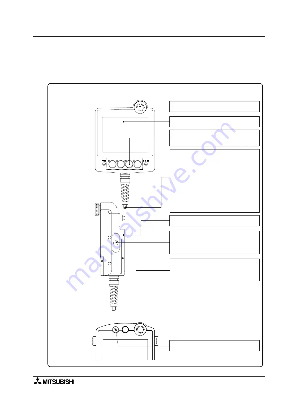
Index of each part

F940 Handy GOT

F940 Handy GOT RH model

Detecting voltage drop of the battery

 23.4

Controlling the grip switch

⇒ 

5.11

Controlling the grip switch (F940 Handy GOT RH
model)

 5.12

Wiring the emergency stop switch

 5.10

Wiring the selector switch with key

 5.13

Controlling the ON/OFF status of the backlight

 23.3

Wiring the operation switches, and assigning
functions to them
Preparing the switch name sheet

 5.9

Selecting and connecting the external cable

 5.4

Wiring the power supply

 5.8

Connecting the PLC

 Section 8 and later

   (described for each connected PLC)
 - When connecting the FX Series PLC...Section 8
 - When connecting the A Series PLC...Section 9
Connecting the PC (for screen data transfer)

 6.3 (only in the case of F943 Handy GOT)

Function to connect two or more GOT units

 Section 7

Connector conversion box F9GT-HCNB

 5.16

Connecting the PC (for screen data transfer)

⇒ 

6.2.1

Connecting the PC (for sequence program transfer
and monitoring)

 6.2.2

Содержание F920GOT-BBD-K-E

Страница 1: ... E F920GOT BBD5 K E F930GOT K F930GOT BWD E F930GOT BBD K E F940GOT F940WGOT TWD E F940GOT SWD E LWD E Handy GOT F940GOT SBD H E LBD H E F943GOT SBD H E LBD H E F940GOT SBD RH E LBD RH E F943GOT SBD RH E LBD RH E Screen creation software GT Designer2 SW D5C GTD2 E GT Designer SW D5C GOTR PACKE FX PCS DU WIN E ...

Страница 2: ...nstallation Manual F930GOT K Installation Manual F940GOT Installation Manual F940WGOT Installation Manual If in doubt at any stage of the installation of GOT F900 SERIES GRAPHIC OPERATION TERMINAL always consult a professional electrical engineer who is qualified and trained to the local and national standards which apply to the installation site If in doubt about the operation or use of GOT F900 ...

Страница 3: ...i GOT F900 SERIES GRAPHIC OPERATION TERMINAL HARDWARE MANUAL CONNECTION Manual number JY992D94801 Manual revision C Date MARCH 2003 GOT F900 SERIES CONNECTION ...

Страница 4: ...GOT F900 SERIES CONNECTION ii ...

Страница 5: ...07 278 695 Please tick the box of your choice What condition did the manual arrive in Good Minor damage Unusable Will you be using a folder to store the manual Yes No What do you think to the manual presentation Tidy Unfriendly Are the explanations understandable Yes Not too bad Unusable Which explanation was most difficult to understand Are there any diagrams which are not clear Yes No If so whic...

Страница 6: ...GOT F900 SERIES CONNECTION iv ...

Страница 7: ...perators of the completed equipment should be trained to use that product in a safe and coordinated manner in compliance to established safety practices The operators should also be familiar with documentation which is connected with the actual operation of the completed equipment Note Note the term completed equipment refers to a third party constructed device which contains or uses the product a...

Страница 8: ...out screen creation for GOT F900 refer to the OPERATION MANUAL attached to the screen creation software Make sure that this manual is delivered to the end user Trademarks and registered trademarks Microsoft Windows Windows 98 Windows NT Windows 2000 Windows XP Windows Millennium Edition MS DOS MS and Windows logos are registered trademarks of Microsoft Corporation USA in the USA and other countrie...

Страница 9: ...Software 3 8 3 2 2 Screen Creation Software Version Corresponding to GOT F900 Series 3 10 3 2 3 Screen Creation Software Corresponding to Each Connected Equipment 3 11 3 3 Device Names Which can be Monitored 3 13 3 3 1 Devices in GOT F900 3 13 3 3 2 PLC by Mitsubishi 3 14 3 3 3 PLC Units Manufactured by Other Companies 3 20 3 4 Hardware Specifications 3 28 4 Installation and Wiring of F920GOT K F9...

Страница 10: ... Wiring 5 31 5 8 Wiring for 24V DC Power Supply and Class D Grounding 5 33 5 9 Wiring and Handling of Operation Switches SW1 to SW4 5 34 5 9 1 Handling of operation switches 5 34 5 9 2 Preparation of Operation Switch Name Sheet 5 36 5 10 Wiring and Handling of Emergency Stop Switch ES1 5 38 5 11 Handling of grip switch excluding RH model 5 40 5 11 1 Function of Grip Switch 5 40 5 11 2 Setting in m...

Страница 11: ... is Connected through RS 422 7 2 7 2 2 When First GOT Unit is Connected through RS 232C 7 4 7 2 3 When Connection is Changed from RS 422 to RS 232C 7 5 7 3 Rules in Configuration 7 6 7 3 1 Connection Method 7 6 7 3 2 Communication Port Number Table 7 7 7 3 3 Connection Concept in Each Model Name 7 7 7 4 Connection of Four or More Display Units 7 8 7 5 Cautions on Connecting Two or More GOT Units 7...

Страница 12: ...er Link Connection 10 9 10 3 1 Communication Setting Specifications 10 9 10 3 2 Setting Examples 10 10 10 4 Caution on Use of MELSEC QnA Series PLC 10 12 10 4 1 Caution when the GOT is connected to the serial communication unit 10 12 10 4 2 Caution when the GOT is connected to the computer link for the A Series PLC 10 12 10 5 Setting of Connected Equipment for GOT 10 13 10 6 Cable Diagram 10 22 10...

Страница 13: ...ter 13 11 13 4 4 Specification of the program operation PG devices 13 12 13 4 5 Caution on setting of the calibration parameters Pr900 to Pr905 13 12 13 4 6 Restriction in simultaneous specification of PG and Pr devices on one screen 13 12 13 4 7 Caution on connecting to the PU port only in the E500 and the A500 13 12 13 5 Correspondence Between Devices of GOT and Parameters 13 13 13 6 FREQROL Inv...

Страница 14: ... Modes in the SYSMAC C Series PLC 15 17 15 7 2 Forced ON OFF on the device monitor screen of the GOT F900 15 17 15 7 3 Restriction in functions 15 17 15 8 Setting of Connected Equipment for GOT 15 18 15 9 Cable Diagram 15 24 15 10Troubleshooting 15 28 16 Connection of FLEX PC N Series PLC Manufactured by Fuji Electric 16 1 16 1 System Condition 16 1 16 2 System Configuration 16 2 16 2 1 Configurat...

Страница 15: ...fications 19 5 19 4 Setting in MicroLogix 19 6 19 4 1 Communication Setting Specifications 19 6 19 4 2 GOT F900 Transmission Specifications 19 6 19 5 Device Specification Method 19 7 19 5 1 Device Format 19 7 19 5 2 File Number and Element Range 19 9 19 5 3 Restriction in Device Specification 19 9 19 6 Caution on Use of SLC500 MicroLogix Series PLC 19 10 19 6 1 Device setting in advance 19 10 19 6...

Страница 16: ...ar Code Data Setting 22 6 22 3 4 Sequence Program Example 22 7 22 4 Caution on Use of Bar Code Reader 22 8 22 4 1 Caution on bar code reader setting 22 8 22 5 Setting of Connected Equipment for GOT 22 9 22 6 Cable Diagram 22 12 22 7 Troubleshooting 22 12 23 Appendix 23 1 23 1 Backlight ON OFF Status Control Method and Replacement Procedure 23 2 23 1 1 Backlight Control Operation 23 2 23 1 2 Assign...

Страница 17: ...tions and function of the GOT and the screen creation software GT Designer2 GT Designer and DU WIN GOT F900 PLC Personal computer GOT F900 OPERATION MANUAL GT Designer2 version No JY997D09101 GOT operation manual for GT Designer2 separate manual Screen creation software manual GT Designer2 OPERATING MANUAL GOT F900 OPERATION MANUAL No JY992D94701 Screen creation software manual GT Designer OPERATI...

Страница 18: ...rmation Offered by Model name and In built Fonts Introduction Outline of Connection Types Section 1 Applicable PLC and connection type Section 2 Screen Creation Software Version Device Names Which can be Monitored This manual can be classified as follows in accordance with the type of GOT F900 Series F920GOT K F930GOT K F940GOT or F940WGOT Series Read from Section 3 Handy GOT Series Read from Sect...

Страница 19: ... F920GOT BBD5 K E F920GOT BBD K E INSTALLATION MANUAL No JY997D02201 To learn the features of the main unit To confirm the specifications of the main unit To learn the name of each part of the main unit To learn how to install the main unit and wire the power supply To look at the external dimensions diagram of the main unit F930GOT INSTALLATION MANUAL No JY992D95701 To learn the features of the m...

Страница 20: ...eatures of the main unit To confirm the specifications of the main unit To learn the name of each part of the main unit To learn how to install the main unit To look at the external dimensions diagram of the main unit OPERATION MANUAL of GOT sent separately Describes how to operate system screens and how to create and operate user screens and covers all of the F920GOT K F930GOT K F940GOT and Handy...

Страница 21: ... the monitor screen To learn how to use the library function To learn how to draw graphics GT Designer2 SW D5C GTD2 E REFERENCE MANUAL separate manual Consult with the distributor from which you have purchased GT Designer2 To learn the types and specifications of GOT screens To learn the device range which can be monitored To learn common items to be set at the beginning To learn how to set and di...

Страница 22: ... To install the software to the personal computer To start up the software To learn how to connect the personal computer to the GOT To learn the screen configuration of the software To learn how to use the help function MODEL CODE 09R910 OPERATION MANUAL It is included with the FX PCS DU WIN E ...

Страница 23: ... F940GOT F940GOT SWD F940GOT LWD RS 422 1 RS 232C 1 Japanese models F940GOT SWD E F940GOT LWD E F940GOT SWD C F940GOT LWD C RS 422 1 RS 232C 1 World spec models F943GOT F943GOT SWD F943GOT LWD RS 232C 2 Japanese models F930GOT K F930GOT BBD K RS 422 1 RS 232C 1 Japanese models F930GOT BBD K E F930GOT BBD K C World spec models F930GOT F930GOT BWD RS 422 1 RS 232C 1 Japanese models F930GOT BWD E F93...

Страница 24: ...nterface 3 Screen shape None Standard W Wide screen 4 Screen color T TFT type 256 color LCD S STN type 8 color LCD L STN type black and white LCD B STN type blue LCD 5 Panel color W White B Black 6 Input power supply specifications D 24V DC D5 5V DC 7 Various keys None Not with a key K With a key 8 Type None Panel face installation type H Handy GOT RH Handy GOT 9 Overseas models E C T F9 GOT 1 2 4...

Страница 25: ...s user screen 3 Japanese English Korean Chinese Western Europe At factory Can be switched to Shift JIS level 1 kanji set Shift JIS level 2 kanji set English Korean Simplified Traditional Italian Dutch Swedish Spanish German Portuguese French F940WGOT F940WGOT TWD Japanese English F940WGOT TWD E English Japanese F940WGOT TWD C Chinese Simplified English F940GOT F94 GOT SWD Japanese English F94 GOT ...

Страница 26: ... Series Generic name of FX0 Series main units FX0S Series Generic name of FX0S Series main units FX1S Series Generic name of FX1S Series main units FX0N Series Generic name of FX0N Series main units FX1N Series Generic name of FX1N Series main units FX1 Series Generic name of FX1 Series main units FX Series Generic name of FX Series main units FX2 Series Generic name of FX2 Series main units FX2N ...

Страница 27: ...Parts and setting data on the screen Windows95 Abbreviation of Microsoft Windows95 Windows98 Abbreviation of Microsoft Windows98 Windows NT4 0 Abbreviation of Microsoft Windows NT Workstation 4 0 Windows 2000 Abbreviation of Microsoft Windows 2000 Professional Windows Generic name of Windows95 Windows98 Windows NT4 0 and Windows2000 Personal computer PC Personal computer compatible with Windows to...

Страница 28: ...S CONNECTION Introduction 1 1 12 Abbreviation generic name term Description Connection diagram BK Black W White Y Yellow BR Brown BL Blue GY Gray O Orange PL Purple PK Pink FGR Fresh green SB Sky blue R Red GR Green ...

Страница 29: ...tion types supported by the GOT F900 having the lastest OS version 2 1 1 GOT type list and index Connected equipment Connection destination Description Reference F920GOT K F930GOT F930GOT K F940GOT F940WGOT Name of each part installation and power supply wiring Chapter 4 Handy GOT Dedicated wiring and functions of Handy GOT such as name of each part installation cables dedicated to Handy GOT and s...

Страница 30: ...mode CPU direct connection Chapter 11 Serial communication unit CPU direct connection Q Series multi CPU CPU direct connection Chapter 11 Serial communication unit CPU direct connection FX positioning unit 10GM 20GM CPU direct connection Chapter 12 FREQROL Series inverter CPU direct connection Chapter 13 PLC by other companies General purpose equipment such as microcomputer board CPU direct connec...

Страница 31: ... the FX A QnA Q Series FX Series PLC 1 CPU direct connection RS 422 GOT F900 is connected to the programming port of the FX Series PLC When a personal computer is connected to the GOT F900 sequence programs can be created By attaching the optional RS 422 communication board a programming port can be added As a result a GOT F900 or personal computer for sequence programs can be connected to each po...

Страница 32: ... S F X 1 N F X 2 N F X 2 N C P e r s o n a l c o m p u t e r P r i n t e r B a r c o d e r e a d e r P e r s o n a l c o m p u t e r P r i n t e r B a r c o d e r e a d e r E i t h e r o n e u n i t 2 a p e r s o n a l c o m p u t e r a n d o n e u n i t i n F 9 4 0 W G O T E i t h e r o n e u n i t 2 a p e r s o n a l c o m p u t e r a n d o n e u n i t i n F 9 4 0 W G O T M E L S E C F X S e r i...

Страница 33: ...e between two ports Connecting two GOT F900 units to one serial communication unit is not allowed A personal computer printer or bar code reader can be connected only when the GOT is equipped with two RS 232C channels 1 GOT F900 can be connected to the multi CPU system only when the connection consists of QCPU A motion controller or CPU of a personal computer cannot be used concurrently 2 Excludin...

Страница 34: ...personal computer printer or bar code reader can be connected only when the GOT is equipped with RS 422 and RS 232C 1 Excluding the F920GOT K G O T F 9 0 0 1 C o m p u t e r l i n k u n i t f o r M E L S E C A S e r i e s P O W E R R S 4 2 2 o r R S 2 3 2 C R S 2 3 2 C A c o m p u t e r l i n k u n i t E i t h e r o n e u n i t 2 P r i n t e r B a r c o d e r e a d e r M E L S E C A S e r i e s M ...

Страница 35: ... GOT F900 units can be connected to the serial communication connector of a personal computer or microcomputer board 1 Excluding the F920GOT K 2 Excluding the F920GOT K PLC by Omron Upper link connection One GOT F900 unit can be connected to a port having the upper link communication function of the SYSMAC C Series C200H C200HE C200HG C200HX CQM1 CS1 CPM1A CPM2A CPM2C CJ1 1 Excluding the 5V type F...

Страница 36: ...r or bar code reader can be connected only when the GOT is equipped with two RS 232C channels 1 Excluding the 5V type F920GOT K 2 Excluding the F920GOT K F L E X P C N G O T F 9 0 0 1 P O W E R R S 2 3 2 C R S 4 2 2 o r R S 2 3 2 C L i n k u n i t E i t h e r o n e u n i t P r i n t e r B a r c o d e r e a d e r C P 9 2 0 0 S H M P 9 2 0 M P 9 3 0 G O T F 9 0 0 1 P O W E R R S 2 3 2 C R S 4 2 2 o ...

Страница 37: ...ader can be connected to the GOT F900 The connection shown below is available also in the Handy GOT However because the rear panel of the Handy GOT must be removed when a cable is connected to the RS 232C connector the waterproof ability and the operability operation of the Handy GOT while it is held by hand are lost Accordingly the connection shown below is not practical for the Handy GOT Printer...

Страница 38: ...GOT F900 SERIES CONNECTION Outline 2 2 10 MEMO ...

Страница 39: ...OS version and check whether it corresponds to the equipment to be connected OS type There are following five types of OS 3 1 1 How to Confirm OS Version of GOT F900 When the power of the GOT F900 is turned on the screen shown below is displayed for several seconds to indicate the series name and the version number version 2 10 in the lower right position The period of time to be displayed can be ...

Страница 40: ... 1 00 or later 1 00 or later 1 9 2 1 MELSEC A Series computer link connection Connection type name A computer link connection Connection to computer link unit AJ71UC24 A1SJ71C24 R4 A1SJ71UC24 R4 RS 422 1 00 or later 1 00 or later 1 00 or later 1 20 2 or later 9 2 2 AJ71UC24 A1SJ71C24 R2 A1SJ71UC24 R2 A1CPUC24 R2 A2CCPU24 RS 232C 9 2 3 Motion controller CPU direct connection Connection type name AC...

Страница 41: ...ter 1 20 2 or later 11 2 2 QJ71C24 QJ71C24 R2 RS 232C 11 2 3 MELSEC Q Series CPU direct connection Connection type name QCPU direct connection Q multiple PLC system Ver B or later Connection to programming port in Q CPU Q02CPU Q02HCPU Q06HCPU Q12HCPU Q25HCPU RS 232C 1 30 or later 6 30 or later 4 30 or later 1 00 or later 1 11 2 1 Connection to serial communication unit QJ71C24 RS 422 1 30 or later...

Страница 42: ...2 SYSMAC CS1 Series upper link Connection type name SYSMAC C Connection to RS 232C port built in CPU CS1G CPU45 V1 RS 232C 1 00 or later 6 00 or later 4 00 or later 1 20 2 or later 15 2 2 Connection to serial communication board unit CS1W SCB41 port 1 port 2 RS 422 1 00 or later 6 00 or later 4 00 or later 1 20 2 or later 15 2 1 RS 232C 15 2 2 CS1W SCU21 port 1 port 2 RS 232C 15 2 2 SYSMAC α α α α...

Страница 43: ...P 217IF RS 422 1 00 or later 5 00 or later 3 00 or later 17 2 1 RS 232C 17 2 2 Matsushita Electric Works FP Series CPU direct connection Connection type name FP Connection to COM port built in CPU FP0 Series FP0 T32CT FP2SH Series FP2 C2 RS 232C 1 10 or later 6 10 or later 4 10 or later 1 20 2 or later 18 2 1 Connection to tool port built in CPU FP0 Series FP0 T32CT FP2SH Series FP2 C2 RS 232C 1 1...

Страница 44: ...S7 972 0CA11 0XA0 RS 232C 1 00 or later 5 00 or later 3 00 or later 1 20 2 or later 20 2 1 SIMATIC S7 200 Series CPU direct connection SIMATIC S7 Series SIMATIC S7 Connection to port built in CPU S7 216 2 6ES7 216 2BD00 0XB0 PC PPI cable 6ES7 901 3BF20 0ZA0 RS 232C 1 20 or later 6 20 or later 4 20 or later 20 2 1 Connected equipment name and series name RS 232C RS 422 OS version Connection of two ...

Страница 45: ...are Applicable GOT F900 Series models and the correspondence to the connected equipment related to the OS version also vary depending on the version of the screen creation software In this section you can check the version of your screen creation software and confirm applicable GOT models and connectable equipment The table in Section 3 2 2 shows the screen creation software version corresponding ...

Страница 46: ...software For the GT Designer2 GT Designer and DU WIN you can confirm the version by selecting Help H About A from the menu bar a GT Designer2 b GT Designer c DU WIN Version 1 00A in this case SW1 indicates the major version SW D5C GTD2 J Japanese SW D5C GTD2 E English In the case of Version SW5 or later Version 5 09K Small version SW5 SW D5C GOTR PACKE SW5 indicates the large version An alphabet a...

Страница 47: ...ersion by checking the contents indicated on the media of the product a GT Designer2 CD ROM b GT Designer CD ROM c DU WIN FD MELSEC MITSUBISHI DATE 9812AA disc MODEL SW1D5C GTD2 E A version An alphabet at the end indicates the small version SW1D5C GTD2 E SW1 indicates the large version MELSEC MITSUBISHI DATE 9812AA disc MODEL SW2D5C GOTR PACKE In the case of Version SW4 or former A version An alph...

Страница 48: ... 20 F920GOT K 5V SW1 A 1 00A SW5 26C 5 26C 2 70 F920GOT K 24V SW1 C 1 02C F940 Handy GOT SW1 A 1 00A SW1 D 2 10 F940 Handy GOT RH model SW1 A 1 00A SW5 F 5 05F 2 50 F943 Handy GOT SW1 A 1 00A SW1 D 2 10 F943 Handy GOT RH model SW1 A 1 00A SW5 F 5 05F 2 50 ET 900 SW1 A 1 00A SW1 D 2 00 GOT F900 Series SW D5C GTD2 E SW D5C GOTRE PACK Version FX PCS DU WIN E Version F940WGOT SW1 C 1 02C SW5 F 5 05F 2...

Страница 49: ...t connection SW1 A 1 00A SW2 A 2 30 QnA computer link QCPU direct connection SW1 A 1 00A SW4 F 2 40 Q computer link QCPU direct connection multi CPU system SW1 A 1 00A SW5 P 5 13P Q computer link multi CPU system GM direct connection FX positioning unit SW1 A 1 00A SW5 K 5 09K 2 50 INV direct connection inverter Other companies Microcomputer connection general purpose communication SW1 A 1 00A SW1...

Страница 50: ...P Q computer link multi CPU system SW1 C 1 02C GM direct connection FX positioning unit SW1 C 1 02C SW5 K 5 09K 2 50 INV direct connection inverter SW1 C 1 02C Other companies Microcomputer connection general purpose communication SW1 C 1 02C SW1 E 2 00 SYSMAC C by Omron SW1 C 1 02C FLEX PC N by Fuji Electric SW1 C 1 02C Not applicable CP9200SH by Yasukawa Electric SW1 C 1 02C SW4 F FP by Matsushi...

Страница 51: ...N from Version 2 50 and later Allocation of devices for internal processing GB 0 to GB 131 and GD 0 to GD 99 are used for the processing inside the GOT F900 Note however that the devices with functions shown below are available for user use Device name Available range Device number representation Bit device GB GOT internal device GB0 to GB131 Not available except devices in table below Decimal GB1...

Страница 52: ...e register D D1000 D7999 D1000 D7999 Special data register D D8000 D8255 D8000 D8255 Index register Z 3 Z V 3 V GOT internal data register GD 1 GD100 GD1023 GD100 GD1023 Condition enabling data changes While the GOT is connected to the FX Series PLC data cannot be changed in set values specified directly of timers and counters and file registers in the following condition The following error messa...

Страница 53: ...ord device Data register D D0 D8191 D0 D8191 Special data register D D9000 D9255 D9000 D9255 Link register W W0 W1FFF W0 W1FFF Hexadecimal Timer T Present value TN0 TN2047 T0 T2047 Decimal Set value 3 TS0 TS2047 T0 T2047 Counter C Present value CN0 CN1023 C0 C1023 Set value 3 CS0 CS1023 C0 C1023 File register R 3 R0 R8191 R0 R8191 Accumulator A A0 A1 Index register Z V 4 Z0 Z6 Z0 Z Z V0 V6 V0 V V ...

Страница 54: ...ial link relay SB SB0 SB7FF SB0 SB7FF Timer T Contact TT0 TT32767 T0 T32767 Decimal Coil TC0 TC32767 Counter C Contact CT0 CT32767 C0 C32767 Coil CC0 CC32767 Special relay SM SM0 SM2047 SM0 SM2047 Retentive timer ST Contact SS0 SS32767 SS0 SS32767 Coil SC0 SC32767 SC0 SC32767 Step relay S S0 S32767 S0 S32767 GOT internal bit register GB 1 GB132 GB1023 GB132 GB1023 Word device Data register D D0 D3...

Страница 55: ...on of Peripheral Equipment 7 Connection of Two or More GOT Units 8 Connection of MELSEC F FX Series PLC 9 Connection of MELSEC A Series PLC 10 Connection of MELSEC QnA Series PLC Specification of PLC number when using Q multiple PLC system Specify the PLC number when appointing the device 0 CPU connected Control PLC if connected to the link 1 to 4 CPU with the specified number ...

Страница 56: ...7 X0 X377 Octal Output Y Y0 Y67 Y0 Y67 Internal relay M M0 M511 M0 M511 Decimal Special auxiliary relay SM M9000 M9175 M9000 M9175 GOT internal bit register GB GB132 1023 GB132 1023 Word device Data register D D0 D3999 D0 D3999 Special data register SD D9000 D9313 D9000 D9313 File register R D4000 D6999 D4000 D6999 Index register Z V Z0 Z6 32 bits Z 32 bits V0 V6 16 bits V 16 bits GOT internal dat...

Страница 57: ...setting the device Available setting range 0 to 31 b Station No specification indirect Specify the station number of the inverter indirectly using 16 bit GOT internal registers GD100 to GD115 when setting the device Multiple inverters can be changed on one screen Available setting range 100 to 115 The station No corresponds to each device of GD100 to GD115 Device name Setting range Device number r...

Страница 58: ...mal Special memory M 2 M8000 M8063 M8000 M8063 GOT internal bit register GB 4 GB132 GB1023 GB132 GB1023 Word device Word data D 3 D0 D4095 D0 D4095 Special memory M 2 D8000 D8015 D8000 D8015 GOT internal data register GD 4 GD100 GD1023 GD100 GD1023 Device name Setting range Device number representation GT Designer 2 DU WIN Bit device I O relay 000000 614315 00000 51115 Decimal Internal auxiliary r...

Страница 59: ...Hexadecimal Output Y Y0 Y7FF Y0 Y7FF Internal relay M M0 M1FFF M0 M1FFF Latch relay L L0 L1FFF L0 L1FFF State S S0 S7FF S0 S7FF Special internal relay M M800 M81FF M800 M81FF GOT internal bit register GB GB132 GB1023 GB132 GB1023 Word device Timer T T0 T3FF T0 T3FF Counter C C0 C1FF C0 C1FF Data register D D0 D2FFF D0 D2FFF Special data register D D8000 D81FF D8000 D81FF Link register W W0 W3FFF W...

Страница 60: ...0 to GD127 in the F920GOT K Device name Setting range Device number representation GT Designer 2 DU WIN Bit device Input relay X 3 X0000 X511F X0000 X511F Decimal 6 Output relay Y Y0000 Y511F Y0000 Y511F Internal relay R 4 R0000 R910F R0000 R910F Link relay L 1 L0000 L639F L0000 L639F Error alarm relay E 2 3 E0 E2047 E0 E2047 Decimal Timer contact T 3 T0 T3071 T0 T3071 Counter contact C 3 C0 C3071...

Страница 61: ...00 B255255F Hexadecimal Timer T timing bit TT0040000 TT0042550 TT0100000 TT2552550 Decimal Timer T completion bit TN0040000 TN0042550 TN0100000 TN2552550 T0040000 T0042550 T0100000 T2552550 Counter C up counter CU0050000 CU0052550 CU0100000 CU2552550 Counter C down counter CD0050000 CD0052550 CD0100000 CD2552550 Counter C completion bit CN0050000 CN0052550 CN0100000 CN2552550 C0050000 C0052550 C01...

Страница 62: ... CD C5 0 CD C5 255 CD C10 0 CD C255 255 CD Counter C completion bit C5 0 DN C5 255 DN C10 0 DN C255 255 DN C5 0 DN C5 255 DN C10 0 DN C255 255 DN GOT internal bit register GB 2 GB132 GB1023 GB132 GB1023 Word device Timer T 1 set value T4 0 PRE T4 255 PRE T10 0 PRE T255 255 PRE T4 0 PRE T4 255 PRE T10 0 PRE T255 255 PRE Decimal Timer T 1 current value T4 0 ACC T4 255 ACC T10 0 ACC T255 255 ACC T4 0...

Страница 63: ... 15 Hexadecimal Timer T timing bit T3 0 TT T255 255 TT T3 0 TT T255 255 TT Decimal Timer T completion bit T3 0 DN T255 255 DN T3 0 DN T255 255 DN Counter C up counter C3 0 CU C255 255 CU C3 0 CU C255 255 CU Counter C down counter C3 0 CD C255 255 CD C3 0 CD C255 255 CD Counter C completion bit C3 0 DN C255 255 DN C3 0 DN C255 255 DN GOT internal bit register GB 2 GB132 GB1023 GB132 GB1023 Word dev...

Страница 64: ...7 7 Bit memory M M00 M317 M0 0 M31 7 Special Memory SM SM00 SM1947 SM0 0 SM194 7 Timer T 1 T0 T255 T0 T255 Counter C 1 C0 C255 C0 C255 Sequence Control Relay S S00 S317 S0 0 S31 7 GOT internal bit register GB GB132 GB1023 GB132 GB1023 Word device Variable Memory V 6 VW0 VW5118 VW0 VW5118 Input I 6 IW0 IW6 IW0 IW6 Output Q 6 QW0 QW6 QW0 QW6 Analog Input AI 2 6 AIW0 AIW30 AIW0 AIW30 Analog Output AQ...

Страница 65: ... representation A decimal point exists when using the GT Designer 2 but not when using the DU WIN Device name Setting range Device number representation GT Designer 2 DU WIN Bit device Input relay I I0 I5117 I0 0 I511 7 Decimal Output relay Q Q0 Q5117 Q0 0 Q511 7 Bit memory M M0 M20477 M0 0 M2047 7 GOT internal bit register GB 1 GB132 GB1023 GB132 GB1023 Word device Present value of timer T T0 T51...

Страница 66: ...as and much dusts Vibration resistance Impact resistance In conformance to JIS B3502 and IEC 61131 2 147 m s2 3 times in each of X Y and Z directions Noise resistance By noise simulator of 1 000 Vp p in noise voltage 1 µs in noise width and 30 to 100 Hz in frequency Withstand voltage 500V AC for 1 min between all power terminals and ground terminal Insulation resistance 5 MΩ or more by 500V DC meg...

Страница 67: ...DC 70mA 24V DC 220mA 5V DC 180mA 5V DC 300mA 24V DC 200mA 24V DC Built in irreplaceable Built in irreplaceable Operation continues against power failure of 5ms or less Operation continues against power failure of 5ms or less FX2NC 32BL life Approx 3 years FX2NC 32BL life Approx 3 years 0 50 C 0 50 C 0 40 C 35 to 85 RH no condensation Free from corrosive gas and much dusts In conformance to JIS B35...

Страница 68: ...mergency stop switch Keylock switch Ten key keypad 0 9 Cursor key ENT ESC SET DEV Lamp Power indicator LED 1 LED green Operation indicator LED Function key LED 8 switches green Grip switch indicator LED Buzzer 1 Buzzer Built in buzzer Provided Provided Provided Item F940WGOT F940GOT F930GOT K Product model name F940WGOT SWD E F940GOT SWD E F940GOT LWD E F930GOT BWD E F930GOT BBD K E Serial interfa...

Страница 69: ...fe 100 000 times or more 1 switch AH165 VR02 manufactured by Fuji Electric individual wiring 2b contact 1A 24V DC resistance load Life 100 000 times or more 1 switch with 2 keys AS6M 2KT1PB manufactured by IDEC Corporation individual wiring c contact 1A 24V DC resistance load Life 100 000 times or more 0 9 ENT ESC SET DEV 1 LED green 1 LED green 4 LED green 4 LED green 1 LED green 1 LED green Prov...

Страница 70: ...GOT F900 SERIES CONNECTION Specifications 3 3 32 MEMO ...

Страница 71: ...930GOT K F940 W GOT has the DC power specifications Connect the DC power cable to dedicated terminals as described in this manual If the AC power supply is connected to power terminals the F930GOT F940 W GOT may be burnt Mount and connect a fuse of 2 A to the 24V DC power supply Connect the and sides of the DC power supply correctly as described in this manual If the power supply is connected reve...

Страница 72: ...ning torque of 0 5 to 0 8 N m so that troubles are not caused Index of each part examples F940GOT and F930GOT K Detecting voltage drop of the battery 23 4 R S 2 3 2 C R S 4 2 2 24VDC Controlling the ON OFF status of the backlight 23 3 Wiring the power supply 4 7 F940GOT F930GOT K Assigning functions to the function keys Preparing the key name sheet 4 8 Connecting the PLC Section 8 and later descri...

Страница 73: ...ch Part You can learn the name of each part of the F930GOT F940 W GOT 4 2 Processing of Panel Face You can learn the dimension of the processing on the panel face 4 3 Installation You can learn the method to install the F920GOT K F930GOT F930GOT K F940 W GOT 4 4 Connector Pin Layout and Signal Name You can check the connector signal names 4 5 Item name Description Reference Outline of Internal Wir...

Страница 74: ...pply of the PLC Prepare an external power supply 2 The cable to connect the 5V type F920GOT K to the FX FX2C A QnA and Q Series PLC needs to be prepared by the user The 5V DC power is supplied from the PLC Prepared by user FX 50DU CAB0 M PLC Connection cable Wiring inside panel GOT F900 F940GOT F940WGOT FX 40DU CAB M QC30R2 Power supplied from external power supply 1 or service power supply of PLC...

Страница 75: ...d in the size of 1 2 to 4 in height and 1 to 4 in width 4 2 2 Rear Panel 1 Power terminals Supply the power to the GOT F900 and perform the grounding Excluding the 5 V type F920GOT K 2 Battery Stores the sampling data the alarm history and the current time The screen data is stored in the built in flash memory and kept stored even if the life of the battery is expired 3 Extension interface Connect...

Страница 76: ...ation software Use this port also to connect a PLC or microcomputer board through RS 232C In the F920GOT K only Q Series PLC can be connected Use this port also to connect two or more GOT units through RS 232C a bar code reader or a printer excluding the F920GOT K The two port interface function is available A personal computer which has started up the PLC software can be connected here 3 PLC port...

Страница 77: ... connect a printer or bar code reader Another GOT can be connected here only when the PLC is connected to 3 RS 232C port The two port interface function is available A personal computer which has started up the PLC software can be connected here When connecting a PLC through a computer link unit use the port 1 2 or 3 In the F940WGOT when connecting a personal computer and transferring the screen d...

Страница 78: ...tion space below 1 Panel cut dimension Unit mm inches Make sure that the processing accuracy is 0 to 1 mm Make sure that the thickness of the installation panel is 5 mm or less 2 Installation space Reference For the details refer to the next page Unit mm inches The dimension above is offered for reference F920GOT K F930GOT F930GOT K F940GOT F940WGOT W 92 3 63 137 5 39 155 6 10 153 6 02 206 8 11 H ...

Страница 79: ...ed earlier 1 F920GOT K F930GOT F930GOT K and F940GOT When installing the GOT inside the panel while placing the screen laterally set the installation angle to 0 to 90 while the temperature inside the panel during operation is 0 to 50 C 2 F940WGOT When installing the GOT on the panel surface while placing the screen laterally set the installation angle to 90 while the temperature inside the panel d...

Страница 80: ...metal fixture external shape 168 6 61 94 5 3 72 20 0 79 67 2 64 20 0 79 104 5 4 11 20 0 79 20 0 79 108 5 4 27 30 1 18 cable 20 0 79 20 0 79 14 5 0 57 37 5 1 48 5 0 20 or less 6 4 0 25 COM1 RS232C COM0 RS422 169 6 65 14 5 0 57 154 6 06 7 0 28 7 0 28 b a 134 5 28 70 2 76 cable 10 0 39 5 0 20 86 3 39 7 0 28 10 0 39 10 0 39 86 3 39 99 3 90 screw center 168 6 61 109 4 29 metal fixture external shape 35...

Страница 81: ...MELSEC A Series PLC 10 Connection of MELSEC QnA Series PLC a b 2 4 V D C 5 7 2 2 4 1 5 2 5 9 8 1 2 0 4 7 2 1 6 2 6 3 8 s c r e w c e n t e r 1 7 2 6 7 7 m e t a l f i x t u r e e x t e r n a l s h a p e 1 3 0 5 1 2 s c r e w c e n t e r 1 4 0 5 5 1 m e t a l f i x t u r e e x t e r n a l s h a p e 5 0 2 0 o r l e s s L a t e r a l i n s t a l l a t i o n Longitudinal installation a 152 5 98 162 6 ...

Страница 82: ... e r 2 2 5 8 8 6 m e t a l f i x t u r e e x t e r n a l s h a p e a 1 2 3 7 0 6 2 7 8 b 5 0 2 0 o r l e s s L a t e r a l i n s t a l l a t i o n 1 3 3 5 2 4 s c r e w c e n t e r 1 4 3 5 6 3 m e t a l f i x t u r e e x t e r n a l s h a p e 2 2 5 8 8 6 m e t a l f i x t u r e e x t e r n a l s h a p e 2 1 5 8 4 6 s c r e w c e n t e r 2 0 5 8 0 7 a L o n g i t u d i n a l i n s t a l l a t i o n...

Страница 83: ...nel cut dimension refer to the previous page 1 Inserting the GOT into the panel face Attach a packing to the GOT Insert the GOT from the front of the panel face a GOT b Packing c Installation hole 2 Fixing the GOT Hang the hook of the metal fixture offered as accessory to installation hook holes in the GOT Tighten a tightening bolt offered as accessory securely in each position The GOT can be fixe...

Страница 84: ...4 V type F930GOT F930GOT K F940GOT F940WGOT D sub pin number RS 422 RS 232C Application 1 TXD SDA NC Signal wire for communication with PLC For the wiring refer to the section corresponding to the connected PLC 2 RXD RDA RD RXD 3 RTS RSA SD TXD 4 CTS CSA ER DTR 5 SG GND SG GND 6 TXD SDB DR DSR 7 RXD RDB RS RTS 8 RTS RSB CS CTS 9 CTS CSB User cannot use 5 1 9 6 RS 422 9 pin D Sub female 1 5 6 9 RS ...

Страница 85: ...l computer The 24V type F920GOT K and F930GOT K CPU memory LCD panel Touch switch circuit F930GOT K only ƒL ƒpƒbƒg Display circuit Serial communication unit CPU communication circuit I O interface 1 F930GOT K only Power supply circuit 5V DC power is supplied from PLC via RS 422 RS 232C port Ten key pad Cursor key Function keys with indicator LEDs 1 The 5V type F920GOT K only POWER LED F940GOT only...

Страница 86: ...1S FX0N Series PLC an external power supply is required c In the case of F940WGOT The current consumption is as shown in the table above Supply the power from the external power supply 2 Momentary power failure excluding only the 5 V type F920GOT K Even if momentary power failure of less than 5ms occurs in the power supply the GOT F900 continues the operation If long time power failure or voltage ...

Страница 87: ...ired because power is supplied to the F920GOT K via a communication cable 6 2mm 0 24 or less 6 2mm 0 24 or less φ3 2 0 13 φ3 2 0 13 Terminal Terminal screw Pressure terminal When wiring one cable to a terminal 6 2mm 0 24 or less 6 2mm 0 24 or less φ3 2 0 13 φ3 2 0 13 Terminal Terminal screw Pressure terminal When wiring two cables to a terminal 6 3mm 0 25 or more 6 3mm 0 25 or more 6 2mm 0 24 or l...

Страница 88: ...ifferent perform dedicated ground ing to the PLC and to the F930GOT F930GOT K F940 W GOT separately F 9 4 0 G O T F 9 4 3 G O T G r o u n d i n g r e s i s t a n c e 1 0 0 W o r l e s s 2 4 V D C p o w e r s u p p l y F 9 4 0 W G O T G r o u n d i n g r e s i s t a n c e 1 0 0 W o r l e s s 2 4 V D C p o w e r s u p p l y P L C G r o u n d i n g r e s i s t a n c e 1 0 0 W o r l e s s 2 4 V X 4 X ...

Страница 89: ... in the screen creation software Select the followings on the menu in the screen creation software Function of function key LED indicator on function key Screen creation software GT Designer2 Unit of project Common Operation Panel Unit of screen Right click the screen No to be set among base screens displayed in the project workspace then select Screen Panel Objects Lamp External Lamp GT Designer ...

Страница 90: ...en LED is lit when the device allocated to the function key using the screen creation software is turned ON a Allocation of device to control LED b Setting in creation software The devices to display the indicator LEDs on function keys should be set in the screen creation software For details refer to Setting of connected equipment for GOT described later c Program example The indicator LEDs on th...

Страница 91: ...HP sheet transparent and colorless sheet b Write down the names of the switches used on the mount sheet Function key c When the work in b is completed copy the contents of the name sheet base on an OHP sheet in the actual dimensions 100 using a copy machine When using a different OHP sheet use the following type Make sure that the selected OHP sheet can be used in a copy specification Recommended ...

Страница 92: ...in the unit of screen is valid For the F2 key the setting Switches to the screen No 10 set on the base screen is valid For the F3 key only the setting Works as the M10 switch set on the overlap window 1 is valid High Low F1 F2 F3 F4 F5 F6 Works as the M0 switch Setting on the operation panel unit project Screen F1 F2 F3 F4 F5 F6 Screen F1 F2 F3 F4 F5 F6 Screen F1 F2 F3 F4 F5 F6 Overlap window 1 sc...

Страница 93: ... Wiring of Handy GOT 6 Connection of Peripheral Equipment 7 Connection of Two or More GOT Units 8 Connection of MELSEC F FX Series PLC 9 Connection of MELSEC A Series PLC 10 Connection of MELSEC QnA Series PLC 4 8 4 Label pattern F930GOT K Copy this pattern to the OHP sheet offered as an accessory Insertion direction With switch frames Without switch frames Actual size Insertion direction ...

Страница 94: ... read b Open a user screen to be set Any screen is available as far as it has been already created Select and display the base screen B 1 in this example LED setting Only in F930GOT K c Select Object Lamp External on the menu d Click the Dev button input a bit device to be assigned then click OK Refer to Caution on setting of Lamp External described later The Lamp dialog box appears Switch setting...

Страница 95: ...MELSEC F FX Series PLC 9 Connection of MELSEC A Series PLC 10 Connection of MELSEC QnA Series PLC Unit of screen individual Select Project Base Screen from the project work space left click the screen No to be set then select Operation Panel on the submenu In the case of F920GOT K In the case of F930GOT K f Click Available Operation Panel to display the check mark g Click a box indicating a functi...

Страница 96: ...heck box is valid only in the F920GOT K F930GOT K and Handy GOT Do not set it in any other series 2 Several boxes displayed on the Operation Panel dialog box shown in the table below correspond to the function keys Note that key codes cannot be set to the function keys though the contents of operation setting are equivalent to those for touch switches Setting up the function keys for the F920GOT K...

Страница 97: ... of Peripheral Equipment 7 Connection of Two or More GOT Units 8 Connection of MELSEC F FX Series PLC 9 Connection of MELSEC A Series PLC 10 Connection of MELSEC QnA Series PLC Screen display of GT Designer2 Operation Panel Available Operation Panel indicates that a switch operation is set Click a box indicating a function key then set its functions example F1 Switch functions Currently set switch...

Страница 98: ...arted up and the screen data to be set is read b Open a user screen to be set Any screen is available as far as it has been already created Select and display the base screen B 1 in this example LED setting c Select Draw Animation Display Lamp on the menu d On the Basic tab click Lamp External to display the check mark click the Device button input a bit device to be assigned then click OK Refer t...

Страница 99: ...devices 00 of X000 in Edit Operation Panel in the screen creation software Note that key codes cannot be set to the function keys though the contents of operation setting are equivalent to those for touch switches Note also that device names of X000 do not indicate device names of the connected equipment PLC Allocation table of function key Screen display of GT Designer 00 01 02 03 04 05 06 07 F92...

Страница 100: ... appears d Select Object Indicator Output Indicator on the menu Output Indicator is displayed in the New Object Type field on the Objects Scr Common window e Click the Insert button Input a bit device to be assigned and click OK Refer to Caution on setting of Output Indicator next page Close all windows except the Screen List window The Output Indicator dialog box appears Switch setting f Select C...

Страница 101: ...evice assigned on the Output Indicator dialog box is not included in the bit device range in set View Project System Settings Interface Devices Function key setting procedure and cautions The switch operations can be set to devices external keys 0 to 7 corresponding to F1 to F8 The setting method and operations are the same as function allocation for touch keys however note that no key code settin...

Страница 102: ...GOT F900 SERIES CONNECTION Installation and Wiring of F920GOT K F930GOT K F940 W GOT 4 4 32 MEMO ...

Страница 103: ...ide the Handy GOT before starting the installation or wiring work Otherwise electrical shock and damages of the Handy GOT may be caused Make sure to attach the rear cover to the Handy GOT before turning on the power and starting operation after the installation or wiring work Otherwise electrical shock may be caused Caution The Handy GOT has the DC power supply specifications Connect the DC power ...

Страница 104: ...he emergency stop switch 5 10 Wiring the selector switch with key 5 13 Controlling the ON OFF status of the backlight 23 3 Wiring the operation switches and assigning functions to them Preparing the switch name sheet 5 9 Selecting and connecting the external cable 5 4 Wiring the power supply 5 8 Connecting the PLC Section 8 and later described for each connected PLC When connecting the FX Series P...

Страница 105: ...use the Handy GOT with attachment to and removal from the panel face This section introduces types of relay cables 5 5 Pin Layout and Signal Allocation of Connector for Serial Communication and Operation Switches You can check the signal allocation of connector or untied wires when preparing a cable 5 6 Connector Conversion Box F9GT HCNB You can learn the name of each part installation and connect...

Страница 106: ...pply You can confirm connection to confirm continuity of relay cables etc 5 15 Troubleshooting You can learn actions to be taken when an operation switch emergency stop switch or grip switch of the Handy GOT is disabled 5 17 How to Read Manual for Handy GOT RH model You can refer to connection diagrams with the PLC of the Handy GOT then understand them for the RH model 5 18 ...

Страница 107: ...outline of connection of the Handy GOT which is attached and removed or directly wired 5 1 1 Handy GOT Excluding RH model When Handy GOT is attached and removed using only external cables For untied cable F9GT HCAB1 Prepared by user When a connector prepared by user is used F9GT HCAB F9GT HCAB2 F9GT HCAB5 F9GT HCAB3 PLC External cable Cable to PLC Wiring inside panel Handy GOT Wiring outside panel...

Страница 108: ...X 40DU CAB PLC External cable Cable to PLC Wiring inside panel Handy GOT Wiring outside panel F9GT HCNB Conversion box Supplied from external power supply or service power supply of PLC 24V DC RS 422 F940 Handy GOT only F9GT HCAB1 PLC External cable Wiring inside panel Handy GOT Wiring outside panel Prepared by user Supplied from external power supply or service power supply of PLC 24V DC To untie...

Страница 109: ...its 8 Connection of MELSEC F FX Series PLC 9 Connection of MELSEC A Series PLC 10 Connection of MELSEC QnA Series PLC 5 1 2 Handy GOT RH model F9GT RHCAB F9GT RHCAB2 Prepared by user F9GT RHCAB3 PLC External cable Cable to PLC Wiring inside panel Handy GOT Wiring outside panel To PLC For power supply and operation switches To PLC For power supply and operation switches To PLC For power supply and ...

Страница 110: ...y control can be set freely using programs in the PLC 4 Emergency stop switch Independent contact 24V DC specification 5 Grip switch While the grip switch is being pressed manipulation of the touch keys on the screen is effective 6 GRIP SW LED While the grip switch is being pressed manipulation of the touch keys on the screen is effective 7 Name sheet insertion slot Can be seen when the operation ...

Страница 111: ...f the strap can be adjusted 2 Metal hook for wall hanging Offered to mount the Handy GOT on a wall for operation or accommodation 3 External cable option Offered to connects a PLC power supply or operation switch to ports outlined in 3 The port 3 are provided for RS 422 or RS 232C communication depending on the product as shown in the table below 4 Personal computer port RS 232C 9 pin D Sub male O...

Страница 112: ...ns before installing the Handy GOT 5 3 1 Outside Dimensions F940 Handy GOT GRIP POWER SW 191 7 52 172 6 78 29 7 1 17 35 7 1 41 64 7 2 55 15 0 6 100 3 94 191 7 52 150 5 91 168 6 62 175 5 6 91 181 7 13 172 6 78 126 4 97 19 0 75 191 7 52 29 19 0 75 38 1 5 156 6 15 78 3 08 φ25 0 99 64 7 2 55 35 1 38 13 0 52 21 0 83 21 0 83 38 1 5 38 1 5 a 156 6 15 65 5 2 58 65 5 2 58 78 3 08 13 0 52 5 0 2 15 0 6 63 5 ...

Страница 113: ...SEC A Series PLC 10 Connection of MELSEC QnA Series PLC F940 Handy GOT RH model GRIP POWER SW φ10 φ5 210 5 8 29 191 7 52 189 7 45 24 0 95 129 5 08 70 7 2 79 35 1 38 41 1 62 51 2 01 58 2 29 210 5 8 29 129 5 08 126 4 97 160 6 30 37 5 1 48 7 5 0 30 210 5 8 29 Approx 120 4 73 7 0 28 7 0 28 35 7 1 41 29 7 1 17 12 7 0 50 15 0 60 15 0 60 156 6 15 10 0 40 176 6 93 70 7 2 79 41 1 62 13 0 52 69 5 2 74 27 1 ...

Страница 114: ...y GOT On the wall face the weight of the main unit approximately 0 79 kg 1 74 lbs RH model 0 87 kg 1 91 lbs and a load of approximately 1 3 kg 2 20 6 61 lbs which varies depending on the communication cable length are applied While taking this into consideration attach a suitable metal fixture on the wall H a n d s t r a p W a l l f a c e M e t a l h o o k f o r m o u n t i n g o n w a l l f 5 m m...

Страница 115: ...lat surface such as a desk or shelf keep the Handy GOT parallel to the surface so that it does not drop and fix the communication cable to the desk Outside diameter of connection cable F9GT HCAB M for handy GOT 8 2mm 0 32 F9GT RHCAB M for handy GOT RH model 12 2mm 0 48 4 Installation of Strap for Drop Prevention RH model only A strap to help prevent accidental drops or for shoulder hand carry prep...

Страница 116: ...d operation switches a f e For power supply and operation switches g a d For the details refer to 5 4 2 b For the details refer to 5 4 2 For the details refer to 5 4 3 For the details refer to 5 4 4 To power supply and operation switches To power supply and operation switches To FX0 FX0S FX1S FX0N FX1N FX2N FX2NC Series PLC To FX0 FX0S FX1S FX0N FX1N FX2N FX2NC Series PLC To FX FX2C A QnA Series P...

Страница 117: ...to 4 5 2 e Connector conversion box F9GT HCNB Refer to 4 16 f PLC connection cable FX 50DU CAB0 3m 9 10 FX 50DU CAB0 1M 1m 3 3 For connecting FX Series CPU PLC side 8 pin MINI DIN g PLC connection cable FX 40DU CAB 3m 9 10 For connecting FX A QnA Series CPU PLC side 25 pin D Sub Connect the cable to the port inside the rear cover a c For the details refer to 5 4 2 To Q Series PLC b For the details...

Страница 118: ...etails refer to 5 4 3 Name Model name Remarks a External cable F9GT RHCAB 3M 3m 9 10 F9GT RHCAB 6M 6m 19 8 F9GT RHCAB 10M 10m 32 10 One side 37 pin D Sub Cable outside diameter 12 2mm 0 48 b Relay cable for PLC connection F9GT RHCAB2 150 1 5m 4 11 For connecting FX Series CPU PLC side 8 pin MINI DIN c Relay cable for PLC connection F9GT RHCAB3 150 1 5m 4 11 For connecting FX A QnA Series CPU PLC s...

Страница 119: ...equivalent Connect the cable to the port inside the rear cover a b For the details refer to 5 6 2 To Q Series PLC For the details refer to 5 4 3 For power supply and operation switches a c For power supply and operation switches For the details refer to 5 6 2 To computer link unit microcomputer board or another company s PLC Name Model name Remarks a External cable F9GT RHCAB 3M 3m 9 10 One side 2...

Страница 120: ...e or failure may occur When rear cover is open 2 Connect an external cable a Insert an external cable into the installation hole C of the main unit and connect it to the ports A and B a Note D C A B A Power supply connector 8 pins B Connector for communication and operation switches 20 pins C Installation hole D Packing Handy GOT Handy GOT RH model A Power supply connector CN1 8 pins B Connector f...

Страница 121: ... so that the cable will not come out or the waterproof ability will not be deteriorated 3 Attach rear cover a Before closing the rear cover make sure that the packing D has not come off b Attach the rear cover c Tighten four mounting screws Make sure the tightening torque is 0 49 to 0 68 N m P a c k i n g 2 2 m m 0 8 7 I n s t a l l a t i o n h e x a g o n n u t T i g h t e n i n g h e x a g o n n...

Страница 122: ...10m 32 10 b Relay cable for connection to PLC Refer to 5 4 2 25 pin D Sub or 8 pin MINI DIN connector is offered to connect to FX CPU Choose a proper cable between the following For FX CPU FX0 FX0S FX1S FX0N FX1N FX2N FX2NC Other than RH model F9GT HCAB2 150 1 5m 4 11 RH model F9GT RHCAB2 150 1 5m 4 11 For A QnA FX CPU FX FX2C Other than RH model F9GT HCAB3 150 1 5m 4 11 RH model F9GT RHCAB3 150 1...

Страница 123: ... M external cable untied should be used when the user chooses a specific connector for the F943 Handy GOT excluding RH model according to the specifications of equipment a b P O W E R G R I P S W P L C F 9 4 3 H a n d y G O T C o n t r o l p a n e l o r o p e r a t i o n p a n e l F o r t h e p a n e l c u t d i m e n s i o n r e f e r t o 5 5 4 a External cable with 25 pin D Sub male connector Ot...

Страница 124: ... a n e l f a c e m o u n t i n g t y p e A c c e s s o r i e s J a c k s o c k e t N u t 2 e a c h 1 5 m 4 1 1 0 5 m 1 8 F o r F G C l a s s D g r o u n d i n g 8 pin MINI DIN male FX0 FX0S FX1S FX0N FX1N FX2N FX2NC 5 1 2 3 4 6 7 8 F9GT HCAB F9GT HCAB1 25 pin D Sub female 1 13 14 25 F9GT HCAB2 150 The diagram on the right shows the wiring of the RS 422 signals For wiring of the operation switches ...

Страница 125: ... C o n n e c t e d t o e x t e r n a l c a b l e 2 5 p i n D S u b f e m a l e c o n n e c t o r p a n e l f a c e m o u n t i n g t y p e A c c e s s o r i e s J a c k s o c k e t N u t 2 e a c h F o r F G C l a s s D g r o u n d i n g FX FX2C A QnA Series 25 pin D Sub male 1 13 14 25 F9GT HCAB F9GT HCAB1 25 pin D Sub female 1 13 14 25 F9GT HCAB3 150 The diagram on the right shows the wiring of t...

Страница 126: ... A c c e s s o r i e s J a c k s o c k e t N u t 2 e a c h F o r F G C l a s s D g r o u n d i n g F9GT HCAB5 150 The diagram on the right shows the wiring of the RS 422 signals For wiring of the operation switches and the power supply refer to chapter 5 RS 232C connection F9GT HCAB 25 pin D Sub female 1 13 14 25 6 pin MINI DIN male Q Series 4 1 2 3 5 6 DC24VG DC24VG SW common SW1 SW2 SW3 SW4 ES1 ...

Страница 127: ... 8 p i n M I N I D I N c o n n e c t o r F o r F G C l a s s D g r o u n d i n g 0 5 m 1 8 1 5 m 4 1 1 3 7 p i n D S u b f e m a l e c o n n e c t o r p a n e l f a c e m o u n t i n g t y p e A c c e s s o r i e s J a c k s o c k e t N u t 2 e a c h 8 pin MINI DIN male FX0 FX0S FX1S FX0N FX1N FX2N FX2NC 5 1 2 3 4 6 7 8 F9GT RHCAB2 150 The diagram on the right shows the wiring of the RS 422 signal...

Страница 128: ... g t y p e A c c e s s o r i e s J a c k s o c k e t N u t 2 e a c h FX FX2C A QnA Series 25 pin D Sub male 1 13 14 25 F9GT RHCAB 37 pin D Sub female 1 13 14 25 F9GT RHCAB3 150 The diagram on the right shows the wiring of the RS 422 signals For wiring of the operation switches and the power supply refer to chapter 5 RS 422 connection DC24VG DC24VG SW common SW1 SW2 SW3 SW4 ES1 1 ES1 1 ES1 2 ES1 2 ...

Страница 129: ... I N I D I N c o n n e c t o r F o r F G C l a s s D g r o u n d i n g 0 5 m 1 8 1 5 m 4 1 1 3 7 p i n D S u b f e m a l e c o n n e c t o r p a n e l f a c e m o u n t i n g t y p e A c c e s s o r i e s J a c k s o c k e t N u t 2 e a c h F9GT RHCAB5 150 The diagram on the right shows the wiring of the RS 422 signals For wiring of the operation switches and the power supply refer to chapter 5 RS...

Страница 130: ...xture For the details of the panel cut dimension refer to Section 5 16 Handy GOT Handy GOT RH model Connector shape 25 pin D Sub 37 pin D Sub Cable model name F9GT HCAB2 150 F9GT HCAB3 150 F9GT HCAB5 150 F9GT RHCAB2 150 F9GT RHCAB3 150 F9GT RHCAB5 150 W1 47 04 1 86 63 5 2 5 W2 42 5 1 68 or more 59 1 2 33 or more 10 W2 W1 2 φ3 2 0 1 0 13 0 004 11 4 0 45 or more Indicates the cut area Unit mm 4 R3 4...

Страница 131: ...ation power supply operation switch signal name Description Reference F9GT HCAB M F9GT HCAB1 M F940 Handy GOT F943 Handy GOT D Sub pin number Untied wire color RS 422 RS 232C 1 Drain wire FG shield Frame ground 2 Black TXD SDA SD TXD Signal wires for communication with PLC Corresponding section from chapter 8 3 White TXD SDB ER DTR 4 Red RTS RSA RD RXD 5 Green RTS RSB DR DSR 6 Yellow RXD RDA RS RT...

Страница 132: ... Blue A TXD SDA SD TXD Note 1 3 Yellow Red A TXD SDB ER DTR 4 White Blue A RTS RSA RD RXD 5 White Red A RTS RSB DR DSR 6 Gray Blue A RXD RDA RS RTS 7 Gray Red A RXD RDB CS CTS 8 Orange Blue A CTS CSA NC 9 Orange Red A CTS CSB NC 10 Orange Red C SG Signal ground 11 NC Not used 12 White Red B SW COM Common for Operation swatches 5 9 13 Gray Blue B SW1 Operation switches 14 Gray Red B SW2 15 Orange B...

Страница 133: ... and LEDs are connected to the display unit CPU and ready for serial communication with the PLC through the communication port they do not have to be wired Grip switch and indicator LED for grip switch Indicator LEDs for operation switches 2 Internal wiring of switches Each switch on the previous page is wired inside the Handy GOT as shown below This chapter explains the wiring of external cable i...

Страница 134: ... Handy GOT as shown below The connectors CN1 to CN5 except CN3 are connected to the PLC via an external cable F9GT RHCAB M Abbreviation Name Reference SW1 SW4 Operation switches 5 9 1 ES1 Emergency stop switch 5 10 KSW1 KSW2 Keylock switch 5 13 L1 L4 Indicator LEDs for operation switches 5 9 1 L5 Indicator LED for grip switch 5 12 2 DSW1 DSW2 Grip switch 5 12 G r i p s w i t c h P O W E R G R I P ...

Страница 135: ...ignal name External cable Connector conversion box F9GT HCAB M F9GT HCAB1 M F9GT RHCAB M F9GT HCNB 24 24 25 Blue white gray white 36 37 DC24V 24G 12 13 Purple orange 18 19 DC24VG FG 1 Drain wire 1 FG P L C 2 4 X 4 X 0 X 1 X 2 X 3 T o o p e r a t i o n s w i t c h e s o f H a n d y G O T 0 V S S 1 F G 2 4 2 4 G H a n d y G O T E x t e r n a l p o w e r s u p p l y C l a s s D g r o u n d i n g C l ...

Страница 136: ...dicates striped two colors 2 Input of operation switches Use the operation switches of the Handy GOT as follows How to use the operation switches Because the operation switches SW1 to SW4 are directly connected to inputs of the PLC they can be controlled freely by programs in the PLC in the same way as general inputs An operation switch is taken into the PLC as a momentary type switch with N O con...

Страница 137: ...e LEDs b Setting in the screen creation software The head device for the LEDs of the operation switches should be set in the screen creation soft ware For the details refer to section 5 14 c Program example The operation switches SW1 SW2 SW3 and SW4 are assigned to X0 X1 X2 and X3 respec tively The grip switch is wired to X4 The device of Output Indicator is set to M100 in the screen creation soft...

Страница 138: ...n the work in b is completed copy the contents of the name sheet base on an OHP sheet in the actual dimensions 100 using a copy machine When using a different OHP sheet use the following type Make sure that the selected OHP sheet can be used in a copy specification Recommended OHP sheet Material Polyester film Thickness 0 1mm 0 004 K e y c e n t e r p r i n t c e n t e r S h e e t i n s e r t i o ...

Страница 139: ...elow of the Handy GOT c Attach the operation switch cover O p e r a t i o n s w i t c h c o v e r 1 2 3 S c r e w d r i v e r S l i d i n g d i r e c t i o n 2 3 1 Insert a screwdriver into the clearance 1 or 3 between the operation switch cover and the main unit then slowly push the switch cover up When the either side 1 or 3 comes off pull it in the sliding direction shown on the left to remove ...

Страница 140: ...riped two colors 3 Used switch model name 4 Caution on use The emergency stop switch is the N C contact type If the Handy GOT is attached and removed using a connector when it is removed from the machine the switches turn OFF from ON This is the status in which the emergency stop switch is pressed This fact should be taken into consideration in the design Signal name External cable Conversion box ...

Страница 141: ...C 2 Pin assignment In the wire colors of the F9GT HCAB1 M the indication Color 1 Color 2 indicates striped two colors 3 Used switch model name 4 Caution on use The emergency stop switch is the N C contact type If the Handy GOT is attached and removed using a connector when it is removed from the machine the switches turn OFF from ON This is the status in which the emergency stop switch is pressed ...

Страница 142: ...P MODE of the Handy GOT or the screen creation software The priority is given to writing in the screen creation software The default value is USE valid In the OS version 6 00 or later if the grip switch is set valid the touch key OFF operation can be changed by the grip switch as described in 3 Switch OFF operation in the next section For the details refer to the next page For the detailed setting...

Страница 143: ... are enabled while the grip switch is being pressed Availability of the grip switch is being set to all user screens On system screens touch keys are always enabled 1 The head number of the user screen number varies depending on the screen creation software When GRIP SWITCH is set to DON T USE touch keys are always enabled without regard to the ON OFF status of the grip switch 2 Write of the grip ...

Страница 144: ... device is set to OFF When SWITCH OFF ACTION is set to GRIP SWITCH OFF While the grip switch is ON the touch key ON operation is executed when the touch key turns ON Important point The momentary touch key operation is related to the grip switch ON OFF status Even while a touch key is ON the control target bit device is set to OFF when the grip switch is released c Others When the grip switch is p...

Страница 145: ...ed whether the LED ON OFF status indicating the grip switch pressing status is controlled by CONCURRENTLY WITH GRIP SWITCH CONCURRENTLY WITH BIT DEVICE or ALWAYS OFF When LED ACTION is set to CONCURRENTLY WITH BIT DEVICE the setting to assign a bit device of the PLC is required For the details refer to section 5 8 Selection item Description CONCURRENTLY WITH GRIP SWITCH While the grip switch is be...

Страница 146: ...om a file only in the GOT F900 or from the GOT F900 the bit positions are as shown below Select kyoutsuu settei system kankyou from the menu bar then click system jouhou in the tree Or double click kyoutsuu settei system kankyou in the tree displayed in the project work space then click system jouhou in the tree Bit device b In the case of screen creation software GT Designer In Common on the menu...

Страница 147: ...en creation software GT Designer2 and GT Designer When the grip switch is set to ON or OFF the 5th bit b4 of the write device in the system infor mation turns ON or OFF Example When Write device in System Information is set to D20 D24 b4 Grip switch ON which turns ON when the grip switch is pressed b In the case of screen creation software DU WIN When the grip switch is set to ON or OFF the 8th bi...

Страница 148: ...n as shown above Connection example When turn on and off the control signal of external equipment make sure that the load is 24V DC 1A contact specification or less Pin assignment Signal name External cable F9GT RHCAB M DSW 1 24 DSW 1 25 DSW 2 26 DSW 2 27 Grip switch Released Pressed halfway Pressed all the way OFF ON OFF Grip switch seen from the side G r i p s w i t c h The grip switch is a 3 po...

Страница 149: ...y Setting Project b Click Handy GOT settings tab For the details refer to section 5 14 4 Setting in Screen Creation Software DU WIN a Select Hyouji Project System settei Setup For the details refer to section 5 14 5 12 3 LED Action It can be selected whether the LED ON OFF status indicating the grip switch pressing status is controlled by CONCURRENTLY WITH GRIP SWITCH CONCURRENTLY WITH BIT DEVICE ...

Страница 150: ...the control signal of external equipment make sure that the load is 24V DC 1A contact specification or less 2 Pin assignment Signal name External cable F9GT RHCAB M KSW C 28 KSW 1 29 KSW 2 30 KSW Handy GOT RH model As input signal of PLC X 1 C O M 30 29 28 X 0 KSW 2 KSW 1 KSW C KSW Handy GOT RH model As control signal to turn on off power of external equipment 30 29 28 KSW 2 KSW 1 KSW C In case th...

Страница 151: ...press END at the upper right corner The LANGUAGE screen appears The SET UP MODE screen appears b Press GRIP SWITCH When the OS version is 6 00 or later Press HANDY GOT SETTING c Set the following USE valid or DON T USE invalid The GRIP SWITCH screen appears Operation Display screen name a Press the upper left corner of the screen The position to be pressed can be changed in the GOT and the screen ...

Страница 152: ...as far as it has been already created Select and display the base screen B 1 in this example LED setting Operation switch c Select Object Lamp External Lamp on the menu d On the Lamp External window click the Dev button input a bit device to be assigned then click OK Refer to Caution on setting of Lamp External described later The Lamp dialog box appears Switch setting Grip switch e On the menu se...

Страница 153: ...s it has been already created Refer to Caution on setting of Lamp External below LED setting Operation switch c Select Draw Animation Display Lamp on the menu d On the Basic tab click Lamp External to give a check mark click the Device button input a bit device to be assigned then click OK Refer to Caution on setting of Lamp External described later The Lamp dialog box appears Switch setting Grip ...

Страница 154: ...F920GOT K F930GOT K Handy GOT Never set the check box in any other series 3 Set only one lamp for all screens of the created screen data When the GT Designer version is earlier than SW5 F 5 05F Click the Basic tab Click the check box of Use Grip Switch to give a check mark When using the grip switch function give a check mark When not using the grip switch function do not give a check mark Operati...

Страница 155: ...the screen data to be set has been read b Select Common Screen on the Screen List window by clicking it to be highlighted If the window is closed select View Project Screen List on the menu The Screen List window appears LED setting Operation switch c Click the Objects button The Objects Scr Common window appears d Select Object Indicator Output Indicator on the menu Output Indicator is displayed ...

Страница 156: ...ake sure that the bit device assigned on the Output Indicator dialog box is not included in the bit device range in set in View Project System Settings Interface Devices Switch setting Grip switch f Select View Project System Settings Setup Data g The setting varies depending on the version of the screen software version When the DU WIN version is 2 50 or later When the DU WIN version is earlier t...

Страница 157: ...h the operation switches are connected to inputs and outputs of the PLC 1 Wiring between Handy GOT operation switches and connected equipment Electric circuit 12 13 24 25 24V DC Purple Power supply wiring Drain wire Ground 1 SW COM SW1 SW2 Wiring inside Handy GOT SW3 SW4 Connected equipment PLC Inputs COM X0 X1 X2 X3 ES1 ES1 Wire them as emergency stop switch Fresh green Sky blue Black white Red w...

Страница 158: ...Wire them as emergency stop switch F9GT RHCAB M F9GT RHCAB2 150 F9GT RHCAB3 150 F9GT RHCAB5 150 Cables for Handy GOT D SUB 37pin On each wire a label indicating the signal name SW 1 to SW4 and ES1 is adhered 12 13 14 15 16 20 21 22 ES1 2 ES1 2 23 DSW 1 DSW 1 DSW 2 DSW 2 24 25 26 27 Resistance load of 24V DC 1A or less COM X4 30 28 COM X5 29 KSW 1 KSW 2 KSW C Electric circuit DC24VG DC24VG DC24V DC...

Страница 159: ...onnector and terminal box for connecting the PLC power supply and switches 5 16 2 Name of Each Part The figure below shows the name and function of each part of the connector conversion box Front face a Connector for Handy GOT 25 pin D sub female Connects the Handy GOT with an external cable b Power switch Supplies the power to the Handy GOT while it is ON c Mounting hole for M3 screw Allows to fi...

Страница 160: ...ration 4 9 m s2 Number of times of sweep 10 times in each of X Y and Z directions 80 min in total Abbreviation Model name Availability GOT F900 F940 Handy GOT F940GOT SBD H F940GOT LBD H F940GOT SBD H E F940GOT LBD H E F943 Handy GOT F943GOT SBD H F943GOT LBD H F940 Handy GOT RH model F940GOT SBD RH F940GOT LBD RH F940GOT SBD RH E F940GOT LBD RH E F943 Handy GOT RH model F943GOT SBD RH F943GOT LBD...

Страница 161: ... the user from the front side In mounting holes of the connector conversion box thread of M3 7mm 0 28 in depth reprocessed While considering the plate thickness of the panel prepare proper four mounting screws M3 Make sure that no interfering objects are present within 90mm 3 55 from the rear face so that the connector of the PLC cable can be easily connected Installation with a metal fixture 1 At...

Страница 162: ...el face make a mounting slot of the following dimensions M e t a l f i x t u r e C o n n e c t o r c o n v e r s i o n b o x 1 5 0 6 5 0 1 9 7 1 0 0 4 1 0 0 4 D r i l l 4 3 5 M 4 s c r e w 2 p i e c e s a n d n u t 2 p i e c e s p r e p a r e d b y u s e r F i x t h e c o n n e c t o r c o n v e r s i o n b o x o n t h e p a n e l f a c e w i t h M 4 s c r e w s a n d n u t s p r e p a r e d b y t...

Страница 163: ...ub Signal name 1 2 TXD SDA Signal wires for communication with PLC For wiring refer to the chapter corresponding to the connected PLC 2 6 RXD RDA 3 4 RTS RSA 4 8 CTS CSA 5 10 SG 6 3 TXD SDB 7 7 RXD RDB 8 5 RTS RSB 9 9 CTS CSB Shell 1 FG Frame ground F9GT HCNB F9GT HCAB M Description Terminal block for operation switches Handy GOT connector 25 pin D Sub Signal name SWCOM 14 SW COM common For operat...

Страница 164: ...cable to the Handy GOT press and hold each switch then check the conductivity between each pair of wires of the relay cable 3 Connect an external cable and connector conversion box F9GT HCNB to the Handy GOT press and held each switch then check the conduction between the indicated pair of terminals in the conversion box The conversion box is only used with F940GOT SBD H E and F940GOT LBD H E Swit...

Страница 165: ...ted that the circuits inside the Handy GOT are damaged consult with a Mitsubishi Electric distributor 1 Connect an external cable to the Handy GOT press and hold each switch then check the conduction between pins or wires F9GT HCAB M 37 pin D sub male connector 2 Connect an external cable and relay cable to the Handy GOT press and hold each switch then check the conduction between wires 3 Arrangem...

Страница 166: ... operation switches and the power supply refer to chapter 5 d FX FX1 FX2 FX2C 25 pin D Sub male 1 13 14 25 F9GT HCAB 3M F9GT HCAB 10M a Dedicated connector on Handy GOT side The connector on the leader side of the Handy GOT is dedicated and cannot be prepared by the user To F9GT HCAB2 150 or F9GT HCAB3 150 25 pin D Sub male 1 13 14 25 F9GT HCAB1 3M F9GT HCAB1 10M b Dedicated connector on Handy GOT...

Страница 167: ...tion when screen data transfer and OS transfer are executed between the GOT F900 and the screen creation software installed in the personal computer 2 F943 Handy GOT PLC connector Personal computer screen creation software Refer to 6 3 Connection when screen data transfer is executed while a personal computer is connected to the PLC port RS connected to the PLC port RS 232C of the F943 Handy GOT T...

Страница 168: ...sequence program transfer and monitoring are executed while the GOT F900 and the dedicated programming tool for PLC are connected to the FX Series and A Series PLC through the FX 2PIF Excluding the F920GOT K and Handy GOT P I GOT F900 RS 422 FX 2PIF RS 422 Dedicated machine Screen creation 0 X0 X3 M100 M200 X2 Y10 Y2 MOV K5 D22 PLC ...

Страница 169: ...ransfer 1 Data transfer cable The screen data and sequence program can be transferred using a same cable Caution on use of 5 V type F920GOT K The F920GOT K excluding the 24V type and the Q Series PLC CPU direct connection are connected via RS 232C ports Therefore a power cable needs to be prepared separately by the user when transferring screen data Select a cable for connecting personal computers...

Страница 170: ...plicable PLC Sequence program transfer F920GOT K FXCPU direct connection RS 422 connection only Other than F920GOT K FXCPU direct connection ACPU direct connection QnACPU direct connection QCPU direct connection Q computer link connection QnA computer link connection a RS 232C cable Personal computer RS 232C port shape of personal computer FX 232CAB 1 PC AT compatible machine 9 pin D Sub male FXCP...

Страница 171: ...onnecting the cable to the GOT The port used varies depending on the GOT model as follows 1 F920GOT K Connect the other side of the data transfer cable to the RS 232C port located in the right position seen from the rear face of the unit figure on the right 2 F930GOT Connect the other side of the data transfer cable to the RS 232C port located in the right position seen from the rear face of the u...

Страница 172: ...ffered for the PLC It is not available for a personal computer 6 Handy GOT The rear cover removal method is roughly explained below a Remove the four mounting screws b Open the rear cover c Connect the other end of the data transfer cable to the 9 pin D Sub RS 232C port R S 4 2 2 R S 2 3 2 C b R S 2 3 2 C a R S 2 3 2 C p o r t W h e n t h e c o v e r i s r e m o v e d e n l a r g e d v i e w C o v...

Страница 173: ...l computer OS version compatible with the F943 Handy GOT The F943 Handy GOT is compatible with Ver 6 00 or later If the OS version is former than Ver 6 00 remove the rear cover of the F943 Handy GOT then connect the personal computer to the connector for PC Refer to 6 2 6 3 2 Configuration to transfer screen data using PLC connector 1 Data transfer cable As to the C F9GT HCAB1 M the user should at...

Страница 174: ...ORT is displayed also in the F940 Handy GOT it is invalid because only RS 422 connection is available Operation Display screen name a While pressing and holding the upper left corner of the screen turn on the power Keep holding the upper left corner for about 25 seconds more Then press END at the upper right corner The LANGUAGE screen appears The SET UP MODE screen appears b Press END at the upper...

Страница 175: ...ls Follow the procedures below and changeover the screen manually from SELECT MODE to DATA TRANSFER in order to transfer screen data Operating procedures 1 While pressing and holding the upper left corner of the screen turn on the power Keep holding for a while 2 The LANGUAGE screen appears Press END 3 The SET UP MODE screen appears Press END 4 The SELECT MODE screen appears Press OTHER MODE 5 The...

Страница 176: ... In the case of the Q Series PLC CPU direct connection In order to execute data transfer between a personal computer and the GOT they should be connected by a screen data transfer cable via RS 232C ports following the procedure below First disconnect the data transfer cable between the Q Series PLC and the GOT Second connect the data transfer cable Third connect the PLC and the RS 422 port on the ...

Страница 177: ... Peripheral Equipment 7 Connection of Two or More GOT Units 8 Connection of MELSEC F FX Series PLC 9 Connection of MELSEC A Series PLC 10 Connection of MELSEC QnA Series PLC b When connecting to the PLC Turn off the PLC Disconnect the power cable used for screen data transfer Connect a cable between the RS 232C ports of the F920GOT K and QCPU F920GOT K 5V type Q Series PLC RS 232C Cable to connect...

Страница 178: ...puter connector 25 pin D Sub male 1 13 14 25 The connector figure shows the engagement face Female type Male type a b RS 232C connection RS 232C connection 2 3 5 4 6 8 2 3 5 4 6 8 1 2 3 4 5 6 7 Shield 2 3 8 6 5 0 2 No Model name Application Connection diagram Application Prepared by user Personal computer connector 25 pin D Sub male 1 13 14 25 To cable F9GT HCAB F9GT HCAB1 on Handy GOT side Prepar...

Страница 179: ...heck points and countermeasures GT Designer DU WIN When the screen data is transferred by the screen creation software No response from terminal etc is displayed The RS 232C port of the GOT F900 is used by another connected equipment bar code reader or printer Causes 1 RS 232C is specified for PLC connection 2 The bar code reader is set valid 3 The printer is set valid Confirm the settings above i...

Страница 180: ...orts such as the F943GOT SBD H Against 2 and 3 Change the setting in the screen creation software The sequence programming tool dedicated machine is connected to the RS 422 port of the GOT F900 Cause The sequence programming tool dedicated machine cannot be connected to the RS 422 port of the GOT F900 Countermeasures Only a personal computer can be connected to the RS 232C port The dedicated machi...

Страница 181: ...lability as well as the version of the GOT F900 OS and the screen creation software 7 1 System Configuration for Two or More GOT Units You can select the GOT configuration and proper cables 7 2 Rules in Configuration You can learn the connection procedure in accordance with the specifications of the interface built in the GOT 7 3 Connection of Four or More Display Units This section introduces con...

Страница 182: ...s in the FX 50DU CABL and the FX 50DU CAB0L cannot be used in the F930GOT F930GOT K a FX A QnA Q Series PLC microcomputer b RS 422 cable c RS 232C cable d RS 422 cable FX FX2C CPU direct connection 25 pin D Sub FX 40DU CAB FX 40DU CAB M FX 50DU CABL FX 232CAB 1 Prepared by user cross cable A QnA CPU direct connection 25 pin D Sub FX0 FX0S FX1S FX0N FX1N FX2N FX2NC CPU direct connection 8 pin MINI ...

Страница 183: ... Units 8 Connection of MELSEC F FX Series PLC 9 Connection of MELSEC A Series PLC 10 Connection of MELSEC QnA Series PLC 2 Handy GOT Connection of the Handy GOT is as shown below It is different from the cables shown in the previous page Connected signal Connectable Handy GOT Cable c RS 422 F940 Handy GOT Prepare another cable connecting the 25 pin D Sub connector of the F9GT HCAB M Or connect the...

Страница 184: ...X2NC 232ADP FX2N FX2N CNV BD FX2NC 232ADP 9 pin D Sub male FX2NC FX2NC 232ADP FX1NC FX2NC 232ADP 9 pin D Sub male FX1S FX1N CNV BD FX0N 232ADP FX1N FX1N CNV BD FX0N 232ADP FX2N FX2N CNV BD FX0N 232ADP 25 pin D Sub female F2 232CAB 1 FX2NC FX0N 232ADP FX1NC FX0N 232ADP 25 pin D Sub female QCPU CPU direct connection 6 pin MINI DIN QC30R2 QnA computer link connection Prepared by user Q computer link ...

Страница 185: ...he connected equipment FX A QnA Series PLC is the RS 422 type The configuration of the 1st unit is as shown in the table below For the details however refer to chapter explaining each connected equipment also 1 When the FX 232AW C is used Connected signal Connectable Handy GOT Cable c RS 422 F940 Handy GOT Prepare another cable connecting the 25 pin D Sub connector of the F9GT HCAB M Or connect th...

Страница 186: ... FX A QnA Q Series PLC The QnA Q Series serial communication unit A personal computer or microcomputer board 2 Example of connection using F940GOT units 3 Example of connection including a Handy GOT unit In RS 422 connection one F940 Handy GOT unit can be connected 4 Example of unallowable connection F940GOT F940GOT F940GOT Connected equipment RS 422 F940GOT RS 422 RS 232C RS 422 RS 232C RS 422 RS...

Страница 187: ...22 COM0 3 Handy GOT Only one Handy GOT unit can be connected at the end of two or more GOT units After the Handy GOT no GOT F900 can be connected 1 The RS 232C port for the Handy type GOT is provided inside the rear cover As a result environmental protection is lost when using this port and such a connection is not practical The Handy GOT can be connected as the final unit in a string of two or mo...

Страница 188: ...1 Adding a programming port using an option In the FX1S FX1N FX2N FX2NC Series one programming port can be added by installing an option By this method prepare a port to connect a peripheral equipment for the PLC display unit and a port to connect a display unit Configuration example FX2N 422 BD FX2N Series Applicable PLC Signal name Optional model name FX1S Series FX1N Series RS 422 FX1N 422 BD R...

Страница 189: ...link function enables to connect up to eight FX1S FX0N FX1N FX2N FX1NC FX2NC Series PLC units To each PLC unit GOT F900 units can be connected When the FX1N FX2N 485BD is included in the system the total extension distance is 50m 164 Configuration example FX2N 485 BD FX2N Series Applicable PLC Model name Total PLC extension distance FX0N Series FX0N 485ADP 500m 1640 FX2NC 485ADP FX1S Series FX1N S...

Страница 190: ...d in the specified judgement time a communication error occurs 2 Countermeasures To prevent communication errors the communication start timing in the GOT F900 should be delayed using the following method a Delay the timing of turning on the power of the GOT F900 and the connected equipment FX A QnA Q Series PLC microcomputer Set the sequence to connected equipment 1st GOT unit 2nd GOT unit 3rd GO...

Страница 191: ... connected GOT unit connection and use of a personal computer are disabled for the following reasons a Because the response is slow during device monitoring this connection cannot be recommended for practical use b Because the communication time is long during program transfer or monitoring a communication error may occur in the software installed in the personal computer 2 When a personal compute...

Страница 192: ...r the value set to the station number can be specified by the communication commands for identification If the station number is set to 00 the function to connect two or more GOT units is disabled and communication is executed using the conventional communication commands 1 In the case of microcomputer connection set the station number in the range from 01 to 31 while making sure that a same value...

Страница 193: ... on the power Keep holding the upper left corner for about 25 seconds more Then press END at the upper right corner The LANGUAGE screen appears The SET UP MODE screen appears b Press PLC TYPE c Set the following PLC TYPE FX SERIES A SERIES QnA Q SERIES Q MULTI SERIES UNIVERSAL CONNECTION CPU PORT RS 422 CPU PORT RS 232C DST STATION STATION 00 01 to 31 for microcomputer connection GOT STATION The P...

Страница 194: ...displayed click System Environment in the tree displayed in the project work space then click System Settings in the tree c Set the following GOT type F940WGOT 480 234 F94 GOT 320 240 F93 GOT 240 80 PLC type MELSEC FX MELSEC A MELSEC QnA Q MELSEC Q Multi Computer Selection of GOT type Click OK The System Environment dialog box appears GOT type Model name name F940WGOT 480 234 WIDE F940WGOT F94 GOT...

Страница 195: ...dialog box appears RS 422 connection e Set the following Port RS 422 Type CPU Station No 00 01 to 31 for microcomputer connection GOT Station No RS 232C connection e Set the following Port RS 232C Type CPU Station No 00 01 to 31 for microcomputer connection GOT Station No In the case of F943 Handy GOT Without regard to the port setting RS 422 or RS 232C the COM0 side of the RS 232C is fixed for PL...

Страница 196: ...s d Set CPU direct connection RS 422 RS 232C of the GOT F900 This setting is enabled in the SW4D5C GOTR PACKE version A or later Click the check box of Use Serial Port Setup Language Menu Key to give a check mark Click the Setup tab The Project Auxiliary Settings dialog box appears In the case of SW4D5C GOTR PACKE earlier than version A perform the setting in the GOT F900 Set the connection in CON...

Страница 197: ...computer connection GOT Station No The Setup Data dialog box appears RS 232C connection e Set the following Port RS 232C Type CPU DST Station No Station No 00 01 to 31 for microcomputer connection GOT Station No The Setup Data dialog box appears Change method Change the connection type of the already created data as follows a Open GT Designer The Select Project dialog box appears b Click the Open ...

Страница 198: ...th the LCD display color The Project settings dialog box appears RS 422 connection d Set CPU direct connection RS 422 of the GOT F900 On the menu select View Project System Settings Setup Data e Set the following Port RS 422 Type CPU DST Station No Station No 00 01 to 31 for microcomputer connection GOT Station No The Setup Data dialog box appears DU type Model name F940GOT LWD F940GOT black and w...

Страница 199: ... the menu e Set the following Port RS 232C Type CPU DST Station No Station No 00 01 to 31 for microcomputer connection GOT Station No The Setup Data dialog box appears Change method Change the connection type of the already created data as follows a Open DU WIN b On the menu select File Open c Select and open read the file of the screen data to be changed The Open dialog box appears d When changin...

Страница 200: ...232C connection RS 422 connection GOT F900 9 pin D Sub male 1 5 6 9 GOT F900 9 pin D Sub male 1 5 6 9 GOT F900 9 pin D Sub female 5 1 9 6 GOT F900 9 pin D Sub female 5 1 9 6 2 3 5 4 6 8 2 3 5 4 6 8 1 2 3 5 6 7 4 8 9 1 2 3 5 6 7 4 8 9 No Model name Application Connection diagram Application Connection of two or more GOT units Prepared by the user 1 in the table above is also available c GOT F900 9 ...

Страница 201: ...40 Handy GOT b GOT F900 9 pin D Sub female 5 1 9 6 To cable F9GT HCAB or F9GT HCAB1 of F943 Handy GOT The connector figure shows the engagement face Female type Male type RS 232C connection RS 422 connection 2 3 5 4 6 8 4 R 2 BK 3 W 5 GR 7 BR FG shield 1 Drain F9GT HCAB M DC24VG DC24VG SW common SW1 SW2 SW3 SW4 ES1 ES1 DC24V DC24V F9GT HCAB1 M Wire the power supply the operation switches and the e...

Страница 202: ...or figure shows the engagement face Female type Male type 1 2 6 5 7 2 6 3 7 BK Y W BR O 0 1 1 Drain wire F9GT HCAB M FG Grounding DC24VG DC24VG SW common SW1 SW2 SW3 SW4 ES1 ES1 DC24V DC24V F9GT HCAB1 M Wire the power supply the operation switches and the emergency stop switch PL PK FGR SB BK W R W GR W BR W Y W BL W GY W 2 2 2 1 3 1 4 1 5 1 6 1 7 1 8 1 21 4 2 5 2 2 3 5 4 6 4 2 3 5 7 8 6 7 R BK W ...

Страница 203: ...onnection diagram Application a FX 422CAB0 FX 232AW C 25 pin D Sub male 1 13 14 25 8 pin MINI DIN male FX0 FX0S FX1S FX0N FX1N FX2N FX2NC 5 1 2 3 4 6 7 8 b FX 422CAB FX 232AW C 25 pin D Sub male 1 13 14 25 FX FX2C A QnA 25 pin D Sub male 1 13 14 25 2 3 7 2 7 3 1 4 6 5 8 1 2 3 4 5 6 7 shield 2 3 8 6 5 F2 232CAB 1 GOT F900 9 pin D Sub female 5 1 9 6 c FX 232AW C 25 pin D Sub male 1 13 14 25 1 2 3 5 ...

Страница 204: ...splays an user screen but the second and later further GOT units do not Causes The second and later GOT units has not been ready to communicate before display of the opening screen of the first GOT finished The power of the second and later GOT is turned off Countermeasures Set the opening screen display period longer Turn on the second and later GOT GT Designer DU WIN When the screen data is tran...

Страница 205: ...tical The Handy GOT can be connected as the final unit in a string of two or more GOTs Item name Description Reference System Condition You can learn the connection availability as well as the version of the GOT F900 OS and the screen creation software 8 1 System Configuration You can select the configuration between the GOT and the FX Series PLC and proper cables 8 2 Item name Description Referen...

Страница 206: ...0GOT K F930GOT or F930GOT K Note the following distinctions when using the F920GOT K 5V type Only the FX 50DU CAB0 FX 50DU CAB0 EN and FX 50DU CAB0 1M are applicable The c RS 422 cable 3m 9 10 or shorter to connect to the FX FX2C Series PLC needs to be prepared by the user Before attempting to connect the GOT units per b Option above 8 3 Cautions on Use of MELSEC F FX Series should be read and und...

Страница 207: ...S 422 cable FX0 FX0S FX0 FXCPU direct connection 8 pin MINI DIN A F9GT HCAB M FX1S FX1N FXCPU direct connection 8 pin MINI DIN B F9GT HCAB2 150 FX1N 422 BD D F9GT HCNB FX2N FXCPU direct connection 8 pin MINI DIN E FX 50DU CAB0 FX2N 422 BD FX 50DU CAB0 EN or FX2NC FXCPU direct connection 8 pin MINI DIN FX 50DU CAB0 1M G F9GT HCAB1 M FX FX2C FXCPU direct connection 25 pin D Sub A F9GT HCAB M C F9GT ...

Страница 208: ...ng to connect the GOT units per b Option above 8 3 Cautions on Use of MELSEC F FX Series should be read and understood a FX Series PLC b Option c RS 232C cable FX1S FX1N FXCPU direct connection 9 pin D Sub FX1N 232 BD FX 232CAB 1 FXCPU direct connection 9 pin D Sub FX1N CNV BD FX2NC 232ADP FXCPU direct connection 25 pin D Sub FX1N CNV BD FX0N 232ADP F2 232CAB 1 FX2N FXCPU direct connection 9 pin D...

Страница 209: ...d be read and understood a FX Series PLC b Option c RS 232C cable FX1S FX1N FXCPU direct connection 9 pin D Sub FX1N 232 BD A F9GT HCAB M FXCPU direct connection 9 pin D Sub FX1N CNV BD FX2NC 232ADP FXCPU direct connection 25 pin D Sub FX1N CNV BD FX0N 232ADP B Prepared by the user FX2N FXCPU direct connection 9 pin D Sub FX2N 232 BD C F9GT HCAB1 3M FXCPU direct connection 9 pin D Sub FX2N CNV BD ...

Страница 210: ...etting is required in the FX Series PLC because programming communication is specified at the time of shipment from the factory These optional ports enable communication using either communication protocol no protocol communication computer link easy PLC link parallel link and programming For connecting the GOT F900 the programming communication mode should be selected which is set at the time of ...

Страница 211: ...ies PLC 10 Connection of MELSEC QnA Series PLC 2 To set by GX Developer GPP W Open GX Developer Read the sequence program to a personal computer From the project data list tree select Parameter PLC Parameter If the tree is not displayed check Project data list in View When the FX parameter dialog box appears click the PLC system 2 tab After changing the setting transfer the program and turn off th...

Страница 212: ... confirm whether or not there is a setting If the confirmation dialog box shown on the left is displayed there is no setting If the setting screen shown on the right is displayed click Clear to cancel the current data 2 Online direct writing to D8120 of the FX Series PLC On the menu select PLC Serial setting D8120 The setting dialog box is displayed After changing the setting transfer the program ...

Страница 213: ...sing the FX2N 422 BD Note however that the units are to be connected on the condition shown below No special function block can be used Unavailable combinations The RS 422 expansion board cannot be used in the following combinations FX1S FX1N FX1N 5DM FX1N 422 BD F920GOT K FX1S FX1N F920GOT K or FX 10DM FX1N 422 BD F920GOT K or FX 10DM FX2N Special function block F920GOT K or FX 10DM FX2N 422 BD F...

Страница 214: ...een turn on the power Keep holding the upper left corner for about 25 seconds more Then press END at the upper right corner The LANGUAGE screen appears The SET UP MODE screen appears b Press PLC TYPE c Set the following PLC TYPE FX SERIES CONNECTION CPU PORT RS 422 CPU PORT RS 232C DST STATION STATION 00 GOT STATION The PLC TYPE screen appears Operation Display screen name a Press the upper left c...

Страница 215: ...ot displayed click System Environment in the tree displayed in the project work space then click System Settings in the tree c Set the following GOT type F940WGOT 480 234 F94 GOT 320 240 F93 GOT 240 80 F920GOT 128 64 PLC type MELSEC FX Selection of GOT type Click OK The System Environment dialog box appears d Setting the port RS 422 or RS 232C of the GOT F900 Click Auxiliary Setting in the tree of...

Страница 216: ...ection Change method Change the connection type of the already created data as follows a Open GT Designer2 The Select Project dialog box appears b Click the Project Open button c Open read the screen data to be changed d On the menu select Common System Environment For the contents of setting refer to c of Creation above For selection of the RS 422 or the RS 232C on the FX Siries refer to e of Cre...

Страница 217: ...20 240 F93 GOT 240 80 F920GOT 128 64 PLC type MELSEC FX Selection of GOT type Click OK The GOT PLC Type dialog box appears d Set CPU direct connection RS 422 RS 232C of the GOT F900 This setting is enabled in the SW4D5C GOTR PACKE version A or later Click the check box of Use Serial Port Setup Language Menu Key to give a check mark Click the Setup tab Click OK The Project Auxiliary Settings dialog...

Страница 218: ...fixed for PLC connection Change method Change the connection type of the already created data as follows a Open GT Designer The Select Project dialog box appears b Click the Open button c Open read the screen data to be changed d On the menu select Common GOT PLC Type For the contents of setting refer to c of Creation above For selection of the RS 422 or the RS 232C on the FX Siries refer to e of ...

Страница 219: ...accordance with the LC display color The Project settings dialog box appears The PLC selection item display varies depending on the software version In version 2 4 or later MELSEC FX is displayed instead of FX d Set CPU direct RS 422 RS 232C of the GOT F900 On the menu select View Project System Settings Setup Data e Set the following Port RS 422 RS 232C Type CPU DST Station No Station No 00 GOT S...

Страница 220: ...n c Select and open read the file of the screen data to be changed The Open dialog box appears d When changing Terminal GOT F900 select View Project System Settings Project settings on the menu For the contents of setting refer to c in Creation above For setting of RS 232C RS 422 of the FX Series refer to e in Creation above The Project settings dialog box appears Operation Display screen name ...

Страница 221: ...C F920GOT K 5V type No Model name Application Connection diagram Application FXCPU direct connection Prepared by the user Cable length 3m 9 10 or less Resistance per wire 0 67 Ω or less Approximately AWG 28 or thicker b FXCPU direct connection FX 50DU CAB0 FX 50DU CAB0 EN FX 50DU CAB0 1M a The connector figure shows the engagement face Female type Male type RS 422 connection RS 422 connection GOT ...

Страница 222: ...irect connection FX 232CAB 1 d GOT F900 9 pin D Sub male 1 5 6 9 GOT F900 9 pin D Sub male 1 5 6 9 GOT F900 9 pin D Sub female 5 1 9 6 GOT F900 9 pin D Sub female 5 1 9 6 FX FX2C 25 pin D Sub male 1 13 14 25 FX0N 232ADP 25 pin D Sub male 1 13 14 25 RS 232C connection The connector figure shows the engagement face Female type Male type RS 422 connection RS 422 connection RS 232C connection 8 pin MI...

Страница 223: ...f the Handy GOT is dedicated and cannot be prepared by the user To F9GT HCAB2 150 or F9GT HCAB3 150 25 pin D Sub male 1 13 14 25 F9GT HCAB1 3M F9GT HCAB1 10M b Dedicated connector on Handy GOT side The connector on the leader side of the Handy GOT is dedicated and cannot be prepared by the user Loose wires no connector To cable F9GT HCAB on Handy GOT side 25 pin D Sub female 13 1 25 14 To cable F9...

Страница 224: ...BK 2 W 3 GR 5 BR 7 2 3 5 4 6 8 Wire the power supply the operation switches and the emergency stop switch O 0 1 PL PK FGR SB BK W R W GR W BR W Y W BL W GY W 2 2 2 1 3 1 4 1 5 1 6 1 7 1 8 1 21 4 2 5 2 1 FG Grounding Drain wire F9GT HCAB M FX1N 232 BD FX2N 232 BD FX2NC 232ADP 9 pin D Sub female 5 1 9 6 2 3 W 3 5 6 7 R 4 BK 2 BR 7 GR 5 O DC24VG DC24VG SW common SW1 SW2 SW3 SW4 ES1 ES1 DC24V DC24V F9...

Страница 225: ...touch key 1 1 No touch key is available on the F920GOT K The power of the FX Series PLC is turned off Cause Communication is disabled because the power of the FX Series PLC is turned off Countermeasures Turn on the power From first product From first product From first product From first product Something is wrong with the cable between the GOT F900 and the FX Series PLC Causes The wrong cable is ...

Страница 226: ...ically changed over then the device range was checked This error occurs when the device range set on the changeover destination screen excluding the head screen is beyond the range for the FX M Series Countermeasures Connect the PLC There is an error on the screen to be displayed Cause One of the screen objects is placed outside the available screen area Countermeasures Check the placement of scre...

Страница 227: ...es Check the devices used on the head screen While the FX Series PLC is not connected the connection mode for the FX M Series PLC is selected Cause Check for the FX M or FX2N Series was executed the connection mode was automatically changed over then the device range was checked This error occurs when the device range set on the head screen is beyond the range for the FX2 Series The head screen is...

Страница 228: ...the keywords by SELECT MODE OTHER MODE ENTRY CODE From first product From first product From first product From first product PLC IS RUNNING is displayed on the GOT F900 screen An attempt was made to edit the set value of the timer or counter or the current value of the file registers of the FX Series PLC Cause Such changes are disabled while the FX Series PLC equipped with the EEPROM memory casse...

Страница 229: ...ween the GOT F900 and the personal computer Causes The wrong cable is used or the connection is bad Countermeasures Check the cable Screen creation software In the personal computer connected to the GOT F900 screen data cannot be transferred Communication with the screen creation software is disabled An error message is displayed A PLC bar code reader or printer is connected Causes The RS 232C con...

Страница 230: ...GOT F900 SERIES CONNECTION Connection of MELSEC F FX Series PLC 8 8 26 MEMO ...

Страница 231: ...iguration You can select the configuration between the GOT and the A Series PLC computer link unit as well as proper cables 9 2 Item name Description Reference ACPU Selection in Direct Connection In the A computer link the following setting is required When A connection is selected the GOT F900 is automatically set to fixed values No setting is required in the A Series PLC Setting in A Computer Li...

Страница 232: ... the cables and options required in such a system In CPU direct connection two or more GOT units can be connected Applicable model GOT F900 Series COM port Connection type OS version of GOT F900 Version of screen creation software RS 422 RS 232C 1 1 Two or more GOT units GT Designer2 GT Designer DU WIN F920GOT K 5V 1 00 SW1 C SW5 26C 2 70 F920GOT K 24V 1 20 SW1 C F930GOT 1 00 SW1 C SW1 H 2 20 F930...

Страница 233: ...to the RS 232C port excluding the F920GOT K When using the GX Developer however pay attention to the GOT F900 OS version Refer to 6 6 1 F920GOT K F930GOT F930GOT K F940GOT F940WGOT F920GOT K F930GOT F930GOT K F940GOT F940WGOT Only one of the cables listed in column b is required for connection In the F930GOT and the F930GOT K the FX 50DU CABL right angle type L type cable can not be used a A Serie...

Страница 234: ...ction 25 pin D Sub A F9GT HCAB M B F9GT HCAB3 150 C FX 40DU CAB D F9GT HCNB E F9GT HCAB1 M Handy GOT RS 422 Use the RS 422 port on the rear face GOT F900 b RS 422 cable a A Series PLC ACPU direct connection To power supply and operation switches To RS 422 power supply and operation switches To power supply and operation switches Connection of two or more GOT units A B A C D E Total extension dista...

Страница 235: ...e computer link unit can be connected on the 1 1 basis Because the programming port of the PLC is not occupied peripheral programming equipment dedicated equipment for PLC can be connected for monitoring and transfer of sequence programs 1 F920GOT K 24V type F930GOT F930GOT K F940GOT F940WGOT Applicable A Series PLC products in the column a are computer link units equipped with built in RS 422 int...

Страница 236: ...s AJ71UC24 Terminal block A F9GT HCAB M Make sure the total cable extension distance is 11 5m 37 9 or less A1SJ71C24 R4 B Prepared by the user A1SJ71UC24 R4 C Prepared by the user D F9GT HCAB E F9GT HCAB1 M Handy GOT RS 422 Use the RS 422 port on the rear face GOT F900 b RS 422 cable a A Series PLC A computer link To power supply and operation switches To RS 422 power supply and operation switches...

Страница 237: ...ries PLC products in the column a are computer link units equipped with built in RS 232C interface 2 F943 Handy GOT In the C F9GT HCAB1 3M shown in the column b RS 232C cable the end on the PLC side is loose wires Make sure that the total cable extension distance A B or C is 6m 19 8 or less a A Series PLC b RS 232C cable Remarks A1SJ71C24 R2 9 pin D Sub Prepared by the user Make sure the total cab...

Страница 238: ...cations shown in the table below The specifications such as the transmission speed are fixed on the GOT F900 side and cannot be changed 3 Setting the station number setting switches Match the switches to the value set in the GOT F900 0 to 15 In some computer link units the switches should be set in the range from 0H to FH 4 Turning on the power again After setting the A computer link make sure to ...

Страница 239: ...ls are not checked Refer to the program example below in which the I O signals of the computer link unit are 80 to 9F H Examples of the CPU units equipped with built in computer link are explained below also In the case of A computer link In the case of CPU equipped with built in computer link A1SCPUC24 R2 A2CCPUC24 TO H8 H10B K1 X87 K1 K1 CD terminal will not be checked P 10B H CD terminal will b...

Страница 240: ...itch Transmission specifications setting switches C B A 9 8 7 6 5 43 2 1 0 F E D ON SW11 12 13 14 15 16 17 18 SW21 22 23 24 2 1 0 9 8 7 6 5 4 3 10 2 1 0 9 8 7 6 5 4 3 1 Station number setting switches 8 9 0 1 2 3 4 5 6 7 8 9 0 1 2 3 4 5 6 7 8 9 0 1 2 3 4 5 6 7 AB C DE F A1SJ71UC24 R4 SCAN SCAN E SET E SIO E ST DWN MD L NEU NAK ACK C N P S PRO SIO COM MD RUN RD SD CPU SW 01 02 03 04 05 06 07 08 09 ...

Страница 241: ...D M M D L B0 B1 B2 L 4 L 5 L 6 RUN 2 SD 2 RD 2 NEU 2 ACK 2 NAK 4 NEU 4 ACK 4 NAK 4 SD 4 RD L 1 L 2 L 3 MODE STATION NO 10 1 SW11 12 13 14 15 16 17 18 21 22 23 24 O N RS 422 RS 485 SDA SDB RDA RDB SG FG NC RS 232 C Mode selector switch C B A 9 8 7 6 5 43 2 1 0 F E D Transmission specifications setting switches ON SW11 SW12 SW13 SW14 SW15 SW16 SW17 SW18 SW21 SW22 SW23 SW24 ON 2 1 0 9 8 7 6 5 4 3 10 ...

Страница 242: ...F E D ON 1 2 3 4 5 6 7 8 9 PULL MELSEC A1S CPU24 R2 STOP RUN RESET RESET L CLR RUN ERROR STOP RUN RESET RESET L CLR RUN ERROR MELSEC A1S CPU24 R2 MITSUBISHI MITSUBISHI When the cover is open Mode selector switch Transmission specifications setting switches C B A 9 8 7 6 5 43 2 1 0 F E D When the cover is open ON SW 11 12 13 14 15 16 17 18 19 20 ON OFF 2 1 0 9 8 7 6 5 4 3 10 2 1 0 9 8 7 6 5 4 3 1 S...

Страница 243: ...OT Any cable satisfying the following specifications can be used Recommended cable The recommended cables SPEV SB MPC 0 2 3P and SPEV SB 0 2 3P are equivalent in the electrical characteristics but partially different in the outside dimension and the internal wire color 2 Cable for RS 232C excluding the Handy GOT Use a cable less than 15m 49 3 in conformance to the RS 232C standard Recommended cabl...

Страница 244: ... to the RS 422 port of the ACPU while the computer link unit has one GOT unit 9 4 2 Caution when displaying the Ascii code When a GOT F900 is connected to the computer link unit Ascii data created using GT Designer 2 or DU WIN is displayed in reverse order as shown below lower character on the left upper character on the right When connecting two or more GOTs set the station number on the GOT conn...

Страница 245: ...ding the upper left corner for about 25 seconds more Then press END at the upper right corner The LANGUAGE screen appears The SET UP MODE screen appears b Press PLC TYPE c Set the following PLC TYPE A SERIES CONNECTION CPU PORT RS 422 LINK PORT RS 422 LINK PORT RS 232C DST STATION STATION 00 to 15 GOT STATION The PLC TYPE screen appears Operation Display screen name a Press the upper left corner o...

Страница 246: ...ot displayed click System Environment in the tree displayed in the project work space then click System settings in the tree c Set the following GOT type F940WGOT 480 234 F94 GOT 320 240 F93 GOT 240 80 F920GOT 128 64 PLC type MELSEC A Selection of GOT type Click OK The System Environment dialog box appears GOT type Model name name F940WGOT 480 234 WIDE F940WGOT F94 GOT 320 240 F940GOT Handy GOT F9...

Страница 247: ...iliary Settings dialog box appears e Set the following Port RS 422 RS 232C Type CPU LINK Station No 00 to 15 GOT Station No In the case of F943 Handy GOT Without regard to the port setting RS 422 or RS 232C the COM0 side of the RS 232C is fixed for PLC connection Combinations of Port and Type are as follows Change method Change the connection type of the already created data as follows a Open GT D...

Страница 248: ...C A Selection of GOT type Click OK The GOT PLC Type dialog box appears d Set CPU direct connection RS 422 link connection RS 422 RS 232C of the GOT F900 This setting is enabled in the SW4D5C GOTR PACKE version A or later Click the check box of Use Serial Port Setup Language Menu Key to give a check mark Click the Setup tab The Project Auxiliary Settings dialog box appears GOT type Model name F940W...

Страница 249: ...o Station No 00 to 15 GOT Station No In the case of F943 Handy GOT Without regard to the port setting RS 422 or RS 232C the COM0 side of the RS 232C is fixed for PLC connection Combinations of Port and Type are as follows Change method Change the connection type of the already created data as follows a Open GT Designer The Select project dialog box appears b Click the Open button c Open read the s...

Страница 250: ...GOT BBD5 K PLC System MELSEC A Select Terminal in accordance with the LCD display color d Set CPU direct connection RS 422 link connection RS 422 RS 232C of the GOT F900 On the menu select View Project System Settings Setup Data The Setup Data dialog box appears Terminal Model name F940WGOT TWD V H F940WGOT color F940GOT LWD F940GOT black and white Handy GOT black and white F940GOT SWD F940GOT col...

Страница 251: ... for PLC connection Combinations of Port and Type are as follows The Setup Data dialog box appears Change method Change the connection type of the already created data as follows a Open DU WIN b On the menu select File Open c Select and open read the file of the screen data to be changed The Open dialog box appears d When changing Terminal GOT F900 select View Project System Settings Project setti...

Страница 252: ...FX 50DU CABL a A computer link b A computer link F2 232CAB 1 The connection diagram is partially different c Prepared by the user d GOT F900 9 pin D Sub female 5 1 9 6 GOT F900 9 pin D Sub male 1 5 6 9 GOT F900 9 pin D Sub male 1 5 6 9 GOT F900 9 pin D Sub female 5 1 9 6 Computer link unit side PLC side 9 pin D Sub male 1 5 6 9 A Series 25 pin D Sub male 1 13 14 25 RS 232C connection The connector...

Страница 253: ...dedicated and cannot be prepared by the user To F9GT HCAB3 150 25 pin D Sub male 1 13 14 25 F9GT HCAB1 3M F9GT HCAB1 10M b Dedicated connector on Handy GOT side The connector on the leader side of the Handy GOT is dedicated and cannot be prepared by the user Loose wires no connector A computer link Prepared by the user d To cable F9GT HCAB or F9GT HCAB1 on Handy GOT side RS 232C connection The con...

Страница 254: ...RD RXD DR DSR RS RTS SD TXD CS CTS SG GND CD DCD ER DTR DC24VG DC24VG SW common SW1 SW2 SW3 SW4 ES1 ES1 DC24V DC24V F9GT HCAB1 M 0 2 Wire the power supply the operation switches and the emergency stop switch 0 1 1 1 2 4 6 7 8 5 3 Signal name of computer link PL PK FGR SB BK W R W GR W BR W Y W BL W GY W 2 2 2 1 3 1 4 1 5 1 6 1 7 1 8 1 21 4 2 5 2 FG Grounding R 4 BK 2 W 3 GR 5 Y 6 BR 7 F9GT HCAB M ...

Страница 255: ...touch key 1 1 No touch key is available on the F920GOT K The power of the A Series PLC is turned off Cause Communication is disabled because the power of the A Series PLC is turned off Countermeasures Turn on the power From first product From first product From first product From first product Something is wrong with the cable between the GOT F900 and the A Series PLC Causes The wrong cable is use...

Страница 256: ... changed over then the device range was checked This error occurs when the device range set on the changeover destination screen excluding the head screen is beyond the range for the A Series Countermeasures Connect the PLC There is an error on the screen to be displayed Cause One of the screen objects is placed outside the available screen area Countermeasures Check the placement of screen object...

Страница 257: ...GT Designer and the screen No 0 in the DU WIN Countermeasures Check the devices used on the head screen While the A Series PLC is not connected the connection mode for the A Series PLC is selected Cause Check for the A or AnU Series was executed the connection mode was automatically changed over then the device range was checked This error occurs when the device range set on the head screen is bey...

Страница 258: ...es PLC Password protection is on Countermeasures Enter the keywords by SELECT MODE OTHER MODE ENTRY CODE From first product From first product From first product From first product PLC IS RUNNING is displayed on the GOT F900 screen This error is not displayed From first product From first product From first product From first product Contents of trouble Check points and countermeasures OS version ...

Страница 259: ...e between the GOT F900 and the personal computer Causes The wrong cable is used or the connection is bad Countermeasures Check the cable Screen creation software In the personal computer connected to the GOT F900 screen data cannot be transferred Communication with the screen creation software is disabled An error message is displayed A computer link bar code reader or printer is connected Causes ...

Страница 260: ...GOT F900 SERIES CONNECTION Connection of MELSEC A Series PLC 9 9 30 MEMO ...

Страница 261: ...t the configuration between the GOT and the QnA Series PLC computer link unit as well as proper cables 10 2 Item name Description Reference QnACPU Selection in Direct Connection In the QnA computer link the following setting is required When QnA connection is selected the GOT F900 is automatically set to fixed values No setting is required in the QnA Series PLC Setting in QnA Computer Link Connect...

Страница 262: ...ost when using this port and such a connection is not practical The Handy GOT can be connected as the final unit in a string of two or more GOTs 10 1 1 Restriction When Computer Link Unit for A Series is Used When the computer link unit for the A Series shown in the table below is attached to the QnA Series CPU then the GOT F900 Series display unit is connected to the QnA Series CPU there is restr...

Страница 263: ...d monitoring are available in the GOT F900 Series using the built in two port interface function through connection of a personal computer to the RS 232C port excluding the F920GOT K 1 F920GOT K F930GOT F930GOT K F940GOT F940WGOT F920GOT K 5V type F920GOT K 24V type F930GOT F930GOT K F940GOT F940WGOT Only one of the cables listed in column b is required for connection In the F930GOT and the F930GO...

Страница 264: ...nection 25 pin D Sub A F9GT HCAB M B F9GT HCAB3 150 C FX 40DU CAB D F9GT HCNB E F9GT HCAB1 M Handy GOT RS 422 Use the RS 422 port on the rear face GOT F900 b RS 422 cable a QnA Series PLC QnACPU direct connection To power supply and operation switches To RS 422 power supply and operation switches To power supply and operation switches Connection of two or more GOT units A B A C D E Total extension...

Страница 265: ... equipment dedicated equipment for PLC can be connected for monitoring and transfer of sequence programs 1 F920GOT K 24V type F930GOT F930GOT K F940GOT F940WGOT Applicable QnA Series PLC products in the column a are computer link units equipped with built in RS 422 interface a QnA Series PLC b RS 422 cable Remarks AJ71QC24 R4 25 pin D Sub Prepared by the user Make sure the total cable extension di...

Страница 266: ...T HCAB M AJ71QC24 Terminal block B Prepared by the user A1SJ71QC24 C Prepared by the user AJ71UC24 Terminal block D F9GT HCNB Connection of two or more GOT units is not possible A1SJ71UC24 R4 E F9GT HCAB1 M Handy GOT RS 422 Use the RS 422 port on the rear face GOT F900 b RS 422 cable a QnA Series PLC QnA computer link To RS 422 power supply and operation switches To RS 422 To power supply and oper...

Страница 267: ...LC is not occupied peripheral programming equipment dedicated equipment for PLC can be connected for monitoring and transfer of sequence programs 1 F920GOT K 24V type F930GOT F930GOT K F940GOT F940WGOT Applicable QnA Series PLC products in the column a are computer link units equipped with built in RS 232C interface a QnA Series PLC b RS 232C cable Remarks AJ71QC24 25 pin D Sub F2 232CAB 1 AJ71QC2...

Страница 268: ...b RS 232C cable Remarks AJ71QC24 25 pin D Sub A F9GT HCAB 3M AJ71QC24 R2 B Prepared by the user A1SJ71QC24 9 pin D Sub C F9GT HCAB1 3M A1SJ71QC24 R2 A1SJ71UC24 R2 Connection of two or more GOT units is not possible AJ71UC24 25 pin D Sub GOT F900 Handy GOT RS 232C a QnA Series PLC QnA couputer link b RS 232C cable Total extension distance 6m 19 8 or less Connection of two or more GOT units To power...

Страница 269: ...fer to the manual of each computer link unit The specifications such as the transmission speed are fixed on the GOT F900 side and cannot be changed 3 Setting the station number setting switches Match the switches to 0H both in the GOT F900 and in the computer link unit 4 Turning on the power again After setting the QnA computer link make sure to turn off the power once then turn it on again Even i...

Страница 270: ... D C B A 9 8 7 6 5 4 3 2 1 0 F E D C B A 9 5 4 3 2 1 0 9 8 7 6 5 4 3 2 1 0 9 8 7 6 10 ON 02 03 04 05 06 07 08 01 SW 09 10 11 12 2 1 0 9 8 7 6 5 4 3 10 2 1 0 9 8 7 6 5 4 3 1 Station number setting switches CH1 CH2 8 7 6 5 4 3 2 10 F E D C B A 9 8 7 6 5 4 3 2 1 0F E D C B A 9 When the transmission speed is set to 19 200 bps A1SJ71QC24 CH1 CH2 ERROR RD SW E NEU ACK NAK SD W SD STS ERR DISPLAY 5 4 3 2...

Страница 271: ...A SDB NC FG CH1 RS 232C CH2 RS422 RS485 8 7 6 5 4 3 2 1 0 F E D C B A 9 8 7 6 5 4 3 2 1 0 F E D C B A 9 5 4 3 2 1 0 9 8 7 6 5 4 3 2 1 0 9 8 7 6 10 8 7 6 5 4 3 2 1 0F E D C B A 9 CH1 ON 02 03 04 05 06 07 08 01 SW 09 10 11 12 Mode selector switches for CH1 Transmission specifications setting switches for CH1 When the transmission speed is set to 19 200 bps A1SJ71QC24 CH1 CH2 ERROR RD SW E NEU ACK NA...

Страница 272: ... 422 port of the QnACPU while the computer link unit has one GOT unit 2 Compatible OS version of QnACPU When connecting a GOT unit to a serial communication unit or A Series computer link unit the OS version of QnACPU needs to be later than the version indicated below Programming port of CPU is compatible with any version 10 4 2 Caution when the GOT is connected to the computer link for the A Seri...

Страница 273: ...RIES for PLC TYPE Refer to Chapter 9 for details Have in mind that the computer link unit for the QnA requires CPU direct connection Connected equipment classification in manual GOT F900 Screen creation software Remarks CONNECTION Type QnACPU direct connection Port of QnA CPU QnAS CPU CPU direct connection RS 422 Programming port Refer to the following setting method QnA computer link AJ71QC24 RS ...

Страница 274: ...E screen appears The SET UP MODE screen appears b Press PLC TYPE c Set the following PLC TYPE QnA Q SERIES QnA CPU QnA computer link A SERIES A computer link CONNECTION CPU PORT RS 422 CPU PORT RS 232C LINK PORT RS 422 LINK PORT RS 232C DST STATION STATION 00 to 15 GOT STATION The PLC TYPE screen appears Connection destination PLC TYPE CONNECTION STATION QnACPU direct connection QnA Q Series CPU P...

Страница 275: ...menu The OTHER MODE screen appears c Press SET UP MODE on the menu The SET UP MODE screen appears d Press PLC TYPE e Set the following PLC TYPE QnA Q SERIES QnA CPU QnA computer link A SERIES A computer link CONNECTION CPU PORT RS 422 CPU PORT RS 232C LINK PORT RS 422 LINK PORT RS 232C DST STATION STATION 00 to 15 GOT STATION The PLC TYPE screen appears GOT F900 PLC TYPE selection item display in ...

Страница 276: ...Environment in the tree displayed in the project work space then click System settings in the tree c Set the following GOT type F940WGOT 480 234 F94 GOT 320 240 F93 GOT 240 80 F920GOT 128 64 PLC type MELSEC QnA Q QnA CPU QnA computer link MELSEC A A computer link Selection of GOT type Click OK The System Environment dialog box appears GOT type Model name name F940WGOT 480 234 WIDE F940WGOT F94 GOT...

Страница 277: ... 422 RS 232C Type CPU LINK Station No 00 to 15 GOT Station No In the case of F943 Handy GOT Without regard to the port setting RS 422 or RS 232C the COM0 side of the RS 232C is fixed for PLC connection Combinations of Port and Type are as follows Change method Change the connection type of the already created data as follows a Open GT Designer2 The Select Project dialog box appears b Click the Pro...

Страница 278: ...link MELSEC A A computer link Selection of GOT type Click OK The GOT PLC Type dialog box appears d Set CPU direct connection RS 422 RS 232C link connection RS 422 RS 232C of the GOT F900 This setting is enabled in the SW4D5C GOTR PACKE version A or later Click the check box of Use Serial Port Setup Language Menu Key to give a check mark Click the Setup tab The Project Auxiliary Settings dialog box...

Страница 279: ...ting RS 422 or RS 232C the COM0 side of the RS 232C is fixed for PLC connection Combinations of Port and Type are as follows Change method Change the connection type of the already created data as follows a Open the GT Designer The Select Project dialog box appears b Click the Open button c Open read the screen data to be changed d On the menu select Common GOT PLC Type For the contents of setting...

Страница 280: ...C QnA Q QnA CPU QnA computer link MELSEC A A computer link Select Terminal in accordance with the LC display color d Set CPU direct connection RS 422 RS 232C link connection RS 422 RS 232C of the GOT F900 On the menu select View Project System Settings Setup Data The Setup Data dialog box appears Terminal Model name F940WGOT TWD V H F940WGOT color F940GOT LWD F940GOT black and white Handy GOT blac...

Страница 281: ...llows Change method Change the connection type of the already created data as follows a Open the DU WIN b On the menu select File Open c Select and open read the file of the screen data to be changed The Open dialog box appears d When changing Terminal GOT F900 select View Project System Settings Project settings on the menu For the contents of setting refer to c of Creation above For selection of...

Страница 282: ...T K 5V type No Model name Application Connection diagram Application QnA CPU direct connection Prepared by the user Cable length 3m 9 10 or less Resistance per wire 0 67 Ω or less Approximately AWG 28 or thicker a GOT F900 9 pin D Sub male 1 5 6 9 QnA Series 25 pin D Sub male 1 13 14 25 The connector figure shows the engagement face Female type Male type RS 422 connection 1 2 4 6 7 8 5 3 9 2 4 7 3...

Страница 283: ...A computer link F2 232CAB 1 The connection diagram is partially different A QnA computer link Prepared by user If proper monitoring is not executed due to external noise when connecting A1SJ71QC24 R2 connect all signals in pair with SG except SG and FG GOT F900 9 pin D Sub female 5 1 9 6 GOT F900 9 pin D Sub female 5 1 9 6 Computer link unit side PLC side 9 pin D Sub male 1 5 6 9 RS 232C connectio...

Страница 284: ...y GOT side The connector on the leader side of the Handy GOT is dedicated and cannot be prepared by the user Loose wires no connector A computer link Prepared by the user d To cable F9GT HCAB or F9GT HCAB1 on Handy GOT side RS 232C connection The connector figure shows the engagement face Female type Male type RS 422 connection RS 232C connection RS 422 connection RS 422 connection RS 422 connecti...

Страница 285: ... side 25 pin D Sub male 1 13 14 25 DC24VG DC24VG SW common SW1 SW2 SW3 SW4 ES1 ES1 DC24V DC24V F9GT HCAB1 M Wire the power supply the operation switches and the emergency stop switch PL PK FGR SB BK W R W GR W BR W Y W BL W GY W 2 2 2 1 3 1 4 1 5 1 6 1 7 1 8 1 21 4 2 5 2 Computer link unit side PLC side 9 pin D Sub male 1 5 6 9 To cable F9GT HCAB or F9GT HCAB1 on Handy GOT side A QnA computer link...

Страница 286: ...f the QnA Series PLC is turned off Countermeasures Turn on the power From first product From first product From first product From first product Something is wrong with the cable between the GOT F900 and the QnA Series PLC Causes The wrong cable is used or the connection is bad Countermeasures Check the cable DISPLAY SCREEN IS NOT AVAILABLE is displayed on the GOT F900 screen Changeover to a nonex...

Страница 287: ... than 4 00 When a PLC is not connected the GOT defaults to the QnA mode Cause Check for the A or QnA Series was executed the connection mode was automatically changed over then the device range was checked This error occurs when the device range set on the changeover destination screen excluding the head screen is beyond the range for the A Series Countermeasures Connect the PLC There is an error ...

Страница 288: ...e was checked This error occurs when the device range set on the head screen is beyond the range for the A Series The head screen is the screen No 1 in the GT Designer and the screen No 0 in the DU WIN Countermeasures Connect the PLC There is not data because the unit is new or the memory clear has been executed Cause There is no screen data Countermeasures Write the screen data using the screen c...

Страница 289: ...ed for another piece of equipment Countermeasures For monitoring or transferring sequence programs set a bar code reader to invalid and a printer to DON T USE If the PLC is connected select the GOT F900 equipped with two built in RS 232C channels Something is wrong with the cable between the GOT F900 and the personal computer Causes The wrong cable is used or the connection is bad Countermeasures ...

Страница 290: ...GOT F900 SERIES CONNECTION Connection of MELSEC QnA Series PLC 10 10 30 MEMO ...

Страница 291: ...roper cables 11 2 Item name Description Reference QCPU Selection in Direct Connection In the Q computer link unit the following setting is required When Q connection is selected the GOT F900 is automatically set to fixed values No setting is required in the Q Series PLC Setting in Q Serial Communication Unit You can learn the communication specifications and the setting 11 3 Setting in Q Multi PLC...

Страница 292: ...pe GOT is provided inside the rear cover As a result environmental protection is lost when using this port and such a connection is not practical The Handy GOT can be connected as the final unit in a string of two or more GOTs GOT F900 Series COM port Connection type OS version of GOT F900 Version of screen creation software RS 422 RS 232C 1 1 Two or more GOT units GT Designer2 GT Designer DU WIN ...

Страница 293: ...ction RS 422 or RS 232C or directly via RS 232C This section explains the cables and options required in such a system 11 2 1 Configuration for Direct Connection RS 232C Connect the GOT F900 to the programming port of the Q Series PLC 1 F920GOT K F930GOT F930GOT K F940GOT F940WGOT F920GOT K 5V type F920GOT K 24V type F930GOT F930GOT K F940GOT F940WGOT a Q Series PLC b RS 232C cable Remarks QCPU di...

Страница 294: ...C b RS 232C cable Remarks QCPU 6 pin MINI DIN A F9GT HCAB M B F9GT HCAB5 150 C F9GT HCAB1 M Handy GOT RS 232C Use the RS 232C port on the rear face GOT F900 b RS 232C cable a Q Series PLC QCPU direct connection Connection of two or more GOT units To RS 232C power supply and operation switches To power supply and operation switches A B C Total extension distance 6m 19 8 or less ...

Страница 295: ...Link Connection RS 422 The GOT F900 and the serial communication unit can be connected on the 1 1 basis By connecting the GOT F900 to a serial communication unit attached to the Q Series PLC two or more GOT units can be connected 1 F920GOT K 24V type F930GOT F930GOT K F940GOT F940WGOT Applicable Q Series PLC products in the column a are computer link units equipped with built in RS 422 interface a...

Страница 296: ...LC b RS 422 cable Remarks QJ71C24 Two piece terminal block CH2 A F9GT HCAB M B Prepared by the user C Prepared by the user D F9GT HCNB E F9GT HCAB1 M Handy GOT RS 422 Use the RS 422 port on the rear face GOT F900 b RS 422 cable a Q Series PLC Q computer link To RS 422 power supply and operation switches To RS 422 To power supply and operation switches To RS 422 To power supply and operation switch...

Страница 297: ...nication unit can be connected on the 1 1 basis By connecting the GOT F900 to a serial communication unit attached to the Q Series PLC two or more GOT units can be connected 1 F920GOT K 24V type F930GOT F930GOT K F940GOT F940WGOT Applicable Q Series PLC products in the column a are computer link units equipped with built in RS 232C interface a Q Series PLC b RS 232C cable Remarks AJ71QC24 9 pin D ...

Страница 298: ... 6 m or less a Q Series PLC b RS 232C cable Remarks QJ71C24 9 pin D Sub CH1 A F9GT HCAB 3M B Prepared by the user QJ71C24 R2 9 pin D Sub CH1 or CH2 C F9GT HCAB1 3M GOT F900 Handy GOT RS 232C a QnA Series PLC Q computer link b RS 232C cable Total extension distance 6m 19 8 or less Connection of two or more GOT units To power supply and operation switches To RS 232C power supply and operation switch...

Страница 299: ...ication unit The specifications such as the transmission speed are fixed on the GOT F900 side and cannot be changed 3 Setting the station number setting switch Set to 00H in both the GOT F900 and the serial communication unit switch 5 4 Turning on the power again After setting the QnA computer link make sure to turn off the power once then turn it on again Even if the RESET switch in the QnA Serie...

Страница 300: ...telli b Model name Set the model name of the attached unit QJ71C24 or QJ71C24 R2 c Points Set 32 d Start XY Set the head I O signal number hexadecimal of the target unit 2 Switch setting for the I O unit intelligent function unit Set the transmission specifications the communication protocol etc between the GOT and connected equipment Open procedure GX Developer PLC Parameter I O assignment Switch...

Страница 301: ...s PLC 19 Connection of SLC500 Series PLC 20 Connection of SIMATIC S7 Series PLC 11 3 3 Used Connectors and Connector Covers 1 Connector on the GOT side For the shape of the connector of the GOT excluding the Handy GOT refer to chapter 4 For the shape of the connector of the cable dedicated to the Handy GOT refer to chapter 5 2 Connector on the serial communication unit side The serial communicatio...

Страница 302: ...elow 1 GOT F900 connection Each QCPU can be connected to the GOT F900 Connection of two or more GOT units can be performed and 2 port interface function Program transfer and monitor using GX Developer is available 2 Setting in the screen creation software a GT Designer2 Select Common System Environment then set PLC Type to MELSEC Q Multi Click Auxiliary Setting in the System Environment tree then ...

Страница 303: ...RS 232C or RS 422 port on the serial communication unit Connection of two or more GOT units can be performed and 2 port interface function Program transfer and monitor using GX Developer is available 2 Serial communication unit compatible with the Q multiple PLC system Version B or later a Setting in the screen creation software GT Designer Select MELSEC Q Multi in the GOT PLC Type dialog box Spec...

Страница 304: ... However a GOT unit RS 232C or a personal computer USB port can be connected to the QCPU while the computer link unit has one GOT unit 11 5 3 Caution when connecting to Q multiple CPU system 1 Restriction in Device Monitor Function of GOT F900 The PLC number cannot be specified on the screens for device monitor or sampling in HPP mode on the system screen Hence GOT F900 monitors only the connected...

Страница 305: ...n unit the configuration is called a multiple PLC system and monitoring of other CPU number specified from the CPU connected with the GOT F900 is enabled According to the PLC type specified in the screen creation software the CPU which can be monitored is determined as follows 1 In one unit CPU configuration In the screen creation software select MELSEC QnA A for PLC type 2 In multiple PLC system ...

Страница 306: ...nicates as programming port Operation Display screen name a While pressing and holding the upper left corner of the screen turn on the power Keep holding the upper left corner for about 25 seconds more Then press END at the upper right corner The LANGUAGE screen appears The SET UP MODE screen appears b Press PLC TYPE c Set the following PLC TYPE When monitoring only the connected CPU QnA Q SERIES ...

Страница 307: ... 30 or later F940GOT Handy GOT 1 00 or later 3 00 or later 4 10 or later 6 30 or later F930GOT K 4 60 or later 4 60 or later F930GOT 1 00 or later 2 00 or later 2 20 or later 4 30 or later F920GOT K 1 00 or later 1 00 or later Connection setting availability Not available Not available Available Select QnA Q SERIES Available Select QnA Q SERIES or Q MULTI SERIES Operation Display screen name Creat...

Страница 308: ...ng RS 422 or RS 232C the COM0 side of the RS 232C is fixed for PLC connection Combinations of Port and Type are as follows Change method Change the connection type of the already created data as follows a Open GT Designer2 The Select Project dialog box appears b Click the Project Open button c Open read the screen data to be changed d On the menu select Common System Environment For the contents o...

Страница 309: ... Click the New button c Set the following GOT type F940WGOT 480 234 WIDE F94 GOT 320 240 F93 GOT 240 80 F920GOT 128 64 PLC type When monitoring only the connected CPU MELSEC QnA Q When monitoring other CPU connected using Q Multi system MELSEC Q Multi Selection of GOT type Click OK The GOT PLC Type dialog box appears d Set CPU direct connection RS 422 RS 232C of the GOT F900 This setting is enable...

Страница 310: ...hod Change the connection type of the already created data as follows a Open GT Designer The Select Project dialog box appears b Click the Open button c Open read the screen data to be changed d On the menu select Common GOT PLC Type For the contents of setting refer to c of Creation above For selection of the RS 422 or the RS 232C on the Q Series PLCs refer to e of Creation above The GOT PLC Type...

Страница 311: ...n name Creation a Open DU WIN The Project settings dialog box appears b On the menu select File New c Set the following Terminal F940WGOT TWD V H F940GOT LWD F940GOT SWD F930GOT BWD V H F920GOT BBD5 K PLC System MELSEC QnA Q Select Terminal in accordance with the LC display color d Set CPU direct connection RS 422 RS 232C of the GOT F900 On the menu select View Project System Settings Setup Data T...

Страница 312: ...tation No In the case of F943 Handy GOT Without regard to the port setting RS 422 or RS 232C the COM0 side of the RS 232C is fixed for PLC connection Combinations of Port and Type are as follows Operation Display screen name Connection destination Port Type Direct connection to Q CPU RS 422 CPU Computer link unit for Q Computer link unit for Q RS 232C ...

Страница 313: ...isplay is changed from MELSEC A QnA to MELSEC A and MELSEC QnA Q Change method Change the connection type of the already created data as follows a Open DU WIN b On the menu select File Open c Select and open read the file of the screen data to be changed The Open dialog box appears d When changing Terminal GOT F900 select View Project System Settings Project settings on the menu For the contents o...

Страница 314: ...plication Connection diagram Application Q CPU direct connection Prepared by the user Cable length 3m 9 10 or less Resistance per wire 0 67 Ω or less Approximately AWG 28 or thicker a RS 232C connection The connector figure shows the engagement face Female type Male type GOT F900 9 pin D Sub female 5 1 9 6 6 pin MINI DIN male Q Series 4 1 2 3 5 6 2 3 5 6 4 FG Grounding FG Grounding 8 9 2 1 3 6 5 4...

Страница 315: ... Application Q CPU direct connection QC30R2 a Q computer link b Q computer link Prepared by the user c 6 pin MINI DIN male Q Series 4 1 2 3 5 6 Serial communication unit side PLC side Terminal block RS 232C connection The connector figure shows the engagement face Female type Male type RS 422 connection RS 232C connection GOT F900 9 pin D Sub female 5 1 9 6 GOT F900 9 pin D Sub female 5 1 9 6 Seri...

Страница 316: ...GT HCAB3 150 25 pin D Sub male 1 13 14 25 RS 232C connection RS 422 connection F9GT HCAB1 3M F9GT HCAB1 10M b Dedicated connector The connector on the leader side of the Handy GOT is dedicated and cannot be prepared by the user Loose wires no connector RS 232C connection RS 422 connection DC24VG DC24VG SW common SW1 SW2 SW3 SW4 ES1 ES1 DC24V DC24V Wire the power supply the operation switches and t...

Страница 317: ...onnection diagram Application e The connector figure shows the engagement face Female type Male type Prepared by the user RS 232C connection Computer link unit side PLC side 9 pin D Sub male 1 5 6 9 To cable F9GT HCAB or F9GT HCAB1 on Handy GOT side R 4 BK 2 W 3 GR 5 Y 6 BR 7 CD DCD SD TXD DR DTR RD RXD SG GND DR DSR RS RTS CS CTS DC24VG DC24VG SW common SW1 SW2 SW3 SW4 ES1 ES1 DC24V DC24V F9GT HC...

Страница 318: ...Countermeasures Turn on the power From first product From first product From first product From first product Something is wrong with the cable between the GOT F900 and the Q Series PLC Causes The wrong cable is used or the connection is bad Countermeasures Check the cable DISPLAY SCREEN IS NOT AVAILABLE is displayed on the GOT F900 screen Changeover to a nonexistent screen by a touch key or the Q...

Страница 319: ...cted the GOT defaults to the A mode Cause Check for the A or Q Series was executed the connection mode was automatically changed over then the device range was checked This error occurs when the device range set on the changeover destination screen excluding the head screen is beyond the range for the A Series Countermeasures Connect the PLC There is an error on the screen to be displayed Cause On...

Страница 320: ...ad screen is beyond the range for the Q Series The head screen is the screen No 1 in the GT Designer and the screen No 0 in the DU WIN Countermeasures Connect the PLC There is not data because the unit is new or the memory clear has been executed Cause There is no screen data Countermeasures Write the screen data using the screen creation software From first product 6 00 or later 4 00 or later Fro...

Страница 321: ...o be used for another piece of equipment Countermeasures For monitoring or transferring sequence programs set a bar code reader to invalid and a printer to DON T USE If the PLC is connected select the GOT F900 equipped with two built in RS 232C channels Something is wrong with the cable between the GOT F900 and the personal computer Causes The wrong cable is used or the connection is bad Counterme...

Страница 322: ...GOT F900 SERIES CONNECTION Connection of MELSEC Q Series PLC 11 11 32 MEMO ...

Страница 323: ...scription Reference System Condition You can learn the connection availability as well as the version of the GOT F900 OS and the screen creation software 12 1 System Configuration You can select the configuration between the GOT and the FX Series positioning unit and proper cables 12 2 Item name Description Reference FX Positioning Unit Selection When GMCPU connection is selected the GOT F900 is a...

Страница 324: ...nit is equipped with a built in RS 422 interface for positioning program The GOT F900 can be connected directly to this interface 1 F930GOT F930GOT K F940GOT F940WGOT The L type cable FX 50DU CAB0L cable with a right angle connector cannot be used for F930GOT or F930GOT K a GM CPU b RS 422 cable Remarks FX2N 10GM 8 pin MINI DIN FX 50DU CAB0 Equivalent to the 8 pin MINI DIN port of the FX Series PL...

Страница 325: ...istance A B or C is 11 5m 37 9 or less a GM CPU b RS 422 cable Remarks FX2N 10GM 8 pin MINI DIN A F9GT HCAB M Equivalent to the 8 pin MINI DIN connector of the FX Series PLC FX2N 20GM B F9GT HCAB2 150 D F9GT HCNB E FX 50DU CAB0 or FX 50DU CAB0 1M G F9GT HCAB1 M FX 10GM 20 pin D Sub A F9GT HCAB M FX 20GM C Prepared by the user E 20GM D F9GT HCNB F FX 30DU GM CAB G F9GT HCAB1 M Handy GOT RS 422 GOT ...

Страница 326: ...ces use the zero suppression function Only devices described in chapter 3 3 can be specified 12 3 3 Caution on connection of a programming tool to the FX Series positioning unit When programming the positioning unit the GOT F900 should be disconnected from the programming port of the GMCPU Positioning programs cannot be transferred or monitored from a personal computer connected to the GOT F900 De...

Страница 327: ... is transferred to the GOT F900 the old data including the PLC type connection type and station number are overwritten Operation Display screen name a While pressing and holding the upper left corner of the screen turn on the power Keep holding the upper left corner for about 25 seconds more Then press END at the upper right corner The LANGUAGE screen appears The SET UP MODE screen appears b Press...

Страница 328: ...ee c Set the following GOT type F940WGOT 480 234 WIDE F94 GOT 320 240 F93 GOT 240 80 PLC type FX 2N 10GM 20GM Selection of GOT type Click OK The System Environment dialog box appears d Setting the port RS 422 of the GOT F900 Click Auxiliary Setting in the tree of the system environment menu Click the check box of Use Serial Port Setup Language Menu Key to give a check mark Click Got setup in the t...

Страница 329: ... Series PLC 20 Connection of SIMATIC S7 Series PLC e Set the following Port RS 422 Type CPU Station No 00 GOT Station No Change method Change the connection type of the already created data as follows a Open GT Designer2 The Select Project dialog box appears b Click the Project Open button c Open read the screen data to be changed d On the menu select Common System Environment For the contents of ...

Страница 330: ...C Type dialog box appears d Set CPU direct connection RS 422 of the GOT F900 Click the check box of Use Serial Port Setup Language Menu Key to give a check mark Click the Setup tab The Project Auxiliary Settings dialog box appears e Set the following Port RS 422 Type CPU DST Station No Station No 00 GOT Station No In the case of F943 Handy GOT Without regard to the port setting RS 422 or RS 232C t...

Страница 331: ...ction of FP Series PLC 19 Connection of SLC500 Series PLC 20 Connection of SIMATIC S7 Series PLC Change method Change the connection type of the already created data as follows a Open GT Designer The Select Project dialog box appears b Click the Open button c Open read the screen data to be changed d On the menu select Common GOT PLC Type For the contents of setting refer to c of Creation above Fo...

Страница 332: ...ng RS 422 or RS 232C the COM0 side of the RS 232C is fixed for PLC connection The Setup Data dialog box appears Change method Change the connection type of the already created data as follows a Open DU WIN b On the menu select File Open c Select and open read the file of the screen data to be changed The Open dialog box appears d When changing Terminal GOT F900 select View Project System Settings ...

Страница 333: ...e diagrams to connect the GOT F900 and the FX Series positioning unit 1 Cable for the GOT and the FX Series positioning unit No Model name Application Connection diagram Application FX Series positioning unit connection FX 50DU CAB0 FX 50DU CAB0 EN FX 50DU CAB0 1M FX 50DU CAB0L a FX Series positioning unit connection FX 30DU GM CAB b 1 2 4 6 7 9 5 2 7 6 4 1 3 5 8 pin MINI DIN male FX2N 10GM FX2N 2...

Страница 334: ...ype F9GT HCAB 3M F9GT HCAB 10M Dedicated connector The connector on the leader side of the Handy GOT is dedicated and cannot be prepared by the user RS 232C connection RS 422 connection F9GT HCAB1 3M F9GT HCAB1 10M Dedicated connector The connector on the leader side of the Handy GOT is dedicated and cannot be prepared by the user Loose wires no connector RS 232C connection RS 422 connection RS 42...

Страница 335: ...Series positioning unit Causes The wrong cable is used or the connection is bad Countermeasures Check the cable DISPLAY SCREEN IS NOT AVAILABLE is displayed on the GOT F900 screen Changeover to a nonexistent screen by a touch key or the FX Series positioning unit was tried Cause The changeover destination screen has not been created yet Countermeasures Create the screen Earlier than 6 00 Earlier t...

Страница 336: ...eric input Cause On the head screen a nonexistent device in the connected FX Series positioning unit is specified The head screen is the screen No 1 in the GT Designer and the screen No 0 in the DU WIN Countermeasures Check the devices used on the head screen There is not data because the unit is new or the memory clear has been executed Cause There is no screen data Countermeasures Write the scre...

Страница 337: ...ouble Check points and countermeasures Screen creation software Communication with the screen creation software and screen data cannot be transferred An FX Series positioning unit bar code reader or printer is connected Causes The RS 232C connector to which the personal computer is connected is set to be used for another piece of equipment Countermeasures In the GOT F900 select by hand SELECT MODE...

Страница 338: ...GOT F900 SERIES CONNECTION Connection of FX Series Positioning Unit FX 2N 10 20GM 12 12 16 MEMO ...

Страница 339: ...ersion of the GOT F900 OS and the screen creation software 13 1 System Configuration You can select the configuration between the GOT and the FREQROL inverter and proper cables 13 2 Item name Description Reference Setting in FREQROL Inverter When INVCPU connection is selected the GOT F900 is automatically set to fixed values No setting is required in the FRQROL inverter 13 3 Cautions on Use of FRE...

Страница 340: ...can be connected to the FREQROL Series inverter equipped with built in PU port A500 E500 Series the FR A5NR computer link option A500 Series or the S500 Series equipped with the RS 485 communication function The GOT F900 can be directly connected to the interface to control two or more inverters 1 F930GOT F930GOT K F940GOT F940WGOT a When one inverter is connected GOT F900 Series COM port Connecti...

Страница 341: ...puter link connection Though the port of the S500 Series is the RS 485 communication port it is called PU port in this manual c Attaching a terminal resistor Communication may be affected by reflection depending on the transmission speed and the transmission distance If communication is hindered by this reflection provide a terminal resistor When the PU port or the RS 485 port is used for connecti...

Страница 342: ... 11 5m 37 9 or less Handy GOT RS 422 Use the RS 422 port on the rear face GOT F900 c RS 422 cable a Inverter INV direct connection b Option FR A5NR 25pin D Sub 25pin D Sub 9pin D Sub To RS 422 power supply and operation switches To power supply and operation switches To power supply and operation switches To power supply and operation switches A B A C E D A G F ...

Страница 343: ...ort in this manual c Attaching a terminal resistor Communication may be affected by reflection depending on the transmission speed and the transmission distance If communication is hindered by this reflection provide a terminal resistor When the PU port or the RS 485 port is used for connection Attach a terminal resistor between the pin number 3 RDA and the pin number 6 RDB Because the terminal re...

Страница 344: ...r For the communication setting parameters refer to the next section Setting in the Inverter Set each station number in the range from 00 to 31 while making sure that one station number is used only once In the case of RS 422 connection 10 inverters can be connected at maximum The station number can be set without regard to the inverter connection order No problem is expected even if station numbe...

Страница 345: ...es 1 Communication port and corresponding parameters When connecting the GOT F900 to the inverter parameters corresponding to the communication port should be set Model Communication port GOT connection destination Parameters corresponding to inverter A500 Series Built in inverter PU port Pr117 to Pr124 Option FR A5NR computer link option Pr331 to Pr342 E500 Series Built in inverter PU port Pr117 ...

Страница 346: ...n1 Pr 117 Pr 331 Pr 117 Inverter station number 00 31 10 inverters can be connected at maximum n2 Pr 118 Pr 332 Pr 118 Communication speed 192 19200 bps n3 Pr 119 Pr 333 Pr 119 Stop bit length 10 Data length 7 bits Stop bit 1 bit n4 Pr 120 Pr 334 Pr 120 Parity check yes no 1 0 No parity check 1 Odd parity 2 Even parity n5 Pr 121 Pr 335 Pr 121 Communication retry count S500 A500 9999 E500 9999 No a...

Страница 347: ...Connector Specifications 1 Pin layout in the PU port The contents inside indicate symbols described in the inverter manual The pins number 2 and 8 P5S are connected to the power supply for an operation panel or a parameter unit Do not use them in RS 422 communication 2 Terminal block layout in the FR A5NR computer link option Attach this option to the A500 Series Pin number Signal name Remarks 1 G...

Страница 348: ... is to be changed can be selected on one screen using the GOT F900 internal data register GD 1 Direct specification When setting the device specify the station number of the inverter of which data is to be changed Setting range 0 to 31 2 Indirect specification When setting the device indirectly specify the station number of the inverter of which data is to be changed using the 16 bit GOT internal ...

Страница 349: ...In the status monitoring function the alarm code A device cannot be specified as the operation device word SET In the control status S device only one operation bit device can be specified Because the time switch cannot use the bit device control status S this function is not available The alarm code A device cannot be specified in the following devices Recipe function Write device of operation pa...

Страница 350: ...Pr devices on one screen When creating a screen of the GOT F900 specify either program operation PG device or parameter Pr 900 to Pr 905 device Do not specify both on one screen 13 4 7 Caution on connecting to the PU port only in the E500 and the A500 When the power of the inverter is turned on the external operation mode is automatically selected In order to rewrite values of parameters etc in th...

Страница 351: ... a touch key on the display unit Item Instruction code Contents of data Inverter statusmonitor RD H7A H00 to HFF Operation command operation In the case of example 1 The examples below show cases in the A500 Series Example 1 H02 During forward rotation Example 2 H80 Stop due to alarm b0 Inverter running RUN b1 Forward rotation STF b2 Reverse rotation STR b3 Up to frequency SU b4 Overload OL b5 Mom...

Страница 352: ...r 343 to Pr 899 Pr 906 to Pr 921 and Pr 942 to Pr 989 cannot be monitored from the GOT F900 Device name in GOT F900 Function of inverter Item Instruction code Contents of data Contents of abnormality RD H74 to H77 H0000 to HFFFF Contents of two previous abnormalities Example of abnormality contents display when the instruction code is H74 Example When the read data is H30A0 Abnormality data corres...

Страница 353: ...d into 3 groups each of which consists of 10 parameters The three types of contents the time the operation frequency and the rotation direction are set to each parameter In the GOT F900 by monitoring PG0 to PG89 the contents of setting in Pr201 to Pr230 can be easily used without considering the instruction codes of the inverter described below 3 Correspondence table between device PG and set valu...

Страница 354: ...me setting Set the time used as the reference of program operation Device name in GOT F900 Function of inverter Procedure for communication with inverter PG0 is set in numeric display 1 Writes the link parameter extension setting H01 to SP127 by communication PG0 is read Instruction codes 1 FF 2 6C 3 3D Station number 5 3 Pr201 is read ENQ Station H5 Instruction codes HFF Data H01 Sum check CR 2 W...

Страница 355: ...onitoring only Caution In the case of E500 S500 Series When SP127 is 1 and Pr37 is not 0 SP109 to SP111 cannot execute monitoring write read Device name in GOT F900 Function of inverter Device in GOT Instruction code Description Corresponding device in GOT Read Write SP108 6C EC Second parameter changeover switch over PG Pr SP109 6D ED Running frequency RAM SP110 6E EE Running frequency E2PROM SP1...

Страница 356: ...tage 19 Base frequency voltage 20 Acceleration deceleration reference frequency 20 Acceleration deceleration reference frequency 20 Acceleration deceleration reference frequency 21 Acceleration deceleration time increments 21 Acceleration deceleration time increments 21 Acceleration deceleration time increments 22 Stall prevention operation level 22 Stall prevention operation level 22 Stall preven...

Страница 357: ...ligent mode 62 Ref I for intelligent mode accel 62 Ref I for intelligent mode accel 63 Ref I for intelligent mode decel 63 Ref I for intelligent mode decel 64 Starting frequency for elevator mode 64 Starting frequency for elevator mode 65 Retry selection 65 Retry selection 66 Stall prevention operation level reduction starting frequency 66 Stall prevention operation level reduction starting freque...

Страница 358: ... PID integral time 131 Upper limit 131 Upper limit 91 Upper limit 132 Lower limit 132 Lower limit 92 Lower limit 133 PID action set point for PU operation 133 PID action set point for PU operation 93 PID action set point for PU operation 134 PID differential time 134 PID differential time 94 PID differential time Commercial power supply inverter switch over 135 Commercial power supply inverter swi...

Страница 359: ...hour meter clear User functions 173 User group 1 registration 173 User group 1 registration 174 User group 1 deletion 174 User group 1 deletion 175 User group 2 registration 175 User group 2 registration 176 User group 2 deletion 176 User group 2 deletion Terminal assignment functions 180 RL terminal function selection 180 RL terminal function selection 60 RL terminal function selection 181 RM ter...

Страница 360: ...ti speed setting speed 10 82 Multi speed setting speed 10 235 Multi speed setting speed 11 235 Multi speed setting speed 11 83 Multi speed setting speed 11 236 Multi speed setting speed 12 236 Multi speed setting speed 12 84 Multi speed setting speed 12 237 Multi speed setting speed 13 237 Multi speed setting speed 13 85 Multi speed setting speed 13 238 Multi speed setting speed 14 238 Multi speed...

Страница 361: ...on time 281 Brake operation time at start 282 Brake operation frequency 283 Brake operation time at stop 284 Deceleration detection function selection 285 Overspeed detection frequency Droop control 286 Droop gain 287 Droop filter constant Additional function 342 E 2 PROM write selection 342 E 2 PROM write selection n12 342 E 2 PROM write selection Calibration functions 900 FM AM terminal calibrat...

Страница 362: ...meters displayed on the in built operation panel and the numbers below are the parameters for FR PU04 Note 1 Indicates the parameter settings which are ignored when the advanced magnetic flux vector control mode is selected 2 Can be set when Pr 80 Pr 81 9999 Pr 60 7 or 8 3 Can be accessed when Pr 80 Pr 81 9999 Pr 77 801 4 Can be accessed when Pr 29 3 ...

Страница 363: ...nected to the PU port other than above set the parameters using Pr 117 to Pr 124 shown in the previous page Func tion A500 E500 S500 Pr Name Pr Name Pr Name Computer link function 331 Inverter station number n1 331 Inverter station number 332 Communication speed n2 332 Communication speed 333 Stop bit length n3 333 Stop bit length 334 Parity check yes no n4 334 Parity check yes no 335 Communicatio...

Страница 364: ...e upper left corner of the screen turn on the power Keep holding the upper left corner for about 25 seconds more Then press END at the upper right corner The LANGUAGE screen appears The SET UP MODE screen appears b Press PLC TYPE c Set the following PLC TYPE FREQROL CONNECTION CPU PORT RS 422 DST STATION STATION 00 GOT STATION The PLC TYPE screen appears Operation Display screen name a Press the u...

Страница 365: ...SIMATIC S7 Series PLC 2 GT Designer2 Operation Display screen name Creation a Open GT Designer2 The Select Project dialog box appears b Click the NEW button The dialog box shown below is displayed If it is not displayed click System Environment in the tree displayed in the project work space then click System settings in the tree c Set the following GOT type F940WGOT 480 234 F94 GOT 320 240 F93 GO...

Страница 366: ...alog box appears e Set the following Port RS 422 Type CPU Station No 00 GOT Station No Change method Change the connection type of the already created data as follows a Open GT Designer The Select Project dialog box appears b Click the Project Open button c Open read the screen data to be changed d On the menu select Common System Environment For the contents of setting refer to c of Creation abov...

Страница 367: ...ay screen name Creation a Open GT Designer The Select Project dialog box appears b Click the New button c Set the following GOT type F940WGOT 480 234 F940GOT 320 240 F930GOT 240 80 PLC type FREQROL Selection of GOT type Click OK The GOT PLC Type dialog box appears d Set CPU direct connection RS 422 of the GOT F900 Click the check box of Use Serial Port Setup Language Menu Key to give a check mark ...

Страница 368: ...n GT Designer The Select Project dialog box appears b Click the Open button c Open read the screen data to be changed d On the menu select Common GOT PLC Type For the contents of setting refer to c of Creation above For selection of the RS 422 on the FREQROL Series inverter refer to e of Creation above The GOT PLC Type dialog box appears Operation Display screen name ...

Страница 369: ...enu select View Project System Settings Setup Data e Set the following Port RS 422 Type CPU DST Station No Station No 00 GOT Station No In the case of F943 Handy GOT Without regard to the port setting RS 422 or RS 232C the COM0 side of the RS 232C is fixed for PLC connection The Setup Data dialog box appears Change method Change the connection type of the already created data as follows a Open DU ...

Страница 370: ...PU port Lower line FR A5NR S D A R D R R D B R D A S D B S G Station number n 5 6 3 4 1 Inverter Upper line PU port Lower line FR A5NR S D A R D R R D B R D A S D B S G Terminal resistor connection chip B 5 1 6 3 4 5 1 6 3 4 RDA RDB SDA SDB SG No Model name Application Connection diagram Application INV CPU direct connection PU port of A500 Series E500 Series or S500 Series a INV CPU direct connec...

Страница 371: ...figure shows the engagement face Female type Male type F9GT HCAB 3M F9GT HCAB 10M Dedicated connector on Handy GOT side The connector on the leader side of the Handy GOT is dedicated and cannot be prepared by the user RS 232C connection RS 422 connection F9GT HCAB1 3M F9GT HCAB1 10M Dedicated connector on Handy GOT side The connector on the leader side of the Handy GOT is dedicated and cannot be p...

Страница 372: ...changed Conventional name AMP Incorporated New name Tyco Electronics AMP K K Name Model name Specifications Manufacturer Connector 5 554720 3 RJ45 connector Tyco Electronics AMP K K Modular ceiling rossette BMJ 8 HACHIKO ELECTRIC CO LTD Telephone number 03 3806 9171 Cable SGLPEV 0 5mm 4P Cable conforming to EIA568 such as cable 10BASE T MITSUBISHI CABLE INDUSTRIES LTD No Model name Application Con...

Страница 373: ... GOT F900 and the FREQROL Causes The wrong cable is used or the connection is bad Countermeasures Check the cable DISPLAY SCREEN IS NOT AVAILABLE is displayed on the GOT F900 screen Changeover to a nonexistent screen was tried by a touch key Cause The changeover destination screen has not been created yet Countermeasures Create the screen Earlier than 6 00 Earlier than 4 00 DISPLAY SCREEN IS NOT A...

Страница 374: ...creen No 1 in the GT Designer and the screen No 0 in the DU WIN Countermeasures Check the devices used on the head screen There is not data because the unit is new or the memory clear has been executed Cause There is no screen data Countermeasures Write the screen data using the screen creation software From first product 6 00 or later 4 00 or later CAN NOT WRITE TO PLC MEMORY is displayed on the ...

Страница 375: ...nd countermeasures Screen creation software Communication with the screen creation software and screen data cannot be transferred A bar code reader or printer is connected Such equipment cannot be connected to the FREQROL inverter Causes The RS 232C connector to which the personal computer is connected is set to be used for another piece of equipment Countermeasures In the GOT F900 select by hand ...

Страница 376: ...GOT F900 SERIES CONNECTION Connection of FREQROL S500 E500 A500 Inverter 13 13 38 MEMO ...

Страница 377: ...pecifications and the contents of setting 14 3 Memory Map You can learn the detailed contents of the memory inside the GOT 14 4 Communication Command You can learn the detailed contents of communication commands of the microcomputer 14 5 Outline of Communication The outline of data transferred between the microcomputer and the GOT 14 3 1 Communicati on Setting Specifications The communication spec...

Страница 378: ...mmunication specifications using the GOT or the screen creation software 14 8 Item name Description Reference Cable Diagram Cable diagrams for Microcomputer GOT connection 14 9 Troubleshooting Description of errors and how to fix them 14 10 BASIC Program Example BASIC programs for the personal computer connected to the GOT for communication 14 11 GOT F900 Series COM port Connection type OS version...

Страница 379: ...20 Connection of SIMATIC S7 Series PLC 14 2 System Configuration The microcomputer can be directly connected to the GOT via RS 422 or RS 232C This section explains the cables required in such a system 14 2 1 Configuration for CPU Direct Connection RS 422 Connect the GOT F900 to the RS 422 communication port of the microcomputer 1 F920GOT K 24V type F930GOT F930GOT K F940GOT F940WGOT a Microcompute...

Страница 380: ...pared by the user D F9GT HCNB E F9GT HCAB1 M GOT F900 b RS 422 cable a Microcomputer CPU direct connection n 1 Handy GOT RS 232C Use the RS 422 port on the rear face Connection of two or more GOT units n 1 To RS 422 power supply and operation switches To power supply and operation switches To power supply and operation switches A A E D B C Total extension distance 11 5m 37 9 or less ...

Страница 381: ...he microcomputer 1 F920GOT K 24V type F930GOT F930GOT K F940GOT F940WGOT 2 F943 Handy GOT Make sure that the total cable extension distance A B or C is 6 m or less a Microcomputer b RS 232C cable Remarks CPU direct connection Prepared by the user a Microcomputer b RS 232C cable Remarks CPU direct connection A F9GT HCAB 3M B Prepared by the user C F9GT HCAB1 3M a Microcomputer CPU direct connection...

Страница 382: ...ccess the data such as the function to display word devices in the numeric value or bar graph format and the function to change the bit data status by switches access the data in the internal data area The access target in such cases is the internal data area The location of the data to be accessed is specified by the screen data 3 Write command and read command When the data stored in the microco...

Страница 383: ...ere are 4096 word devices D0 to D4095 A serial number address is assigned to each of them There are 1 024 word devices D0 to D1023 in the 24 V type F920GOT K a Word data 16 bits Each 8 bit word data is lined in the order of upper side H and lower side L b Double word data 32 bits Each 16 bit word data is lined from the higher address to the lower address When a 32 bit numeric value is displayed on...

Страница 384: ...ndicate any data register of the PLC Specification by microcomputer Memory inside GOT F900 device name specified by screen creation software 1 Address b7 b6 b5 b4 b3 b2 b1 b0 20FFH M2047 M2046 M2045 M2044 M2043 M2042 M2041 M2040 20FEH M2039 M2038 M2037 M2036 M2035 M2034 M2033 M2032 20FDH M2031 M2030 M2029 M2028 M2027 M2026 M2025 M2024 2003H M31 M30 M29 M28 M27 M26 M25 M24 2002H M23 M22 M21 M20 M19...

Страница 385: ...specified by screen creation software 1 b7 b6 b5 b4 b3 b2 b1 b0 Not used 2207H M8063 M8062 M8061 M8060 M8059 M8058 M8057 M8056 2206H M8055 M8054 M8053 Interrupt code output forbid M8052 2 second cycle M8051 1 second cycle M8050 Interrupt output M8049 M8048 2205H M8047 M8046 M8045 M8044 M8043 M8042 M8041 M8040 2204H M8039 M8038 M8037 M8036 M8035 M8034 M8033 M8032 2203H M8031 M8030 M8029 M8028 M8027...

Страница 386: ...ilable in versions in which connection of two or more GOT units is enabled The contents of error in communication with the microcomputer are shown Own station accessed GOT side Another station between accessed GOT and next GOT 1 The error code 106 indicates that the RS 232C port is occupied by connecting of a bar code reader or printer D8003 to D8015 Unused Code Description 0 No error 1 Parity err...

Страница 387: ...upt codes M8024 to M8049 are not output Even if this data is overwritten by the microcomputer the GOT does not output interrupt codes M8050 1 second cycle clock M8051 2 second cycle clock M8052 Interrupt code output forbid flag Available in versions in which connection of two or more GOT units is enabled While this bit is ON no interrupt code is output to the microcomputer M8053 to M8063 Unused De...

Страница 388: ...firm the data of the transmitted request command 101 Parity error The parity bit is not matching Confirm the transmission specifications of the microcomputer and the GOT F900 102 Framing error Data bits or stop bits are not matching Confirm the transmission specifications of the microcomputer and the GOT F900 103 Overrun error Overrun has occurred in receive Confirm the transmission specifications...

Страница 389: ...in event occurs in itself or receiving an interrupt code from another GOT unit the GOT unit immediately sends the interrupt code to the microcomputer However while sending a response to the microcomputer the GOT unit waits until sending is finished then sends the interrupt code after that An interrupt code may be sent while a command is being received If an event such as change of the ON OFF statu...

Страница 390: ...Consecutively writes data by as much as the specified number of points to the specified device 14 6 2 B 42H To the command above specification with the station number is added Available in versions in which connection of two or more GOT units is enabled 3 33H Bit orientedwrite command Write specified bit device in a byte unit according to a pattern 14 6 3 D 44H 4 34H Fill command Write specified d...

Страница 391: ...units Available in versions in which connection of two or more GOT units is enabled Available in versions in which connection of two or more GOT units is enabled Format of response data in normal status GOT microcomputer When read command is transmitted When write command is transmitted Format of response data when error has occurred GOT microcomputer Format of interrupt output GOT microcomputer C...

Страница 392: ...de The sum check code indicates the numeric value of the lower 1 byte 8 bits of the result obtained when the data in the sum check range is added as the binary data sum Example When the batch read command is executed for the used address 100 D50 Expression 30H 30H 31H 30H 30H 30H 32H 03H 156H Microcomputer GOT F900 STATION 1 GOT F900 GOT F900 STATION 3 GOT F900 STATION 4 DST STATION STATION GOT ST...

Страница 393: ...eries PLC 20 Connection of SIMATIC S7 Series PLC 14 5 7 Interrupt Code List The table below shows the correspondence between interrupt codes and event types Interrupt code hexadecimal Event type 20H The screen is changed over 21H Input of a numeric value is completed 22H Transfer of a data file is completed 23H Read of bar code data is completed 50H 51H M8000 has changed to ON M8000 has changed to...

Страница 394: ...2 bytes 12 bytes 15H NAK Error has occurred 02H STX Sum check Sum check range 03H ETX Data 1 1 byte 2 bytes 514 bytes maximum Data 3 Data 5 Data n 1 1 byte 1 byte Execution is normally terminated 30H Data 2 Data 4 Data 6 Data n 0 2 1 to 255 bytes 7 02H STX Address 03H Number of points ETX Sum check 4 0 8 C 0 0 6 9 02H STX D100 03H D101 ETX Sum check 5 3 1 2 D 3 6 0 4 0 8 A B D102 Execution is norm...

Страница 395: ...ample When 64H and 65H are written respectively to virtual devices D100 and D101 of the GOT F900 02H STX Sum check Sum check range 03H ETX Address 1 byte 2 byte 520 bytes maximum Data 1 Data 3 Data n 1 byte 2 x 1 to 255 bytes Number of points 1 to 64 1 byte 4 bytes 2 bytes 06H ACX Execution is normally terminated 15H NAK Error has occurred 31H Data 2 Data 4 Data n 1 1 0 02H STX 30H Address 30H 43H...

Страница 396: ... with the bit pattern Set 0 for the bit not to change Reverse specification 2 32H Set 1 for the bit to reverse with the bit pattern Set 1 for the bit not to change Write specification 3 33H Set the numerical value to write with the bit pattern 02H STX Number of points Write address Sum check Sum check range 03H ET X 2bytes 4bytes 1byte 2bytes 15H NAK Error has occured 1byte Execution is normally t...

Страница 397: ...rn The bit pattern is specified to change The pattern expressed in 1 byte is set to a 2byte ASCII code Use example In case only M30 bit in the GOT F900 virtual device is set ON by ON specification 6 02H STX 03H ETX Sum check 7 Execution is normally terminated Transmitted from the microcomputer to the GOT 33H 3 36H 37H 06H ACK Number of points Write address Bit pattern 0 1 30H 31H 0 30H 32H 30H 30H...

Страница 398: ...heck range 03H ETX Start address 1byte 2bytes 15 bytes maximum 1byte 4bytes 4bytes 06H ACK Execution is normally terminated 15H NAK Error has occured 34H Write data 4 End address 5 02H STX 30H Address 30H 43H 38H 03H ETX Sum check 7 8 C 0 0 30H 0 0 F 1 7 7 Address Write data 06H ACK Execution is normally terminated Before execution After execution D100 0000H 0000H D120 0000H D100 7777H 7777H D120 ...

Страница 399: ...hine Con troller 18 Connection of FP Series PLC 19 Connection of SLC500 Series PLC 20 Connection of SIMATIC S7 Series PLC 14 7 Caution on Use of Microcomputer Connection When using the GOT F900 connected to the microcomputer observe the following caution on use 14 7 1 When Using F920GOT K Only the F920GOT K 24 V type can be connected The following device range can be monitored Other than F920GOT K...

Страница 400: ... Set the following PLC TYPE UNIVERSAL CONNECTION CPU PORT RS 422 CPU PORT RS 232C DST STATION STATION 00 01 to 31 when two or more GOTs are connected GOT STATION The PLC TYPE screen appears Operation Display screen name a Press the upper left corner of the screen The position to be pressed can be changed in the GOT and the screen creation software The SELECT MODE screen appears b Press OTHER MODE ...

Страница 401: ...tton The dialog box shown below is displayed If it is not displayed click System Environment in the tree displayed in the project work space then click System settings in the tree c Set the following GOT type F940WGOT 480 234 WIDE F94 GOT 320 240 F93 GOT 240 80 F920GOT 128 64 PLC type Computer Selection of GOT type Click OK The System Environment dialog box appears d Setting the port RS 422 or RS ...

Страница 402: ...e connection type of the already created data as follows a Open GT Designer2 The Select Project dialog box appears b Click the Project Open button c Open read the screen data to be changed d On the menu select Common System Environment For the contents of setting refer to c of Creation above For selection of the RS 422 or the RS 232C on the Microcomputer refer to e of Creation above The System Env...

Страница 403: ...n name Creation a Open GT Designer The Select Project dialog box appears b Click the New button c Set the following GOT type F940WGOT 480 234 WIDE F94 GOT 320 240 F93 GOT 240 80 PLC type Computer Selection of GOT type Click OK The GOT PLC Type dialog box appears d Set CPU direct connection RS 422 RS 232C of the GOT F900 This setting is enabled in the SW4D5C GOTR PACKE version A or later Click the ...

Страница 404: ...nge method Change the connection type of the already created data as follows a Open GT Designer The Select Project dialog box appears b Click the New button c Open read the screen data to be changed d On the menu select Common GOT PLC Type For the contents of setting refer to c of Creation above For selection of the RS 422 or the RS 232C on the Microcomputer refer to e of Creation above The GOT PL...

Страница 405: ...connection RS 422 RS 232C of the GOT F900 On the menu select View Project System Settings Setup Data e Set the following Port RS 422 RS 232C Type CPU DST Station No Station No 00 01 to 31 when two or more GOTs are connected GOT Station No The Setup Data dialog box appears Change method Change the connection type of the already created data as follows a Open DU WIN b On the menu select File Open c ...

Страница 406: ...ansmission specifications for microcomputer connection Operation Display screen name Creation a On the menu select View Project System Settings DU Printer b Set the transmission specifications set in the microcomputer Set Speed Parity Databits and Stopbits Handshake not available The DU Serial Printer Settings dialog box appears ...

Страница 407: ...t the GOT F900 and the general purpose equipment microcomputer 1 Cable for the GOT and the microcomputer 1 Control lines RTS CTS DTR and DSR are not used No Model name Application Connection diagram Application General purpose equipment Prepared by the user a b Microcomputer side Prepared by the user Microcomputer side 1 The connector figure shows the engagement face Female type Male type RS 422 c...

Страница 408: ... D Sub male 1 13 14 25 RS 232C connection RS 422 connection F9GT HCAB1 3M F9GT HCAB1 10M b Dedicated connector on Handy GOT side The connector on the leader side of the Handy GOT is dedicated and cannot be prepared by the user Loose wires no connector RS 232C connection RS 422 connection RS 422 connection RS 232C connection Microcomputer side Microcomputer side 1 DC24VG DC24VG SW common SW1 SW2 SW...

Страница 409: ...screen Changeover to a nonexistent screen by a touch key or the microcomputer was tried Cause The changeover destination screen has not been created yet Countermeasures Create the screen Earlier than 6 00 Earlier than 4 00 DISPLAY SCREEN IS NOT AVAILABLE NO is displayed on the GOT F900 screen A nonexistent screen was tried to be displayed Cause The screen No has not been created yet Countermeasure...

Страница 410: ...with the screen creation software and screen data cannot be transferred A microcomputer bar code reader or printer is connected Causes The RS 232C connector to which the personal computer is connected is set to be used for another piece of equipment Countermeasures In the GOT F900 select by hand SELECT MODE OTHER MODE DATA TRANSFER Or set a bar code printer to invalid and a printer to DON T USE So...

Страница 411: ...er waiting for receive to be adjusted in accordance with speed of computer 530 ERFLG 0 610 STX CHR 2 620 CR CHR 13 630 ACK CHR 6 640 NAK CHR H15 1000 DATASEND Sends of statement 1010 CLOSE 1 1020 OPEN COM1ÅF AS 1 1030 SENDDATA 100140479183CF0 Send statement 1040 PRINT 1 STX SENDDATA CR 1100 REC0 Receive of first character 1110 RVCNT 1 1120 GOSUB JYUSHIN 1130 IF ERFLG 99 THEN GOTO ERRORFIN1 1140 BU...

Страница 412: ...GOT F900 SERIES CONNECTION Connection of Microcomputer 14 14 36 MEMO ...

Страница 413: ...nd CS1 Series units 15 1 1 System Configuration You can select the configuration between the GOT and the SYSMAC C Series PLC and proper cables 15 2 Item name Description Reference Communication specifications for host link You can learn the communication specifications between the GOT and the SYSMAC C Series PLC 15 3 Setting examples in CQM1 CQM1H C200H Series You can learn the contents of setting...

Страница 414: ...e DU WIN will be applicable Compatibility when connecting SYSMAC C Series PLC CQM1H 1 Excluding the 5V type F920GOT K Compatibility when connecting SYSMAC α Series PLC C200HE HG HX Compatibility when connecting SYSMAC C Series PLC CPM1A 2A 2C CJ1 1 Excluding the 5V type F920GOT K GOT F900 Series COM port Connection type OS version of GOT F900 Version of screen creation software RS 422 RS 232C 1 1 ...

Страница 415: ...Built in the CPU Unit Card type to be attached Series Product model name Product type RS 422 RS 232C CQM1 CQM1 CPU21 equipped with built in RS 232C port CQM1H CPU61 equipped with built in RS 232C port CPU equipped with built in RS 232C port set as host link unit 1 C200H C200H LK201 V1 Host link unit 1 C200H LK202 V1 Host link unit 1 CS1 CS1G CPU45 V1 equipped with built in RS 232C port CPU equippe...

Страница 416: ... GOT F900 and the host link unit can be connected on the 1 1 basis As many GOT F900 units as the number of host link units attached to the C200H CS1 can be connected 1 F920GOT K 24V type F930GOT F930GOT K F940GOT F940WGOT Applicable SYSMAC C Series products in the column a are host link units equipped with built in RS 422 interface a SYSMAC C Series b RS 422 cable Remarks C200H LK202 V1 9 pin D Su...

Страница 417: ...eries PLC 2 F940 Handy GOT Applicable SYSMAC C Series products in the column a are host link units equipped with built in RS 422 interface a SYSMAC C Series b RS 422 cable Remarks C200H LK202 V1 9 pin D Sub A F9GT HCAB M Host link unit B F9GT HCNB C Prepared by the user D F9GT HCAB1 M C200HW COM06 V1 9 pin D Sub Serial communication unit CS1W SCB41 9 pin D Sub Serial communication unit Handy GOT R...

Страница 418: ...232C port 9 pin D Sub Prepared by the user CPU unit CS1G CPU45 V equipped with built in RS 232C port Prepared by the user CPU unit CS1W SCB41 Prepared by the user Serial communication board CS1W SCU21 Prepared by the user Serial communication unit C200HX CPU44 Z equipped with built in RS 232C port 9 pin D Sub Prepared by the user CPU unit C200HW COM06 V1 9 pin D Sub Prepared by the user Serial com...

Страница 419: ... unit CQM1 CPU21 CQM1H CPU61 equipped with built in RS 232C port 9 pin D Sub B Prepared by the user CPU unit CS1G CPU45 V1 equipped with built in RS 232C port 9 pin D Sub C F9GT HCAB1 3M CPU unit CS1W SCB41 9 pin D Sub Serial communication board CS1W SCU21 9 pin D Sub Serial communication unit C200HW COM06 V1 9 pin D Sub Prepared by the user Serial communication board CPM1A 10CDR A CQM1 CIF01 9 pi...

Страница 420: ...speed are fixed on the GOT F900 side and cannot be changed Setting the unit number station number setting switches The unit number is regarded as the station number in the GOT F900 The available range varies depending on the OS version as shown in the table below Item Set value Remarks Transmission speed 19200 bps Data format Data bit 7bit Parity bit Provided even Stop bit 2 bits Command level Hos...

Страница 421: ...ion specifications The examples below explain the setting in the CQM1 CQM1H equipped with built in RS 232C port the C200H LK201 V1 and the C200H LK202 V1 1 In the case of CQM1 CQM1H Series CPU equipped with built in RS 232C port In the CPU CQM1 CPU21 CQM1H CPU61 execute the setting using the data memory DM Setting item Set value Remarks Setting of standard communication condition RS 232C DN6645 00...

Страница 422: ...5V power supply DIP SW No 4 OFF 5V is not supplied CTS changeover Selector SW Upper side External LK201 V1 RUN RCV XM ERROR SW1 SW2 SW3 SW4 Switch setting on the front face Switch setting on the rear face SW No ON OFF 1 2 3 4 1 SW1 and SW2 setting of unit number Set SW1 0 SW2 0 to set the unit number 00 2 SW3 setting of transmission speed Set SW3 6 to set 19200bps 3 SW4 setting of command level pa...

Страница 423: ... upper digit Correspond to the station number of the GOT F900 SW2 BCD lower digit Transmission speed SW3 6 19200bps Communication condition SW4 2 7 bit ASCII 2 stop bits even parity command level 1 2 or 3 are valid Rear face Procedure Right selector SW Lower side 1 N procedure Terminal resistor connection Left selector SW Upper side Presence LK202 V1 RUN RCV XM ERROR SW1 SW2 SW3 SW4 Switch setting...

Страница 424: ...lue Remarks CS1G CPU45 V1 DIP switch SW5 OFF Setting item Set value hexadecimal Remarks Communication RS 232C Channel 160 8000H Arbitrary setting Provided Host link mode Data length 7 bits Stop bit length 2 bits Parity Even Transmission speed RS 232C Channel 161 0007H Baud rate 19200 bps Transmission delay time RS 232C Channel 162 0000H Transmission delay time 0ms Unit number RS 232C Channel 163 0...

Страница 425: ...rt In the CPU CJ1G CPU44 set the DIP switch shown below The table below explains the channel Nos and set values which should be set using a peripheral tool Port Calculation expression Remarks 1 DM3000 100 Unit number Unit number is a number of 0 to 16 2 DM3000 100 Unit number 10 Setting item Set value hexadecimal Remarks Setting item Port 1 Port 2 Communication DM30000 DM30010 8000H Arbitrary sett...

Страница 426: ... Z DIP switch SW5 OFF Setting item Port Set value hexadecimal Remarks Communication DM6645 0001H Communication condition Set individually in accordance with setting of DM6646 Host link mode CTS control Not provided Transmission speed DM6646 0304H Baud rate 19200 bps Start bit length 1 bit Data length 7 bits Stop bit length 2 bits Parity Even Transmission delay time DM6647 0000H Transmission delay ...

Страница 427: ...e CPU CPM2A 30CDR A set the DIP switch shown below The table below explains the data memory DM Nos and set values which should be set using a peripheral tool Setting item Port Set value hexadecimal Remarks Communication DM6650 0001H Communication condition Set individually in accordance with setting of DM6651 Host link mode Transmission speed DM6651 0304H Baud rate 19200 bps Start bit length 1 bit...

Страница 428: ... should be set using a peripheral tool Setting item Set value Remarks CPM2C 10CDR D DIP switch SW1 OFF Setting item Port Set value hexadecimal Remarks Communication DM6645 0001H Communication condition Set individually Host link mode CTS control Not provided Transmission speed DM6646 0304H Baud rate 19200 bps Start bit length 1 bit Data length 7 bits Stop bit length 2 bits Parity Even Transmission...

Страница 429: ...tus without regard to the sequence program However when using the forced ON OFF function described here the set reset status of all the bit devices are released by turning ON OFF the specified bit ON OFF operation in the sequence program is valid after operating the forced ON OFF in the GOT F900 In the following version of the GOT when the forced ON OFF is operated only the bit forcedly turned ON ...

Страница 430: ...reen turn on the power Keep holding the upper left corner for about 25 seconds more Then press END at the upper right corner The LANGUAGE screen appears The SET UP MODE screen appears b Press PLC TYPE c Set the following PLC TYPE OMRON C SERIES CONNECTION LINK PORT RS 422 LINK PORT RS 232C DST STATION STATION 00 to 31 GOT STATION The PLC TYPE screen appears Operation Display screen name a Press th...

Страница 431: ...ick the NEW button The dialog box shown below is displayed If it is not displayed click System Environment in the tree displayed in the project work space then click System settings in the tree c Set the following GOT type F940WGOT 480 234 WIDE F94 GOT 320 240 F93 GOT 240 80 F920GOT 128 64 PLC type OMRON SYSMAC Selection of GOT type Click OK The System Environment dialog box appears d Setting the ...

Страница 432: ...e of the RS 232C is fixed for PLC connection Change method Change the connection type of the already created data as follows a Open GT Designer2 The Select Project dialog box appears b Click the Project Open button c Open read the screen data to be changed d On the menu select Common System Environment For the contents of setting refer to c of Creation above For selection of the RS 422 or the RS 2...

Страница 433: ...Designer Operation Display screen name Creation a Open GT Designer Screen Designer The Select Project dialog box appears b Click the New button c Set the following GOT type F940WGOT 480 234 WIDE F94 GOT 320 240 F93 GOT 240 80 PLC type OMRON SYSMAC Selection of GOT type Click OK d Set link connection RS 422 RS 232C of the GOT F900 This setting is enabled in the SW4D5C GOTR PACKE version A or later ...

Страница 434: ...2 RS 232C Type LINK DST Station No Station No 00 to 31 GOT Station No Change method Change the connection type of the already created data as follows a Open GT Designer The Select Project dialog box appears b Click the Open button c Open read the screen data to be changed d On the menu select Common GOT PLC Type For the contents of setting refer to c of Creation above For selection of the RS 422 o...

Страница 435: ...display color d Set link connection RS 422 RS 232C of the GOT F900 On the menu select View Project System Settings Setup Data e Set the following Port RS 422 RS 232C Type LINK DST Station No Station No 0 to 31 GOT Station No The Setup Data dialog box appears Change method Change the connection type of the already created data as follows a Open DU WIN b On the menu select File Open c Select and ope...

Страница 436: ...male type Male type RS 422 connection RS 422 connection GOT F900 9 pin D Sub male 1 5 6 9 RS 232C connection RS 232C connection RS 232C connection GOT F900 9 pin D Sub male 1 5 6 9 GOT F900 9 pin D Sub female 5 1 9 6 GOT F900 9 pin D Sub female 5 1 9 6 GOT F900 9 pin D Sub female 5 1 9 6 1 6 2 5 7 1 6 5 3 9 FG Grounding FG Grounding 9 pin D Sub male 1 5 6 9 Host link unit side C200H side 1 2 6 7 1...

Страница 437: ... face Female type Male type F9GT HCAB 3M F9GT HCAB 10M Dedicated connector on Handy GOT side The connector on the leader side of the Handy GOT is dedicated and cannot be prepared by the user To F9GT HCAB3 150 25 pin D Sub male 1 13 14 25 RS 232C connection RS 422 connection F9GT HCAB1 3M F9GT HCAB1 10M b Dedicated connector on Handy GOT side The connector on the leader side of the Handy GOT is ded...

Страница 438: ... 4 2 5 2 DC24VG DC24VG SW common SW1 SW2 SW3 SW4 ES1 ES1 DC24V DC24V F9GT HCAB1 M Wire the power supply the operation switches and the emergency stop switch PL PK FGR SB BK W R W GR W BR W Y W BL W GY W 2 2 2 1 3 1 4 1 5 1 6 1 7 1 8 1 21 4 2 5 2 C200H LK201 V1 Prepared by the user e To cable F9GT HCAB or F9GT HCAB1 on Handy GOT side RS 232C connection Host link unit side C200H side 25 pin D Sub ma...

Страница 439: ...No Model name Application Connection diagram Application h CPM1A 10CDR A CQM1 CIF01 Prepared by the user To cable F9GT HCAB or F9GT HCAB1 on Handy GOT side The connector figure shows the engagement face Female type Male type RS 232C connection DC24VG DC24VG SW common SW1 SW2 SW3 SW4 ES1 ES1 DC24V DC24V F9GT HCAB1 M Wire the power supply the operation switches and the emergency stop switch PL PK FG...

Страница 440: ... GOT F900 screen Changeover to a nonexistent screen by a touch key or the SYSMAC C Series PLC was tried Cause The changeover destination screen has not been created yet Countermeasures Create the screen Earlier than 6 00 Earlier than 4 00 DISPLAY SCREEN IS NOT AVAILABLE NO is displayed on the GOT F900 screen A nonexistent screen was tried to be displayed Cause The screen No has not been created ye...

Страница 441: ...ier than 4 00 A device that does not exist in the SYSMAC C Series PLC was referenced Example While an C200H is connected a device exists only in the CS1 is specified for numeric input Cause On the head screen a nonexistent device in the connected SYSMAC C Series PLC is specified The head screen is the screen No 1 in the GT Designer and the screen No 0 in the DU WIN Countermeasures Check the device...

Страница 442: ... code reader or printer is connected Causes The RS 232C connector to which the personal computer is connected is set to be used for another piece of equipment Countermeasures In the GOT F900 select by hand SELECT MODE OTHER MODE DATA TRANSFER Or set a bar code reader to invalid and a printer to DON T USE Something is wrong with the cable between the GOT F900 and the personal computer Causes The co...

Страница 443: ...ailability as well as the version of the GOT F900 OS and the screen creation software 16 1 System Configuration You can select the configuration between the GOT and the FLEX PC N Series PLC and proper cables 16 2 Item name Description Reference Setting in Link Unit You can learn the communication specifications and the contents of setting 16 3 Caution on Use of FLEX PC N Series PLC You can learn t...

Страница 444: ...equipped with built in RS 422 interface 2 F940 Handy GOT Applicable FLEX PC N Series products in the column a are link units equipped with built in RS 422 interface a FLEX PC N Series b RS 422 cable Remarks NB RS1 AC Terminal block Prepared by the user NJ RS4 NS RS1 a FLEX PC N Series b RS 422 cable Remarks NB RS1 AC Terminal block A F9GT HCAB M NJ RS4 B F9GT HCNB NS RS1 C Prepared by the user D F...

Страница 445: ... in the column a are link units equipped with built in RS 232C interface 2 F943 Handy GOT Applicable FLEX PC N Series products in the column a are link units equipped with built in RS 232C interface Make sure that the total cable extension distance A B or C is 6m 19 8 or less a FLEX PC N Series b RS 232C cable Remarks NB RS1 AC 25 pin D Sub Prepared by the user NJ RS2 NS RS1 NJ CPU B16 15 pin D Su...

Страница 446: ...The specifications such as the transmission speed are fixed on the GOT F900 side and cannot be changed 3 Setting the station number setting switches link connection In the NJ CPU B16 the station number cannot be set The setting range varies depending on the OS version as shown in the table below COM port Set value Remarks RS 422 3 Command setting type asynchronous system no protocol RS 232C 1 Comm...

Страница 447: ...4 use each switch for setting 3 NJ RS2 In the NJ RS2 use each switch for setting Parameter Data value Contents of setting 50H 0057H Baud rate 19200 bps Stop bit 1 bit Character length 8 bits Parity Odd Switch position Setting item Description Remarks Front face Mode MODE SW 3 Command setting type asynchronous system no protocol Station number Station number setting SW 10 Upper digit Correspond to ...

Страница 448: ... Caution on Use of FLEX PC N Series PLC When using the GOT F900 connected to the FLEX PC N Series PLC observe the following caution on use 16 4 1 Devices which can be monitored When the GOT F900 is connected to the FLEX PC N Series link unit set values of the timer T and the counter C cannot be monitored ...

Страница 449: ... equipment classification in manual GOT F900 DU WIN Remarks CONNECTION Type Link unit NJ CPU B16 RS 232C CPU direct connection RS 232C Executes communication as programming port Link unit NB RS1 AC RS 422 RS 232C NJ RS4 RS 422 NJ RS2 RS 232C NS RS1 RS 422 RS 232C Link connection RS 422 or link connection RS 232C Executes communication as link unit Operation Display screen name a While pressing and...

Страница 450: ...x shown below is displayed If it is not displayed click System Environment in the tree displayed in the project work space then click System settings in the tree c Set the following GOT type F940WGOT 480 234 F94 GOT 320 240 F93 GOT 240 80 PLC type Fuji N Selection of GOT type Click OK The System Environment dialog box appears GOT type Model name name F940WGOT 480 234 WIDE F940WGOT F94 GOT 320 240 ...

Страница 451: ...ree of the system environment menu The Auxiliary Settings dialog box appears e Set the following Port RS 422 RS 232C Type CPU LINK Station No 00 to 31 GOT Station No In the case of F943 Handy GOT Without regard to the port setting RS 422 or RS 232C the COM0 side of the RS 232C is fixed for PLC connection Combinations of Port and Type are as follows Change method Change the connection type of the a...

Страница 452: ...OT TWD V H F940GOT LWD F940GOT SWD F930GOT BWD V H PLC System Fuji N Select Terminal in accordance with the LC display color d Set CPU direct connection RS 232C or link connection RS 422 RS 232C of the GOT F900 On the menu select View Project System Settings Setup Data Terminal Model name F940WGOT TWD V H F940WGOT color F940GOT LWD F940GOT black and white Handy GOT black and white F940GOT SWD F940...

Страница 453: ...ort and Type are as follows The Setup Data dialog box appears Change method Change the connection type of the already created data as follows a Open DU WIN b On the menu select File Open c Select and open read the file of the screen data to be changed The Open dialog box appears d When changing Terminal GOT F900 select View Project System Settings Project settings on the menu For the contents of s...

Страница 454: ... user b Link unit side PLC side 25 pin D Sub male 1 13 14 25 PLC side 15 pin D Sub male 1 8 9 15 c Prepared by the user Prepared by the user a The connector figure shows the engagement face Female type Male type RS 422 connection GOT F900 9 pin D Sub male 1 5 6 9 Link unit side PLC side Terminal block RS 232C connection GOT F900 9 pin D Sub female 5 1 9 6 RS 232C connection GOT F900 9 pin D Sub fe...

Страница 455: ...T HCAB 3M F9GT HCAB 10M Dedicated connector on Handy GOT side The connector on the leader side of the Handy GOT is dedicated and cannot be prepared by the user To F9GT HCAB3 150 25 pin D Sub male 1 13 14 25 RS 232C connection RS 422 connection F9GT HCAB1 3M F9GT HCAB1 10M b Dedicated connector on Handy GOT side The connector on the leader side of the Handy GOT is dedicated and cannot be prepared b...

Страница 456: ...e connector figure shows the engagement face Female type Male type RS 232C connection PLC side 15 pin D Sub male 1 8 9 15 DC24VG DC24VG SW common SW1 SW2 SW3 SW4 ES1 ES1 DC24V DC24V F9GT HCAB1 M Wire the power supply the operation switches and the emergency stop switch PL PK FGR SB BK W R W GR W BR W Y W BL W GY W 2 2 2 1 3 1 4 1 5 1 6 1 7 1 8 1 21 4 2 5 2 2 3 4 6 5 7 O 0 1 R 4 BK 2 BR 7 Y 6 W 3 F...

Страница 457: ...omething is wrong with the cable between the GOT F900 and the FLEX PC N Series PLC Causes The wrong cable is used or the connection is bad Countermeasures Check the cable DISPLAY SCREEN IS NOT AVAILABLE is displayed on the GOT F900 screen Changeover to a nonexistent screen by a touch key or the FLEX PC N Series PLC was tried Cause The changeover destination screen has not been created yet Counterm...

Страница 458: ...vice in the connected FLEX PC N Series PLC is specified The head screen is the screen No 1 in the GT Designer and the screen No 0 in the DU WIN Countermeasures Check the devices used on the head screen There is not data because the unit is new or the memory clear has been executed Cause There is no screen data Countermeasures Write the screen data using the screen creation software From first prod...

Страница 459: ...ts of trouble Check points and countermeasures Screen creation software Communication with the screen creation software and screen data cannot be transferred A FLEX PC N Series PLC bar code reader or printer is connected Causes The RS 232C connector to which the personal computer is connected is set to be used for another piece of equipment Countermeasures In the GOT F900 select by hand SELECT MOD...

Страница 460: ...GOT F900 SERIES CONNECTION Connection of FLEX PC N Series PLC Manufactured by Fuji Electric 16 16 18 MEMO ...

Страница 461: ...ion corresponds to connection of the machine controller CP9200SH Refer to section 3 2 Item name Description Reference System Condition You can learn the connection availability as well as the version of the GOT F900 OS and the screen creation software 17 1 System Configuration You can select the configuration between the GOT and the machine controller MP900 CP9200SH and proper cables 17 2 Item nam...

Страница 462: ...the 1 1 basis 1 F930GOT F930GOT K F940GOT F940WGOT Applicable machine controller product in the column a is a MEMOBUS unit equipped with built in RS 422 interface Machine controller GOT Remarks Model Unit Port Connector shape CP9200SH CP 217IF CN1 RS 232C 9 pin D Sub male CN2 RS 232C 25 pin D Sub male CN3 RS 422 8 pin connector male MP920 CPU equipped with built in ports PORT1 RS 232C 9 pin D Sub ...

Страница 463: ...C S7 Series PLC 2 F940 Handy GOT Applicable machine controller product in the column a is a MEMOBUS unit equipped with built in RS 422 interface a Machine controller b RS 422 cable Remarks CP 217IF Dedicated 8 pin connector A F9GT HCAB M MEMOBUS unit B Prepared by the user C Prepared by the user D F9GT HCNB E F9GT HCAB1 M GOT F900 a Machine controller MEMOBUS unit CP 217IF CP9200SH MP920 Handy GOT...

Страница 464: ... the 1 1 basis 1 F930GOT F930GOT K F940GOT F940WGOT Applicable machine controller products in the column a are CPU or MEMOBUS units equipped with built in RS 232C interface 1 In the CP 217IF the COM1 is the 9 pin D Sub port and the COM2 is the 25 pin D Sub port The COM3 is an RS 422 port a Machine controller b RS 232C cable Remarks CP 217IF 9 pin D Sub 1 25 pin D Sub A F9GT HCAB M MEMOBUS unit MP9...

Страница 465: ...icable machine controller products in the column a are CPU or MEMOBUS units equipped with built in RS 232C interface 1 In the CP 217IF the COM1 is the 9 pin D Sub port and the COM2 is the 25 pin D Sub port The COM3 is an RS 422 port a Machine controller b RS 232C cable Remarks CP 217IF 9 pin D Sub 1 25 pin D Sub A F9GT HCAB 3M B Prepared by the user C F9GT HCAB1 M MEMOBUS unit MP920 9 pin D Sub CP...

Страница 466: ...controller as shown in the table below For the setting method refer to the manual of the machine controller The specifications such as the transmission speed are fixed on the GOT F900 side and cannot be changed 2 Setting the slave address station number setting switch The slave address is regarded as the station number in the GOT F900 Align the slave address setting switch to the value 1 to 16 set...

Страница 467: ... the old data including the PLC type connection type and station number are overwritten Operation Display screen name a While pressing and holding the upper left corner of the screen turn on the power Keep holding the upper left corner for about 25 seconds more Then press END at the upper right corner The LANGUAGE screen appears The SET UP MODE screen appears b Press PLC TYPE c Set the following P...

Страница 468: ...he tree c Set the following GOT type F940WGOT 480 234 F94 GOT 320 240 F93 GOT 240 80 PLC type YASKAWA CP9200SH MP900 Selection of GOT type Click OK The System Environment dialog box appears d Setting the port RS 422 or RS 232C of the GOT F900 Click Auxiliary Setting in the tree of the system environment menu Click the check box of Use Serial Port Setup Language Menu Key to give a check mark Click ...

Страница 469: ...2 RS 232C Type CPU Station No 01 to 16 00 is treated as 01 GOT Station No In the case of F943 Handy GOT Without regard to the port setting RS 422 or RS 232C the COM0 side of the RS 232C is fixed for PLC connection Change method Change the connection type of the already created data as follows a Open GT Designer2 The Select Project dialog box appears b Click the Project Open button c Open read the ...

Страница 470: ...0 F93 GOT 240 80 PLC type YASKAWA CP9200SH MP900 Selection of GOT type Click OK The GOT PLC Type dialog box appears d Set CPU direct connection RS 422 RS 232C of the GOT F900 This setting is enabled in the SW4D5C GOTR PACKE version A or later Click the check box of Use Serial Port Setup Language Menu Key to give a check mark Click the Setup tab The Project Auxiliary Settings dialog box appears GOT...

Страница 471: ...m the setting in the GOT F900 Set the connection in CONNECTION in the GOT F900 For the setting method refer to 1 GOT F900 Series on the previous page e Set the following Port RS 422 RS 232C Type CPU DST Station No Station No 01 to 16 00 is treated as 01 GOT Station No Change method Change the connection type of the already created data as follows a Open GT Designer The Select Project dialog box ap...

Страница 472: ...t 9 pin D Sub male 1 5 6 9 CP 217IF MEMOBUS unit CN2 25 pin D Sub male 1 13 14 25 a The connector figure shows the engagement face Female type Male type RS 422 connection GOT F900 9 pin D Sub male 1 5 6 9 CP 217IF MEMOBUS unit 3 8 5 4 2 1 6 7 8 pin male RS 232C connection GOT F900 9 pin D Sub female 5 1 9 6 RS 232C connection GOT F900 9 pin D Sub female 5 1 9 6 1 6 7 2 RXD RDA TXD SDA TXD SDB RXD ...

Страница 473: ...nnector on Handy GOT side The connector on the leader side of the Handy GOT is dedicated and cannot be prepared by the user To F9GT HCAB3 150 25 pin D Sub male 1 13 14 25 RS 232C connection RS 422 connection F9GT HCAB1 3M F9GT HCAB1 10M b Dedicated connector on Handy GOT side The connector on the leader side of the Handy GOT is dedicated and cannot be prepared by the user Untied cable RS 232C conn...

Страница 474: ...e Female type Male type RS 232C connection DC24VG DC24VG SW common SW1 SW2 SW3 SW4 ES1 ES1 DC24V DC24V F9GT HCAB1 M Wire the power supply the operation switches and the emergency stop switch PL PK FGR SB BK W R W GR W BR W Y W BL W GY W 2 2 2 1 3 1 4 1 5 1 6 1 7 1 8 1 21 4 2 5 2 MEMOBUS unit CPU unit 9 pin D Sub male 1 5 6 9 1 2 3 5 4 6 7 8 O 9 RD RXD DR DSR RS RTS SD TXD CS CTS SG GND CD DCD ER D...

Страница 475: ...etween the GOT F900 and the machine controller Causes The wrong cable is used or the connection is bad Countermeasures Check the cable DISPLAY SCREEN IS NOT AVAILABLE is displayed on the GOT F900 screen Changeover to a nonexistent screen by a touch key or the machine controller was tried Cause The changeover destination screen has not been created yet Countermeasures Create the screen Earlier than...

Страница 476: ...for numeric input Cause On the head screen a nonexistent device in the connected machine controller is specified The head screen is the screen No 1 in the GT Designer and the screen No 0 in the DU WIN Countermeasures Check the devices used on the head screen There is not data because the unit is new or the memory clear has been executed Cause There is no screen data Countermeasures Write the scree...

Страница 477: ...e Contents of trouble Check points and countermeasures Screen creation software Communication with the screen creation software and screen data cannot be transferred A machine controller bar code reader or printer is connected Causes The RS 232C connector to which the personal computer is connected is set to be used for another piece of equipment Countermeasures In the GOT F900 select by hand SELE...

Страница 478: ...GOT F900 SERIES CONNECTION Connection of Machine Controller CP9200SH PLC Manufactured by Yaskawa Electric 17 17 18 MEMO ...

Страница 479: ...ion Reference System Condition You can learn the connection availability as well as the version of the GOT F900 OS and the screen creation software 18 1 System Configuration You can select the configuration between the GOT and the FP Series PLC and proper cables 18 2 Item name Description Reference FP Selection You can learn the communication specifications and the contents of setting 18 3 Caution...

Страница 480: ...name and the built in interface specifications corresponding to each series name mentioned here refer to catalogs offered by Matsushita Electric Works GOT F900 Series COM port Connection type OS version of GOT F900 Version of screen creation software RS 422 RS 232C 1 1 Two or more GOT units GT Designer2 GT Designer DU WIN F920GOT K 5V F920GOT K 24V 1 20 SW1 C F930GOT 4 10 SW1 C SW5 K 2 60 F930GOT ...

Страница 481: ...OT unit can be connected to an either interface 1 F920GOT K 24V type F930GOT F930GOT K F940GOT F940WGOT Applicable FP Series products in the column a are control units CPU units and computer communication units equipped with built in RS 232C interface a FP b RS 232C cable Remarks FP0 Series FP0 T32CT 5 pin MINI DIN Prepared by the user tool port Cable AFC8503S manufactured by Matsushita Electric W...

Страница 482: ...lt in some models FP2SH Series FP2 C2 5 pin MINI DIN A F9GT HCAB 3M B Prepared by the user tool port C F9GT HCAB1 M 3 wire type A F9GT HCAB 3M B Prepared by the user RS 232C COM port C F9GT HCAB1 M FP2SH Series FP2 C2 FP2 CCU 9 pin D Sub A F9GT HCAB 3M B Prepared by the user RS 232C COM port C F9GT HCAB1 M FPΣ Series FPG C32T 5 pin MINI DIN A F9GT HCAB 3M B Prepared by the user tool port C F9GT HC...

Страница 483: ...ries 18 3 1 Communication Setting Specifications This section explains the setting in the FP Series 1 Setting the transmission specifications Set the transmission specifications as shown in the table below in the FP0 FPΣ Series control unit and the FP2SH Series CPU unit using the peripheral equipment for the FP Series or in the computer communication unit using the DIP switches For the DIP switch ...

Страница 484: ...es for setting The settings of the communication speed and the data length of both the COM1 and the COM2 can be changed using the DIP switches provided on the rear face ON 1 2 3 4 5 6 7 8 0 indicates OFF 1 indicates ON COM2 data length 0 7 bits 1 8 bits COM2 communication speed 00 Modem 9600 bps 10 19200 bps 01 9600 bps 11 4800 bps COM1 data length 0 7 bits 1 8 bits COM1 communication speed 00 Und...

Страница 485: ...nitored Data register DT0 to DT16383 is available in the GOT F900 Special data registers DT9000 to DT9255 within this range can be monitored In some FP Series models however DT9000 to DT90255 cannot be monitored For the details refer to the specifications described in the manual of the FP Series CPU As to file registers only the bank 0 can be monitored Input relay X Error alarm relay E Timer conta...

Страница 486: ... FP2SH Series FPΣ Series Computer communication unit FP2 CCU Communication cassette FPΣ Series Operation Display screen name a While pressing and holding the upper left corner of the screen turn on the power Keep holding the upper left corner for about 25 seconds more Then press END at the upper right corner The LANGUAGE screen appears The SET UP MODE screen appears b Press PLC TYPE c Set the foll...

Страница 487: ...ars b Click the NEW button The dialog box shown below is displayed If it is not displayed click System Environment in the tree displayed in the project work space then click System settings in the tree c Set the following GOT type F940WGOT 480 234 F94 GOT 320 240 F93 GOT 240 80 F920GOT 128 64 PLC type MATSUSHITA MEWNET FP Selection of GOT type Click OK The System Environment dialog box appears d S...

Страница 488: ...or RS 232C the COM0 side of the RS 232C is fixed for PLC connection Change method Change the connection type of the already created data as follows a Open GT Designer2 The Select Project dialog box appears b Click the Project Open button c Open read the screen data to be changed d On the menu select Common System Environment For the contents of setting refer to c of Creation above For selection of...

Страница 489: ...e Select Project dialog box appears b Click the New button c Set the following GOT type F940WGOT 480 234 WIDE F94 GOT 320 240 F93 GOT 240 80 PLC type MATSUSHITA MEWNET FP Selection of GOT type Click OK The GOT PLC Type dialog box appears d Set CPU direct connection RS 232C of the GOT F900 This setting is enabled in the SW4D5C GOTR PACKE version A or later Click the check box of Use Serial Port Set...

Страница 490: ...as follows a Open GT Designer The Select Project dialog box appears b Click the Open button c Open read the screen data to be changed d On the menu select Common GOT PLC Type For the contents of setting refer to c of Creation above For selection of the RS 232C on the FP Series PLCs refer to e of Creation above The GOT PLC Type dialog box appears Operation Display screen name ...

Страница 491: ...he LC display color d Set CPU direct connection RS 232C of the GOT F900 On the menu select View Project System Settings Setup Data e Set the following Port RS 232C Type CPU DST Station No Station No 0 to 31 GOT Station No The Setup Data dialog box appears Change method Change the connection type of the already created data as follows a Open DU WIN b On the menu select File Open c Select and open r...

Страница 492: ...s Prepared by the user COM port 9 pin D Sub male 1 5 6 9 COM port 3 wire type S R G SD RD SG The connector figure shows the engagement face Female type Male type RS 232C connection GOT F900 9 pin D Sub female 5 1 9 6 RS 232C connection GOT F900 9 pin D Sub female 5 1 9 6 RS 232C connection GOT F900 9 pin D Sub female 5 1 9 6 5 pin MINI DIN male Tool port 2 4 5 3 1 1 2 4 5 3 6 8 9 7 1 2 4 5 3 FG cl...

Страница 493: ...s PLC 19 Connection of SLC500 Series PLC 20 Connection of SIMATIC S7 Series PLC No Model name Application Connection diagram Application The connector figure shows the engagement face Female type Male type e RS 232C connection GOT F900 9 pin D Sub female 5 1 9 6 FPΣ Series Prepared by the user The GOT F900 can be connected to either the port 1 or the port 2 GOT F900 9 pin D Sub female 5 1 9 6 1 2 ...

Страница 494: ...prepared by the user To F9GT HCAB3 150 25 pin D Sub male 1 13 14 25 RS 232C connection RS 422 connection F9GT HCAB1 3M F9GT HCAB1 10M b Dedicated connector on Handy GOT side The connector on the leader side of the Handy GOT is dedicated and cannot be prepared by the user Loose wires no connector RS 232C connection RS 422 connection RS 232C connection RS 232C connection COM port 9 pin D Sub male 1 ...

Страница 495: ...nnection COM port 3 wire type S R G SD RD SG DC24VG DC24VG SW common SW1 SW2 SW3 SW4 ES1 ES1 DC24V DC24V F9GT HCAB1 M Wire the power supply the operation switches and the emergency stop switch PL PK FGR SB BK W R W GR W BR W Y W BL W GY W 2 2 2 1 3 1 4 1 5 1 6 1 7 1 8 1 21 4 2 5 2 1 4 3 5 6 7 2 9 F9GT HCAB M Drain wire R BK W O BR Y BR GR 8 BL 0 1 S R G FG Grounding f To cable F9GT HCAB or F9GT HC...

Страница 496: ...4V DC24V F9GT HCAB1 M Wire the power supply the operation switches and the emergency stop switch PL PK FGR SB BK W R W GR W BR W Y W BL W GY W 2 2 2 1 3 1 4 1 5 1 6 1 7 1 8 1 21 4 2 5 2 FPΣ Series Prepared by the user The GOT F900 can be connected to either the port 1 or the port 2 Communication cassette FPG COM2 COM port 3 wire type S1 R1 S2 S2 R2 SG R2 SG R1 S1 1 4 3 5 6 7 2 9 F9GT HCAB M Drain ...

Страница 497: ... the cable between the GOT F900 and the FP Series PLC Causes The wrong cable is used or the connection is bad Countermeasures Check the cable DISPLAY SCREEN IS NOT AVAILABLE is displayed on the GOT F900 screen Canaveral to a nonexistent screen by a touch key or the FP Series PLC was tried Cause The changeover destination screen has not been created yet Countermeasures Create the screen Earlier tha...

Страница 498: ...eric input Cause On the head screen a nonexistent device in the connected FP Series PLC is specified The head screen is the screen No 1 in the GT Designer and the screen No 0 in the DU WIN Countermeasures Check the devices used on the head screen There is not data because the unit is new or the memory clear has been executed Cause There is no screen data Countermeasures Write the screen data using...

Страница 499: ...Contents of trouble Check points and countermeasures Screen creation software Communication with the screen creation software and screen data cannot be transferred An FP Series PLC bar code reader or printer is connected Causes The RS 232C connector to which the personal computer is connected is set to be used for another piece of equipment Countermeasures In the GOT F900 select by hand SELECT MOD...

Страница 500: ...GOT F900 SERIES CONNECTION Connection of FP Series PLC Manufactured by Matsushita Electric Works 18 18 22 MEMO ...

Страница 501: ...tion specifications and the contents of setting 19 3 Setting in MicroLogix You can learn the communication specifications and the contents of setting 19 4 Device Specification Method You can learn devices which can be monitored in the GOT and their formats 19 5 Caution on Use of SLC500 MicroLogix Series PLC You can learn the restrictions in connecting the GOT to the SLC500 MicroLogix Series PLC 19...

Страница 502: ...pplicable to the MicroLogix Series is required Screens cannot be created using a version earlier than 2 50 Prepare an applicable version 1 Excluding the 5V type F920GOT K Item name Description Reference Cable Diagram Cable diagrams for SLC500 MicroLogix Series PLC and GOT connection 19 8 Troubleshooting Description of errors and how to fix them 19 9 GOT F900 Series COM port Connection type OS vers...

Страница 503: ...tion explains the cables and options required in such a system 19 2 1 Configuration for CPU Direct Connection RS 232C The GOT F900 and the SLC500 MicroLogix Series CPU can be connected on the 1 1 basis For the cable length or the detailed specifications of the SLC500 MicroLogix Series refer to the corresponding manual 1 F920GOT K 24V type F930GOT F930GOT K F940GOT F940WGOT 1 Only the Series D or l...

Страница 504: ... SLC5 03 9 pin D Sub female A F9GT HCAB 3M SLC5 04 B Prepared by the user C F9GT HCAB1 M MicroLogix1000 1 8 pin MINI DIN male A F9GT HCAB 3M MicroLogix1000 Analog B Prepared by the user MicroLogix1200 C F9GT HCAB1 M MicroLogix1500 GOT F900 Handy GOT RS 232C a SLC500 Series CPU direct connection b RS 232C cable Total extension distance 6m 19 8 or less To RS 232C power supply and operation switches ...

Страница 505: ...C500 as shown in the table below For the setting method refer to the manual of the SLC500 Series Setting the RS 232C channel 0 Parameters DF1 Half Duplex Slave Channel Configuration Set the parameters in shaded boxes Leave other parameters in default values 19 3 2 GOT F900 Transmission Specifications The specifications such as the transmission speed are fixed on the GOT F900 side and cannot be cha...

Страница 506: ... Configuration Set the parameters in shaded boxes Leave other parameters in default values 19 4 2 GOT F900 Transmission Specifications The specifications such as the transmission speed are fixed on the GOT F900 side and cannot be changed Parameter Set value System Mode Driver DF1 Half Duplex Slave Others Leave them in default values Parameter Set value Node Address 0 to 31 Align with the station n...

Страница 507: ...pecification range refer to the next section d Bit position GT Designer version SW5 F 5 05F or later Specify the bit position in a 1 digit decimal number 0 to 15 while using slash as the delimiter Example To specify bit B B3 64 14 Device symbol B File number 3 Element device number 64 Bit position 14 GT Designer earlier than version SW5 F 5 05F DU WIN Specify the bit position in a 1 digit hexadeci...

Страница 508: ...assification in three alphabets while using a decimal point as the delimiter Example To specify timer T set value T57 129 PRE Device symbol T File number 57 Element device number 129 Device classification PRE GT Designer earlier than version SW5 F 5 05F DU WIN The device classification does not have to be specified Example To specify timer TP set value TP057129 Device symbol TP File number 57 Elem...

Страница 509: ...led in the GOT Devices not shown in the tables above devices related to input image output image status control floating point and network are not available in the GOT Device name symbol Conventional format New format File number 1 Available element specification range Bit device Bit B B 3 10 to 255 0 to 255 2 Timer timing bit TT T 4 10 to 255 0 to 255 Timer completion bit TN T 4 10 to 255 0 to 25...

Страница 510: ...e user is required to set devices to be used for the SLC500 MicroLogix Series Accordingly if devices to be monitored or set are not specified in the PLC a communication error occurs 19 6 2 Caution on use of the sampling function The GOT F900 is always monitoring sampling devices in the sampling mode even if the sampling condition is not set As a result a communication error occurs if sampling devi...

Страница 511: ...m display is changed to AB SLC500 and AB MicroLogix Operation Display screen name a While pressing and holding the upper left corner of the screen turn on the power Keep holding the upper left corner for about 25 seconds more Then press END at the upper right corner The LANGUAGE screen appears The SET UP MODE screen appears b Press PLC TYPE c Set the following PLC TYPE AB SLC500 AB Micrologix CONN...

Страница 512: ...n the tree c Set the following GOT type F940WGOT 480 234 F94 GOT 320 240 F93 GOT 240 80 F920GOT 128 64 PLC type AB SLC500 AB MicroLogix1000 1200 1500 Selection of GOT type Click OK The System Environment dialog box appears d Setting the port RS 422 or RS 232C of the GOT F900 Click Auxiliary Setting in the tree of the system environment menu Click the check box of Use Serial Port Setup Language Men...

Страница 513: ...ronment menu e Set the following Port RS 232C Type CPU Station No 00 to 31 GOT Station No In the case of F943 Handy GOT Without regard to the port setting RS 422 or RS 232C the COM0 side of the RS 232C is fixed for PLC connection Change method Change the connection type of the already created data as follows a Open GT Designer2 The Select Project dialog box appears b Click the Project Open button ...

Страница 514: ...OT 240 80 PLC type AB SLC500 AB MicroLogix1000 1200 1500 Selection of GOT type Click OK The GOT PLC Type dialog box appears d Set CPU direct connection RS 232C of the GOT F900 This setting is enabled in the SW4D5C GOTR PACKE version A or later Click the check box of Use Serial Port Setup Language Menu Key to give a check mark Click the Setup tab The Project Auxiliary Settings dialog box appears GO...

Страница 515: ...ion A perform the setting in the GOT F900 Set the connection in CONNECTION in the GOT F900 For the setting method refer to 1 GOT F900 Series on the previous page e Set the following Port RS 232C Type CPU DST Station No Station No 00 to 31 GOT Station No Change method Change the connection type of the already created data as follows a Open GT Designer The Select Project dialog box appears b Click t...

Страница 516: ...n No Station No 00 to 31 GOT Station No The Setup Data dialog box appears Change method Change the connection type of the already created data as follows a Open DU WIN b On the menu select File Open c Select and open read the file of the screen data to be changed The Open dialog box appears d When changing Terminal GOT F900 select View Project System Settings Project settings on the menu For the c...

Страница 517: ...C manufactured by Allen Bradley 1 Cable for the GOT and the PLC manufactured by Allen Bradley 1 1761 CBL PM02 cable Series C or later manufactured by Allen Bradley is available No Model name Application Connection diagram Application SLC500 Series Prepared by the user a SLC500 COM port 9 pin D Sub male 1 5 6 9 MicroLogix Series 1 Prepared by the user b The connector figure shows the engagement fac...

Страница 518: ...b Dedicated connector on Handy GOT side The connector on the leader side of the Handy GOT is dedicated and cannot be prepared by the user Loose wires no connector RS 232C connection RS 422 connection To cable F9GT HCAB or F9GT HCAB1 on Handy GOT side DC24VG DC24VG SW common SW1 SW2 SW3 SW4 ES1 ES1 DC24V DC24V F9GT HCAB1 M Wire the power supply the operation switches and the emergency stop switch P...

Страница 519: ...ween the GOT F900 and the SLC500 MicroLogix Series PLC Causes The wrong cable is used or the connection is bad Countermeasures Check the cable DISPLAY SCREEN IS NOT AVAILABLE is displayed on the GOT F900 screen Changeover to a nonexistent screen by a touch key or the SLC500 MicroLogix Series PLC was tried Cause The changeover destination screen has not been created yet Countermeasures Create the s...

Страница 520: ...or numeric input Cause On the head screen a nonexistent device in the connected SLC500 MicroLogix Series PLC is specified The head screen is the screen No 1 in the GT Designer and the screen No 0 in the DU WIN Countermeasures Check the devices used on the head screen There is not data because the unit is new or the memory clear has been executed Cause There is no screen data Countermeasures Write ...

Страница 521: ...ntermeasures Screen creation software In the personal computer connected to the GOT F900 screen data cannot be transferred Communication with the screen creation software is disabled An error message is displayed A SLC500 MicroLogix Series PLC bar code reader or printer is connected Causes The RS 232C connector to which the personal computer is connected is set to be used for another piece of equi...

Страница 522: ...GOT F900 SERIES CONNECTION Connection of SLC500 MicroLogix Series PLC Manufactured by Allen Bradley 19 19 22 MEMO ...

Страница 523: ...h as adapter and cable manufactured by Siemens AG 20 2 Item name Description Reference Setting in SIMATIC S7 200 You can learn the communication specifications and the contents of setting 20 3 SIMATIC S7 300 400 Selection You can learn the communication specifications and the contents of setting 20 4 Device Specification Method You can learn devices which can be monitored in the GOT and their form...

Страница 524: ...t Connection type OS version of GOT F900 Version of screen creation software RS 422 RS 232C 1 1 Two or more GOT units GT Designer2 GT Designer DU WIN F920GOT K 5V F920GOT K 24V F930GOT 4 20 SW1 C SW5 R 2 52 F930GOT K 4 60 SW1 C SW5 26C 2 70 F940GOT 6 20 SW1 C SW5 R 2 52 F940WGOT 1 20 SW1 C SW5 R 2 52 F940 Handy GOT It cannot be connected Select the F943 Handy GOT F943 Handy GOT 6 20 SW1 C SW5 R 2 ...

Страница 525: ...hen connect the connector on the PC side to the RS 232C communication port of the GOT Connect the HMI adapter 6ES7 972 0CA11 0XA0 to the SIMATIC S7 300 400 Series CPU then connect the RS 232C port of the HMI adapter to the RS 232C port of the GOT with a dedicated cable 6ES7 972 0CA10 0XA0 1 F920GOT K 24V type F930GOT F930GOT K F940GOT F940WGOT SIMATIC S7 200 Series Excluding the 5V type F920GOT K ...

Страница 526: ...DP a SISMAC S7 b RS 232C cable Remarks 212 9 pin D Sub connector of PC PPI cable A F9GT HCAB M 214 B Prepared by the user 215 C F9GT HCAB1 M 216 221 222 224 a SIMATIC S7 Series CPU direct connection a SIMATIC S7 Series CPU direct connection GOT F900 Handy GOT RS 232C b RS 232C cable Total extension distance 6m 19 8 or less HMI Adapter Dedicated cable To RS 232C power supply and operation switches ...

Страница 527: ...ntroduction of Options Manufactured by Siemens AG a SISMAC S7 b RS 232C cable Remarks 312IFM 9 pin D Sub port of HMI adapter A F9GT HCAB M 313 B Prepared by the user 314 C F9GT HCAB1 M 314IFM 315 315 2DP 316 a SISMAC S7 400 b RS 232C cable Remarks 412 1 9 pin D Sub port of HMI adapter A F9GT HCAB M 413 1 B Prepared by the user 413 2DP C F9GT HCAB1 M 414 1 414 2DP 416 1 416 2DP Product name Model n...

Страница 528: ...n the PLC Set the following items using the programming software for the SIMATIC S7 200 Series STEP7 Micro WIN32 Procedure a Open STEP7 Micro WIN32 software b From the menu on the tool bar select View Communications Set Remote Address to the destination PLC station number The default value is 2 c From the menu on the tool bar select View System Block Set PLC Address to a value in the range from 1 ...

Страница 529: ... Connection of FLEX PC N Series PLC 17 Connection of Machine Con troller 18 Connection of FP Series PLC 19 Connection of SLC500 Series PLC 20 Connection of SIMATIC S7 Series PLC 2 Setting of the PC PPI cable 6ES7 901 3BF20 0XA0 Set the DIP switches as shown below S7 200 CPU GOT F900 RS 485 RS 232C PC PPI cable DIP switch down 0 up side 1 1 0 1 2 3 4 5 1 0 Band Rate SWITCH 123 000 38 4 kbit 001 19 ...

Страница 530: ... 300 400 Series PLC using the programming software for the SIMATIC S7 300 400 Series STEP7 The MPI address of the HMI adapter is fixed to 01 and the highest MPI address is 31 Accordingly make sure to set the MPI address of the SIMATIC S7 300 Series PLC in the range from 2 to 31 20 4 2 GOT F900 Transmission Specifications 1 Transmission specifications The GOT F900 is set to the following communicat...

Страница 531: ...lent to that of the bit device except c Specify the bit position a Specify the device symbol in an alphabet b Specify the device byte number corresponding to each device Example To specify Timer T present value T250 Device symbol T Device byte number 250 3 Word device except timer and counter a Specify the device symbol in two or three alphabets b Specify the device byte number corresponding to ea...

Страница 532: ...the block number corresponding to each device c Specify the device byte number corresponding to each device Example Data register D D102031004 Device symbol D Block number 1020 Device byte number 31004 GT Designer version SW5 F 5 05F or later DU WIN Bit device Bit device except timer and counter Word device timer and counter Bit device Word device timer and counter Word device data register Word d...

Страница 533: ...ion is selected in the STEP7 devices E A and Z are equivalent to I Q and C respectively 3 Device check range Because the GOT F900 does not discriminate the CPU type between the S7 300 Series CPU and the S7 400 Series CPU the device range is in accordance with devices which can be monitored For the device range which can be set in the GOT F900 refer to section 2 3 4 Peripheral equipment for the SIM...

Страница 534: ...ut 25 seconds more Then press END at the upper right corner The LANGUAGE screen appears The SET UP MODE screen appears b Press PLC TYPE c Set the following PLC TYPE SIEMENS S7 200 SIEMENS S7 300 CONNECTION CPU PORT RS 232C S7 200 DST STATION 1 to 31 GOT STATION 0 to 31 S7 300 DST STATION STATION 02 to 31 00 and 01 are treated as 02 GOT STATION The PLC TYPE screen appears Operation Display screen n...

Страница 535: ...n Display screen name Creation a Open GT Designer2 The Select Project dialog box appears b Click the NEW button The dialog box shown below is displayed If it is not displayed click System Environment in the tree displayed in the project work space then click System settings in the tree c Set the following GOT type F940WGOT 480 234 F94 GOT 320 240 F93 GOT 240 80 F920GOT 128 64 PLC type SIEMENS S7 2...

Страница 536: ...0 to 31 S7 300 Station No 02 to 31 00 and 01 are treated as 02 GOT Station No In the case of F943 Handy GOT Without regard to the port setting RS 422 or RS 232C the COM0 side of the RS 232C is fixed for PLC connection Change method Change the connection type of the already created data as follows a Open GT Designer2 The Select Project dialog box appears b Click the Project Open button c Open read ...

Страница 537: ...signer The Select Project dialog box appears b Click the New button c Set the following GOT type F940WGOT 480 234 WIDE F94 GOT 320 240 F93 GOT 240 80 PLC type SIEMENS S7 200 SIEMENS S7 300 Selection of GOT type Click OK The GOT PLC Type dialog box appears d Set CPU direct connection RS 232C of the GOT F900 This setting is enabled in the SW5D5C GOTR PACKE version A or later Click the check box of U...

Страница 538: ...as 02 GOT Station No Change method Change the connection type of the already created data as follows a Open GT Designer The Select Project dialog box appears b Click the Open button c Open read the screen data to be changed d On the menu select Common GOT PLC Type For the contents of setting refer to c of Creation above For selection of the RS 232C on the SIMATIC Series PLCs refer to e of Creation...

Страница 539: ...es PLC 19 Connection of SLC500 Series PLC 20 Connection of SIMATIC S7 Series PLC 4 DU WIN Operation Display screen name Creation a Open DU WIN The Project settings dialog box appears b On the menu select File New c Set the following Terminal F940WGOT TWD V H F940GOT LWD F940GOT SWD F930GOT BWD V H PLC System Siemes S7 300 Siemens S7 200 Select Terminal in accordance with the LC display color Termi...

Страница 540: ...tion No 02 to 31 00 and 01 are treated as 02 GOT Station No The Setup Data dialog box appears Change method Change the connection type of the already created data as follows a Open DU WIN b On the menu select File Open c Select and open read the file of the screen data to be changed The Open dialog box appears d When changing Terminal GOT F900 select View Project System Settings Project settings o...

Страница 541: ...C manufactured by Siemens AG 1 Cable for the GOT and the PLC manufactured by Siemens AG No Model name Application Connection diagram Application SIMATIC S7 200 Series 6ES7 901 3BF20 0XA0 cable manufactured by Siemens AG a The connector figure shows the engagement face Female type Male type RS 232C connection SIMATIC S7 PC PPI port 9 pin D Sub male 5 1 9 6 GOT F900 9 pin D Sub female 5 1 9 6 SIMATI...

Страница 542: ...ector on Handy GOT side The connector on the leader side of the Handy GOT is dedicated and cannot be prepared by the user Loose wires no connector RS 232C connection RS 422 connection RS 232C connection DC24VG DC24VG SW common SW1 SW2 SW3 SW4 ES1 ES1 DC24V DC24V F9GT HCAB1 M Wire the power supply the operation switches and the emergency stop switch PL PK FGR SB BK W R W GR W BR W Y W BL W GY W 2 2...

Страница 543: ...tween the GOT F900 and the SIMATIC S7 200 300 400 Series PLC Causes The wrong cable is used or the connection is bad Countermeasures Check the cable DISPLAY SCREEN IS NOT AVAILABLE is displayed on the GOT F900 screen Changeover to a nonexistent screen by a touch key or the SIMATIC S7 200 300 400 Series PLC was tried Cause The changeover destination screen has not been created yet Countermeasures C...

Страница 544: ...numeric input Cause On the head screen a nonexistent device in the connected SIMATIC S7 200 300 400 Series PLC is specified The head screen is the screen No 1 in the GT Designer and the screen No 0 in the DU WIN Countermeasures Check the devices used on the head screen There is not data because the unit is new or the memory clear has been executed Cause There is no screen data Countermeasures Writ...

Страница 545: ... of trouble Check points and countermeasures Screen creation software Communication with the screen creation software and screen data cannot be transferred A SIMATIC S7 200 300 400 Series PLC bar code reader or printer is connected Causes The RS 232C connector to which the personal computer is connected is set to be used for another piece of equipment Countermeasures In the GOT F900 select by hand...

Страница 546: ...GOT F900 SERIES CONNECTION Connection of SIMATIC S7 200 300 400 Series PLC Manufactured by Siemens AG 20 20 24 MEMO ...

Страница 547: ... as well as the version of the GOT F900 OS and the screen creation software 21 1 System Configuration You can select the configuration between the GOT and the printer and proper cables 21 2 Item name Description Reference Printer Communication Setting You can learn the communication specifications 21 3 Cautions on Use of Printer You can learn the cautions on connecting the personal computer while ...

Страница 548: ...tions and Communication Format Set the transmission specifications and the communication format of the printer as shown in the table below 1 Applicable printer The printer which can be connected via ESC P Epson Standard Code for Printer control code and the RS 232C interface is applicable 2 Transmission specifications For the setting of DON T USE USE of the printer refer to section 21 5 a Printer ...

Страница 549: ...is set to DON T USE the RS 232C port of the GOT F900 is automatically changed over in accordance with each communication When PRINTER is set to USE only the printer is available When the power is turned off once then turned on again the changed setting becomes valid Have in mind that screen data transfer sequence program transfer or sequence program monitoring is disabled while PRINTER is set to U...

Страница 550: ...en the bar code reader is set valid functions having lower priority such as screen data transfer and sequence program transfer monitoring are disabled 1 This function is valid only in CPU direct connection in the FX A QnA Q Series This function is valid also in serial communication connection in the QnA Q Series When all communications should be valid set PRINTER to DON T USE However when the alar...

Страница 551: ... the upper right corner The LANGUAGE screen appears The SET UP MODE screen appears b Press SERIAL PORT RS 232C c Set the transmission specifications for communication with the printer Set PRINTER to DON T USE For the available transmission specifications refer to section 21 3 The SERIAL PORT screen appears Operation Display screen name Creation a Open GT Designer2 b Read the file of the screen dat...

Страница 552: ... screen data for which printer connection is to be set c Set the transmission specifications On the menu select Common Auxiliary Settings Project On the Basic tab check Use Serial Port Setup Language Menu Key Select the Serial Port tab To Speed Hand shaking etc set proper contents within the transmission specifications range for communication with the printer After setting click the OK button For ...

Страница 553: ...422 refer to e in Creation above c Set the transmission specifications Select View Project System Settings DU Printer on the menu Set properly Speed Handshake etc within the transmission specifications range for communication with the printer After setting click the OK button For the available transmission specifications refer to section 21 3 The DU Printer Settings dialog box appears No Model nam...

Страница 554: ...GOT F900 SERIES CONNECTION Connection of Printer 21 21 8 MEMO ...

Страница 555: ...ence Bar Code Reader Communication Setting You can learn the communication specifications and the contents of devices 22 3 Caution on Use of Bar Code Reader You can learn the cautions on connecting the personal computer while the bar code reader is connected 22 4 Setting of Connected Equipment for GOT Set the devices used in communication with the PLC using the screen creation software 22 5 Item n...

Страница 556: ...is port and such a connection is not practical 22 2 Connection Configuration The bar code reader can be connected to the RS 232C port of the GOT F900 This section explains the cable and the option required for connection 22 2 1 Configuration for Bar Code Reader Connection GOT F900 Series COM port OS version of GOT F900 Version of screen creation software RS 422 RS 232C GT Designer2 GT Designer DU ...

Страница 557: ...on specifications and the communication format of the bar code reader as shown in the table below For the setting method refer to the manual of the bar code reader 1 Transmission Specifications The transmission specifications and the communication format are fixed on the GOT F900 side and cannot be changed Align the settings in the bar code reader with the settings in the GOT F900 2 Communication ...

Страница 558: ... M 8 GOT Connected equipment Bar code input invalid b5 of head read device 0 M 9 GOT Connected equipment Bar code input read completed b6 of head read device 0 M 10 GOT Connected equipment Signal name GT Designer Data direction System information Bar code input b5 of head write device 4 GOT Connected equipment Bar code input invalid b5 of head read device 0 GOT Connected equipment Bar code input r...

Страница 559: ...ode input read completed M 10 GOT Connected equipment Signal name Bar code input Because this signal becomes ON when the data read by the bar code reader is stored in the PLC the write timing can be confirmed using this signal In order to set this signal to OFF set to ON the bar code input read completed signal Bar code input invalid When this bit becomes ON after a bar code input the bar code inp...

Страница 560: ...ecified number of devices the excessive portion is not stored but cut off D100 stores all the numbers of data including the excessive portion Check D100 to see whether the data is correctly written The specified head word device stores all the numbers of data without regard to the specified number of devices Setting item Description Word device Specify the head word device to be written to the con...

Страница 561: ...e input invalid M15 Bar code input invalid M25 Bar code input Program for processing bar code data arbitrary D50 to D54 Input T0 M16 T0 K10 Bar code input read completed When data processing is completed the input is set to ON The ON OFF status of M10 to M17 is transferred to D10 b7 to b0 M15 Bar code input invalid M16 Bar code input read completed The ON OFF status of D24 b7 to b0 is transferred ...

Страница 562: ...ion error can be avoided by executing an either operation 2 Priority of the RS 232C Port Functions From the functions having the highest priority the system checks whether the setting is provided If a certain function is set functions having lower priority are disabled For example when the PLC connection destination is set to RS 232C or when the bar code reader is set valid functions having lower ...

Страница 563: ...n c Set the write device and the read device On the menu select Common System Settings Click System Information in the tree of the system environment menu Set Read Device and Write Device inside the word device range of the connected equipment After setting click the OK button For the word device range specifications refer to section 3 3 The System Information dialog box appears Bar code setting d...

Страница 564: ...ce inside the word device range of the connected equipment After setting click the OK button For the word device range specifications refer to section 3 3 The System Information dialog box appears Bar code setting d Set the head device and the number of devices default value 2 to which the data read by the bar code reader is transferred GOT F900 connected equipment On the menu select Common Barcod...

Страница 565: ...Device inside the device range of the connected equipment After setting click the OK button For the word device range specifications refer to section 3 3 The Interface Devices dialog box appears Bar code setting d Set the head device and the number of devices default value 2 to which the data read by the bar code reader is transferred GOT F900 connected equipment On the menu select View Projects S...

Страница 566: ...wiring between the GOT and the bar code reader 3 Change the bar code input read completed signal to ON in the PLC the GOT sets to OFF the bar code input signal The data is partially written to the PLC After receiving the end code CR 0DH from the bar code reader the GOT writes data to the PLC Accordingly it does not usually occur that data is partially written Cause 1 The number of devices may be s...

Страница 567: ...formation Backlight ON OFF Status Control Method and Replacement Procedure 23 1 Battery Voltage Drop Detection Method and Replacement Procedure 23 2 Connection of Programming Tools via FX 2PIF 23 3 GOT F900 Connector Signal Correspondence Table Excluding the 5V type F920GOT K 23 4 Error Messages in GOT F900 Series 23 5 GOT F900 SERIES CONNECTION ...

Страница 568: ...ram the backlight will turn off after the OFF time set in SET BACKLIGHT in SET UP MODE of the system menu of the GOT F900 2 Turning on the backlight The backlight turns on by either of the following operation a Setting to OFF the backlight control device by a sequence program b Touching the screen of the GOT F900 The entire screen functions as a touch switch to turn on the backlight In the F920GOT...

Страница 569: ... the GOT F900 or when the data is read from the GOT F900 execute the following procedure A sequence program example is equivalent to the example shown for the DU WIN later Operating procedure Tool menu Select Common System Environment Click System Information in the tree displayed on the System Environment dialog box then set Read Device Tree in the project work space Double click Common System En...

Страница 570: ... No is set to M0 M2 Backlight control When this bit is set to ON the backlight will turn off after the specified time Bit device For the details of the control devices refer to the GOT F900 OPERATION MANUAL GT Designer and DU WIN or the manual of the screen creation software Operating procedure Tool menu Select Common System Information then set Read Device b15 b14 b13 b12 b11 b10 b9 b8 b7 b6 b5 b...

Страница 571: ... and F943GOT a Turn off the power b Remove mounting screws at the four corners c Slowly remove the rear cover Caution If the rear cover is pulled with an excessive force the cable connecting the rear cover may be disconnected or the PCB may be damaged Be careful d Disconnect the backlight connector e Remove the backlight F9GT 40LTS from the backlight fixing holder The backlight can be removed easi...

Страница 572: ... out When the backlight of the GOT is worn out the display area is completely dark and the monitor screen cannot be seen However touch switch inputs remain valid If the operator misunderstands the backlight worn out status as the backlight OFF status and touches the display area touch switches may operate If the backlight is worn out the following phenomenon occurs in the GOT Though the backlight ...

Страница 573: ...voltage drops and the data is deleted becomes uncertain while the power is OFF the data is read from the flash memory when the power is turned on at the next time 2 The data is stored in the EEPROM memory Function F940GOT F940WGOT Handy GOT F930GOT F930GOT K F920GOT K Recipe data Data set by screen creation software Not held 1 Not held 1 Not held 1 Held 2 Data set or changed by GOT 900 Not held No...

Страница 574: ... program example is equivalent to the example shown for the DU WIN later Operating procedure Tool menu Select Common System Environment Click System Information in the tree displayed on the System Environment dialog box then set Write Device Tree in the project work space Double click Common System Environment Click System Information in the tree displayed on the System Environment dialog box then...

Страница 575: ...m example shown below the head control bit device No is set to M0 M6 Battery voltage drop detection When the battery voltage drops this bit turns ON Bit device For the details of the control devices refer to the GOT F900 OPERATION MANUAL GT Designer and DU WIN or the manual of the screen creation software Operating procedure Tool menu Select Common System Information then set Write Device b15 b14 ...

Страница 576: ...older and disconnect its connector d Insert the connector of a new battery within 30 seconds e Insert the new battery into the holder and attach the cover 3 F940GOT F943GOT and F940WGOT a Turn off the power b Open the small slot in the rear cover c Remove the existing battery from the holder and disconnect its connector d Insert the connector of a new battery within 30 seconds e Insert the new bat...

Страница 577: ...the power b Remove four mounting screws from the rear cover then remove the rear cover c Remove the existing battery from the holder and disconnect its connector d Insert the connector of a new battery within 30 seconds e Insert the new battery into the holder and attach the cover M o u n t i n g s c r e w B a t t e r y F X 2 N C 3 2 B L ...

Страница 578: ...for the F930GOT and F930GOT K Target model Applicable PLC F930GOT F930GOT K F940GOT F940WGOT F940 Handy GOT Only models equipped with RS 422 I F FX PLC direct connection A Series CPU direct connection a Dedicated equipment b RS 422 cable FX 10P FX 20P FX 20P CAB A6PHP A6GPP A7PHP A7HGP AC 30R4 c RS 422 cable e Connectable PLC d RS 422 cable FX 40DU CAB FX 40DU CAB M FX 50DU CABL FX PLC direct conn...

Страница 579: ...9GT HCAB3 150 C FX 40DU CAB D F9GT HCNB FX PLC direct connection 25 pin D Sub A Series CPU direct connection 25 pin D Sub FX 422CAB FX 422CAB 150 FX PLC direct connection 8 pin MINI DIN FX 422CAB0 Handy GOT RS 422 Use the RS 422 port on the rear face GOT F900 c RS 422 cable Two port interface To power supply and operation switches To power supply and operation switches b RS 422 cable a Dedicated e...

Страница 580: ...and GOT system in the screen creation software Common screen Base screen Overlap window 1 Overlap window 2 34 Overlapped screens The total sum of devices from the Common screen only in the DU WIN software and each of the screens is calculated while referring to the table on the next page and should be within the range shown above Correct monitoring cannot be executed if too many devices are connec...

Страница 581: ...C For the 5V DC power capacity refer to the PLC manual Connected PLC AnA Connected PLC AnN A2C A1S A0J2H Object Number of objects used Object Number of objects used Number Numerical Display Bar Graph 16 bits 2 Number Numerical Display Bar Graph 16 bits 2 Number Numerical Display Bar Graph 32 bits 4 Number Numerical Display Bar Graph 32 bits 4 Indicator Lamp 1 Indicator Lamp Device settings other t...

Страница 582: ...6GPP PHP HGP COMPUTER side Personal computer PC 9800 PC AT compatible equipment Dedicated peripheral equipment MELSEC LM Series PLC selection DIP switches Applicable PLC Number 1 Number 2 Number 3 Number 4 OFF OFF OFF OFF FX Series PLC except FX2N Series OFF ON OFF OFF FX2N Series PLC FX 2PIF version 3 00 or later ON OFF OFF OFF A Series PLC except AnU Series ON ON OFF OFF AnU Series PLC F X D U R...

Страница 583: ... dedicated equipment GPP function is approximately four or five times slower than when it is not used The same situation exists when either the GOT or dedicated equipment GPP function is connected to the FX 2PIF 2 Operation of dedicated equipment GPP function through FX 2PIF a The circuit monitor by the GPP function is available to monitor 103 points 1 1 Includes the monitor points of RUN STOP sta...

Страница 584: ... type RS 422 connection 2 4 7 5 3 8 1 2 3 5 6 7 4 9 8 1 2 5 1 6 1 7 1 8 1 No Model name Application Connection diagram Application a FX 422CAB0 FX 232AW C 25 pin D Sub male 1 13 14 25 b FX 422CAB FX 232AW C 25 pin D Sub male 1 13 14 25 FX FX1 FX2 FX2C A QnA 25 pin D Sub male 1 13 14 25 RS 422 connection RS 422 connection 1 2 3 5 7 4 8 1 2 3 5 7 4 8 0 2 2 1 3 1 5 1 6 1 7 1 8 1 1 2 4 2 5 2 0 2 2 1 3...

Страница 585: ...D SDB 3 White TXD SDB 7 RXD RDB 7 Brown RXD RDB 8 RTS RSB 5 Green RTS RSB 9 CTS CSB 9 Gray CTS CSB 1 Drain wire FG shield F930GOT K F940GOT F940WGOT Handy GOT Pin number of D Sub port on rear face RS 232C signal name F9GT HCAB M F9GT HCAB1 M RS 232C signal name Pin number Loose wire color 1 NC 8 Blue NC 2 RD RXD 4 Red RD RXD 3 SD TXD 2 Black SD TXD 4 ER DTR 3 White ER DTR 5 SG GND 10 Orange SG GND...

Страница 586: ... the error has occurred No Japanese message English message OS version of GOT F900 F940WGOT F940GOT F930GOT K 1 COMMUNICATION ERROR OCCURS From first product From first product From first product 2 DISPLAY SCREEN IS NOT AVAILABLE Earlier than 6 00 Earlier than 4 00 DISPLAY SCREEN IS NOT AVAILABLE NO From first product 6 00 or later 4 00 or later 3 DISPLAY SCREEN IS NOT AVAILABLE Earlier than 6 00 ...

Страница 587: ... the changeover destination screen By selecting SELECT MODE TEST MODE check whether the changeover destination screen is free from error and displayed correctly If there is an error is displayed at the head of the list on the screen From first product There is an error on the screen to be displayed By selecting SELECT MODE TEST MODE in the GOT check whether the screen is displayed correctly If the...

Страница 588: ... F900 F940WGOT F940GOT F930GOT K 1 CAN NOT WRITE TO PLC MEMORY Earlier than 1 10 Earlier than 6 10 Earlier than 4 10 CAN NOT WRITE 1 10 or later 6 10 or later 4 10 or later 2 CAN NOT USE THE FUNCTION WHILE PROTECTED From first product From first product From first product 3 PLC IS RUNNING From first product From first product From first product ...

Страница 589: ...HER MODE ENTRY CODE in the GOT release the passwords While the inverter was not in the computer link operation mode or while the inverter was running parameter Pr to communication was attempted In the manual of the inverter check the allowable write range in operation mode From first product In the program of the FX Series PLC passwords are registered and write is disabled By selecting SELECT MODE...

Страница 590: ...GOT F900 SERIES CONNECTION Appendix 23 23 24 MEMO ...

Страница 591: ......

Страница 592: ...YO 100 8310 HIMEJI WORKS 840 CHIYODA CHO HIMEJI JAPAN JY992D94801C MEE Effective Mar 2003 Specification are subject to change without notice HARDWARE MANUAL CONNECTION GOT F900 SERIES GRAPHIC OPERATION TERMINAL MODEL GOTF900 HW SE E MODEL CODE 09R805 ...

Отзывы: