

29
MACHINE OPERATION
Follow the instructions in preparing the machine for use as described in this
manual.
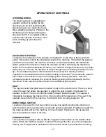
1. While seated on the machine, adjust the steering wheel to desired position using the tilt
lever.
2. Turn the
Key switch ON
(I). The Battery Gauge will light up and display the
Remaining
Battery Life.
3. Select one of the five available
Modes
on the
Control Console
for the required task.
Refer to the
Operation Modes section
of this manual for a complete description of the
functions.
4. Determine the direction you need to travel by selecting
forward
or
reverse
on the
Directional Switch.
Vary the pressure exerted on the accelerator pedal to propel the
machine at the desired speed.
5. Stepping on the
Accelerator Pedal
turns on the
Transport,
Brushes, Water Flow,
Vacuum
and lowers the
Rear Squeegee
accordingly to the Mode selected. If the
operator steps on the accelerator pedal before, or turns the key switch “ON” at the same
time, the machine will not move as a safety precaution. Simply remove your foot off the
pedal and step on the pedal again to drive the machine. Please refer to the
Main
Operation Modes section
of this manual for a complete description of the functions.
6. When
Reverse
is selected on the Directional Switch, the Rear Squeegee is
automatically raised when you step on the accelerator pedal. However, the scrub
brushes will continue to rotate and solution will continue to flow.
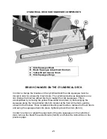
7. Start scrubbing by driving the machine forward in a straight line at ¾ speed and overlap
each pass by 2 to 3 inches. Adjust your speed, brush pressure, and solution flow
according to the condition of the floor.
CAUTION!
To avoid any damage to the floor, keep the machine moving when the brushes
are turned on.
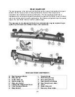
8. When scrubbing, check behind the machine occasionally to see that all the dirty water is
being picked up. If streaking occurs, your
Recovery Tank
may be
full
, the
Squeegee
hose
may be
clogged
, or the
Rear Squeegee
may require some
adjustment.
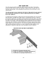
9. Make the necessary adjustments on the
Rear and Side Squeegees
if streaking occurs
both in straight paths and in turns. Pleas refer to the
Rear Squeegee
and
Side
Squeegee
section of this manual before making any adjustments.
10. In cases where the floors are extremely soiled and dirty, the
Double Scrub
mode may
be needed. As described in the
Operation Modes section
of this manual, this mode
allows the operator to be able to scrub an area without recovering the cleaning solution
with the rear squeegee in the raised position (no vacuum) to allow the cleaning solution
a longer time to loosen dirt. A final pass on the same area is made with the mode
switched over to either
Full Function
or
Vacuum Only
mode to recover the dirty water.
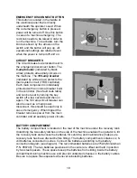
11. The recovery tank has a safeguard for overflow protection to guard against water from
entering the vacuum system when the recovery tank is full. The vacuum will stay ON for
15 seconds and then shut-off automatically. A ball float shut-off system has also been
integrated into the Recovery Tank. When the dirty water reaches a certain level, the ball
gets suctioned into the vacuum manifold and blocks the airflow thus, preventing the
machine from picking up more liquid. When this happens, the operator is then required
to stop scrubbing and empty the recovery tank.
Содержание SCV 28/32
Страница 1: ...SCV 28 32 RIDER SCRUBBER OPERATION SERVICE PARTS CARE ...
Страница 3: ...3 ...
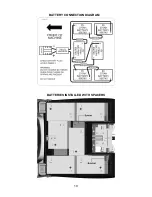
Страница 19: ...19 BATTERY CONNECTION DIAGRAM BATTERIES INSTALLED WITH SPACERS ...
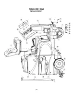
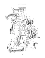
Страница 34: ...34 EXPLODED VIEWS MAIN ASSEMBLY I ...
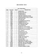
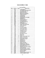
Страница 35: ...35 MAIN ASSEMBLY I BOM ...
Страница 36: ...36 MAIN ASSEMBLY II ...
Страница 37: ...37 MAIN ASSEMBLY II BOM ...
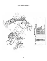
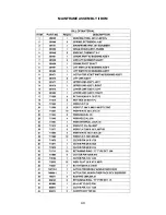
Страница 38: ...38 MAINFRAME ASSEMBLY I ...
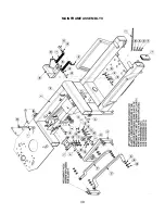
Страница 39: ...39 MAINFRAME ASSEMBLY II ...
Страница 40: ...40 MAINFRAME ASSEMBLY II BOM ...
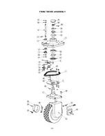
Страница 41: ...41 FRONT DRIVE ASSEMBLY ...
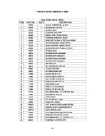
Страница 42: ...42 FRONT DRIVE ASSEMBLY BOM ...
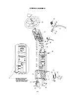
Страница 43: ...43 STEERING ASSEMBLY ...
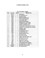
Страница 44: ...44 STEERING ASSEMBLY BOM ...
Страница 45: ...45 SOLUTION TANK ASSEMBLY SEAT ASSEMBLY ...
Страница 46: ...46 SOLUTION TANK ASSEMBLY SEAT ASSEMBLY BOM s ...
Страница 47: ...47 ELECTRICAL PANEL ...
Страница 48: ...48 CONSOLE ...
Страница 49: ...49 RECOVERY TANK I ...
Страница 50: ...50 RECOVERY TANK I BOM ...
Страница 51: ...51 RECOVERY TANK II ...
Страница 52: ...52 BATTERY BOX ASSEMBLY ...
Страница 53: ...53 PUMP ASSEMBLY ...
Страница 54: ...54 PUMP ASSEMBLY BOM ...
Страница 55: ...55 REAR AXLE ASSEMBLY ...
Страница 56: ...56 SQUEEGEE MECHANISM ASSEMBLY ...
Страница 57: ...57 28 REAR SQUEEGEE ASSEMBLY ...
Страница 58: ...58 28 REAR SQUEEGEE ASSEMBLY BOM ...
Страница 59: ...59 32 REAR SQUEEGEE ASSEMBLY ...
Страница 60: ...60 32 REAR SQUEEGEE ASSEMBLY BOM ...
Страница 61: ...61 28 CYLINDRICAL SCRUBDECK ITEMS 1 32 ...
Страница 62: ...62 28 CYLINDRICAL SCRUBDECK ITEMS 33 64 ...
Страница 63: ...63 28 CYLINDRICAL SCRUBDECK BOM ...
Страница 64: ...64 32 CYLINDRICAL SCRUBDECK ITEMS 1 32 ...
Страница 65: ...65 32 CYLINDRICAL SCRUBDECK ITEMS 33 64 ...
Страница 66: ...66 32 CYLINDRICAL SCRUBDECK BOM ...
Страница 67: ...67 28 DISK SCRUBDECK ...
Страница 68: ...68 28 DISK SCRUBDECK BOM ...
Страница 69: ...69 32 DISK SCRUBDECK ...
Страница 70: ...70 32 DISK SCRUBDECK BOM ...
Страница 71: ...71 CYLINDRICAL SCRUBDECK SIDE SQUEEGEE LEFT SIDE ...
Страница 72: ...72 CYLINDRICAL SCRUBDECK SIDE SQUEEGEE RIGHT SIDE ...
Страница 73: ...73 DISK SCRUBDECK SIDE SQUEEGEE LEFT SIDE ...
Страница 74: ...74 DISK SCRUBDECK SIDE SQUEEGEE RIGHT SIDE ...
Страница 75: ...75 CYLINDRICAL SCRUBDECK AND ROLLER BUMPER MOUNTING ...
Страница 76: ...76 SCV28CQP SCV32CQP BOM s ...
Страница 77: ...77 DISK SCRUBDECK AND ROLLER BUMPER MOUNTING ...
Страница 78: ...78 SCV28DQP SCV32DQP BOM s ...
Страница 79: ...79 PLUMBING DIAGRAM ...
Страница 80: ...80 WIRING DIAGRAMS TRIO CONNECTIONS ...
Страница 81: ...81 P3 TRIO CONNECTIONS ...
Страница 82: ...82 P2 TRIO CONNECTIONS ...
Страница 83: ...83 WIRE COLORS CODES ...